Download to read offline


![Dual Dimensioning – Bracket Method
• Millimeter value is enclosed in square
brackets. A note should be placed on the
drawing such as: DIMENSIONS IN [ ]
ARE MILLIMETERS.](https://image.slidesharecdn.com/dimensionandtolerancingppt-230203220244-a69a25ce/75/Dimension-and-Tolerancing-ppt-ppt-12-2048.jpg)
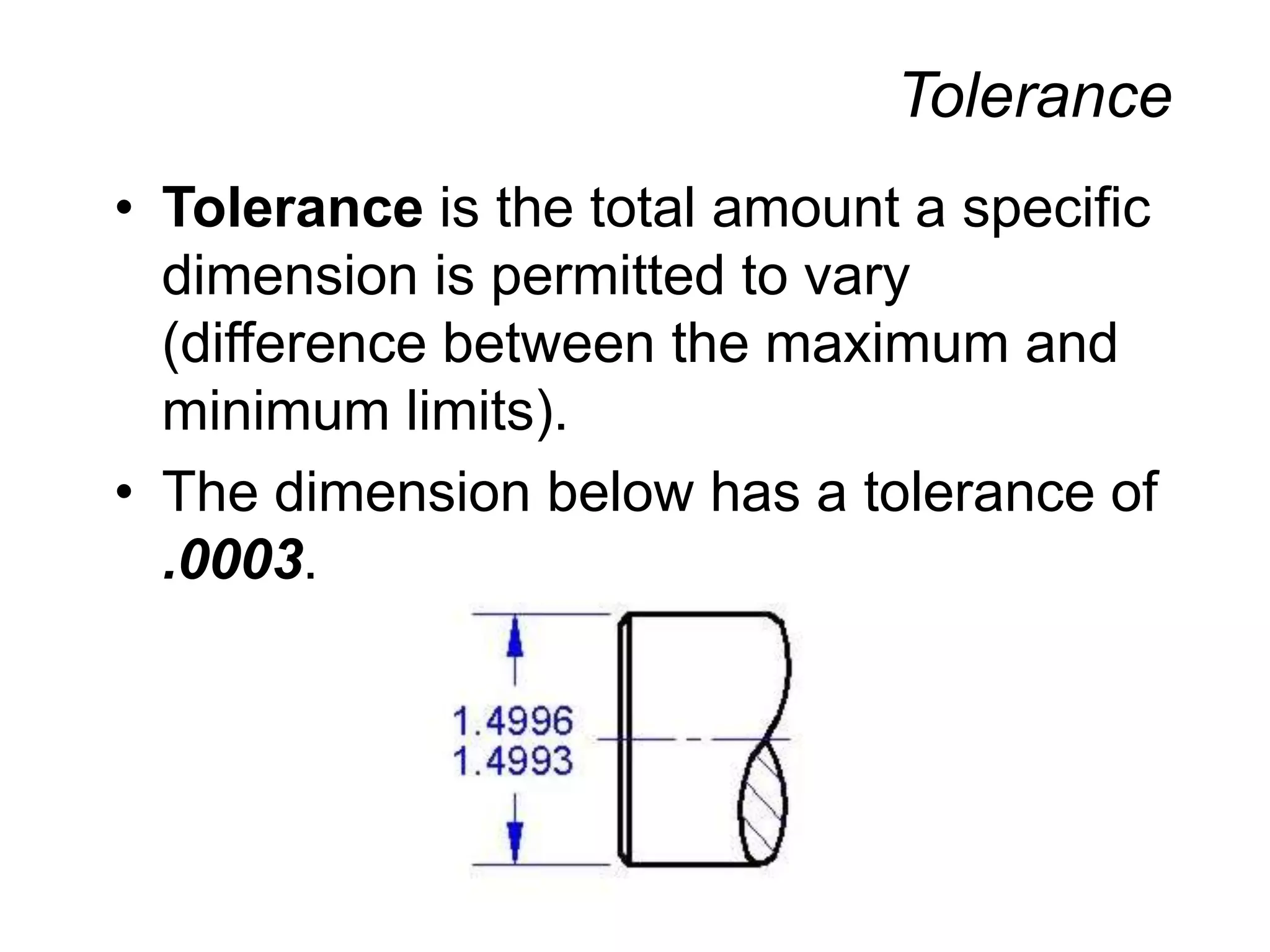


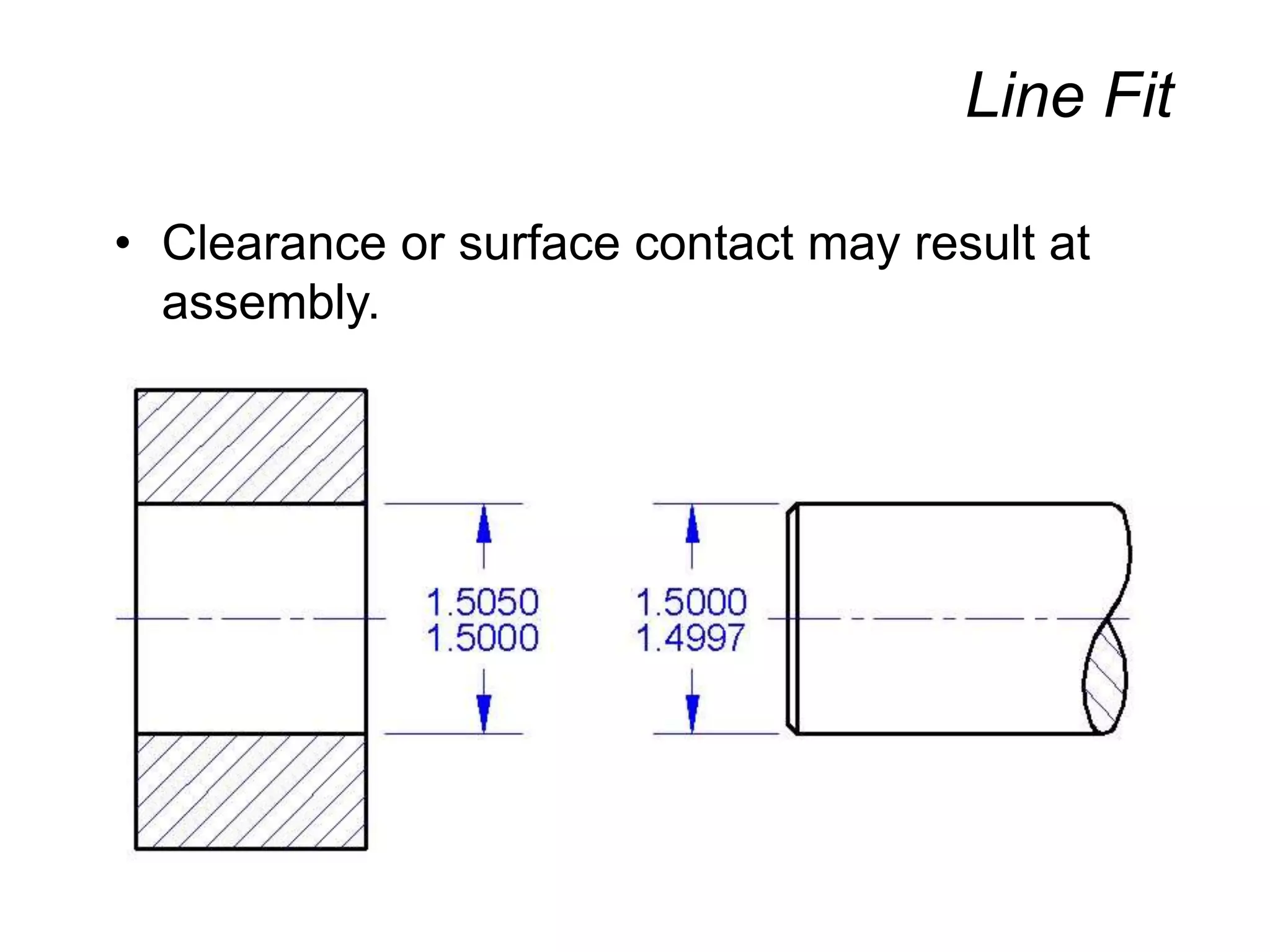
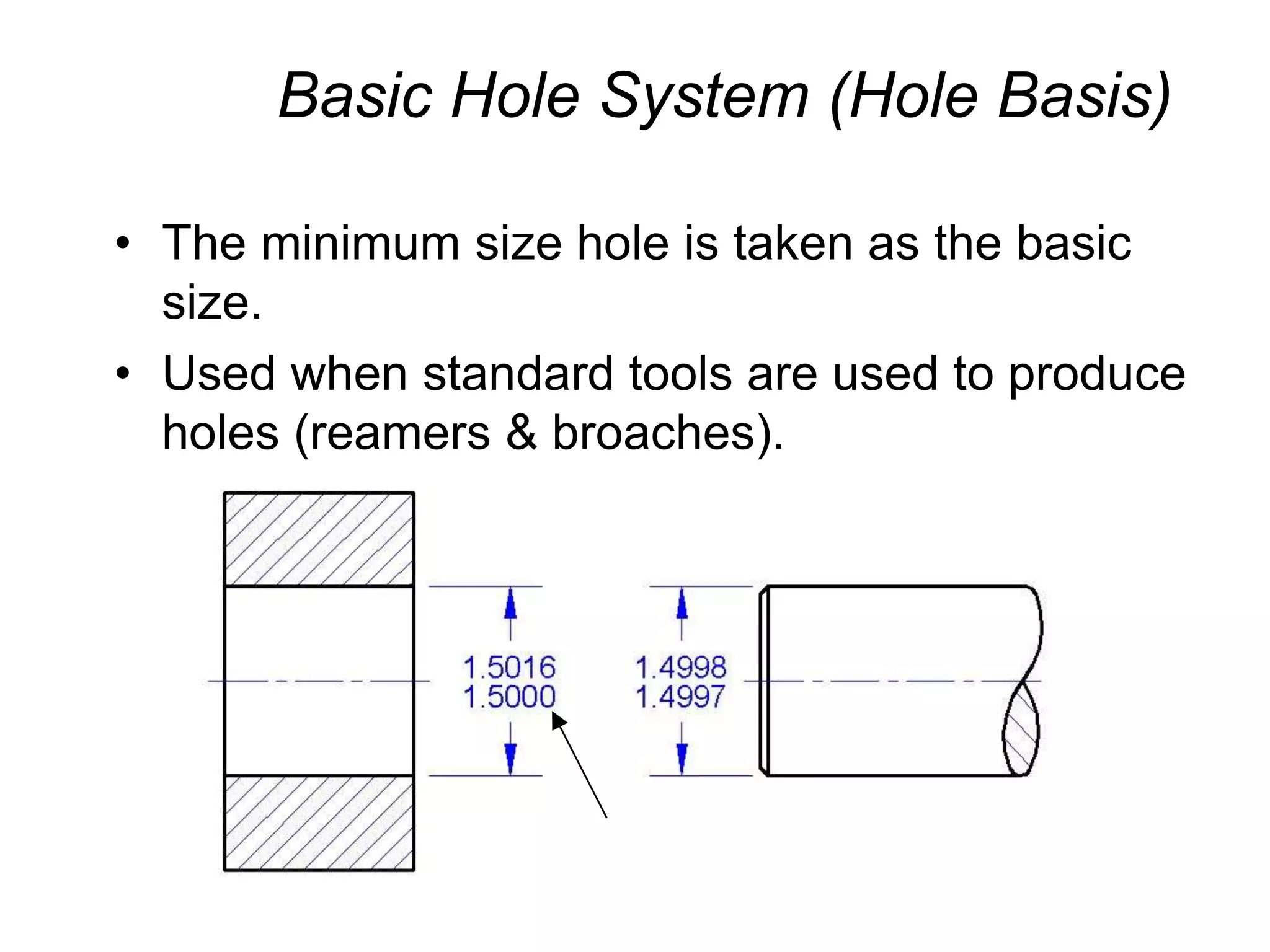


- The document discusses various methods for dimensioning and tolerancing parts in engineering drawings, including dimensioning different geometric shapes, coordinate dimensioning, tabular dimensioning, dual dimensioning, and specifying fits and tolerances. - It explains concepts like maximum material condition, allowance, nominal/basic/actual sizes, and types of fits including clearance, interference, transition, and line fits. - Tables are presented showing how to specify tolerances for holes and shafts based on fit class and size range in both inch and metric systems.


![Ppt Fits Tolerances[1]](https://cdn.slidesharecdn.com/ss_thumbnails/pptfitstolerances1-091107045206-phpapp01-thumbnail.jpg?width=640&height=640&fit=bounds)


