Downloaded 146 times


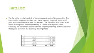
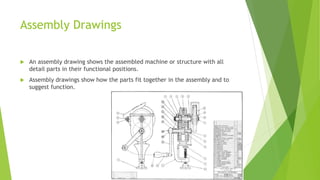


Production drawings provide the necessary information for manufacturing and assembling products. They include detail drawings of individual parts, assembly drawings showing how all parts fit together, and a bill of materials listing each part. Production drawings define the size, shape, and specifications of components as well as how they are produced and assembled through views, dimensions, tolerances, materials, and other annotations following standard conventions. Assembly drawings in particular show the assembled machine or structure with all parts in their functional positions to illustrate fitting and function.


