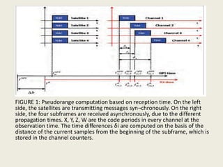
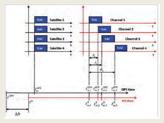
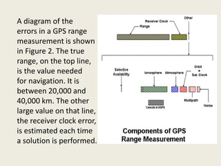
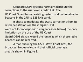
Downloaded 522 times


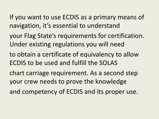
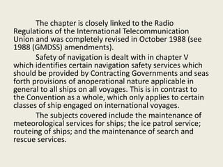
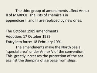
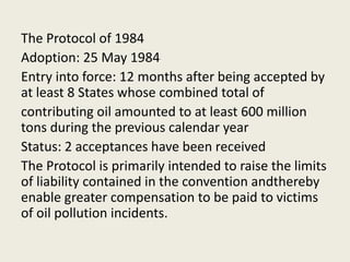
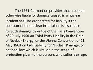
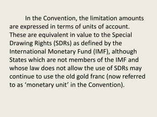
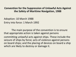
![• The improvement of GPS positioning doesn't require
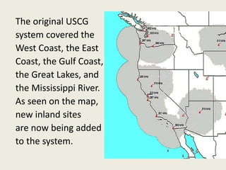
simultaneous measurements of two or more receivers in
any case, but can also be done by special use of a single
device.
• In the 1990s when even handheld receivers were quite
expensive, some methods of Quasi-Differential [QDGPS]
were developed, using the receiver by quick turns of
positions or loops of 3-10 survey points.
• QD - The analysis of errors computed using the Global
Positioning System is important for understanding how
GPS works, and for knowing what magnitude errors
should be expected. The Global Positioning System
makes corrections for receiver clock errors and other
effects but there are still residual errors which are not
corrected.](https://image.slidesharecdn.com/nav-5opruseecdis-150212205436-conversion-gate01/85/ECDIS-NAVIGATION-5-38-320.jpg)


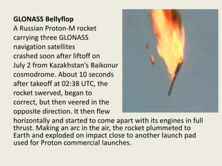
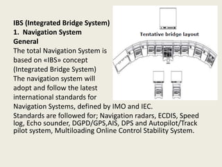
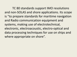
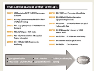
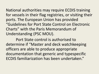
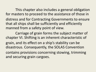
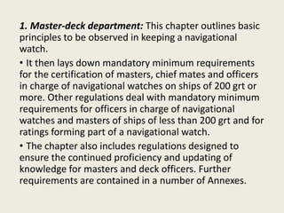
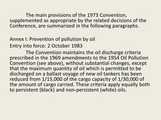
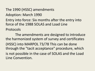
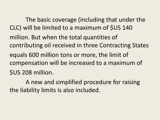
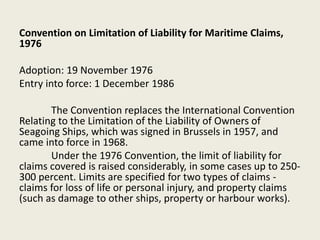
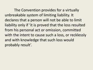
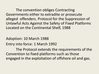
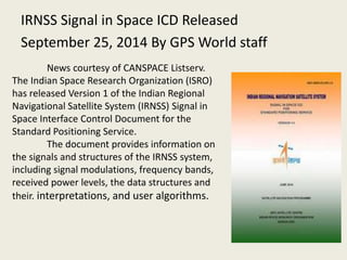
![The satellites would be launched 3 at a time on the
heavy-lift Proton rocket. Due to the large number of
satellites needed for the program, NPO PM
delegated the manufacturing of the satellites to PO
Polyot in Omsk, which had better production
capabilities.
Originally, GLONASS was designed to have an
accuracy of 65 m, but in reality it had an accuracy of
20 m in the civilian signal and 10 m in the military
signal.[6] The first generation GLONASS satellites
were 7.8 m tall, had a width of 7.2 m, measured
across their solar panels, and a mass of 1,260 kg.](https://image.slidesharecdn.com/nav-5opruseecdis-150212205436-conversion-gate01/85/ECDIS-NAVIGATION-5-132-320.jpg)
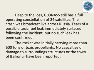
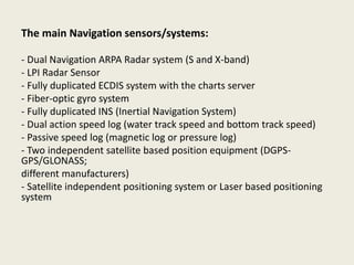
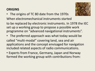
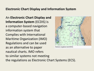
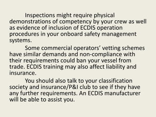
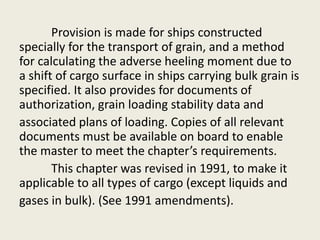
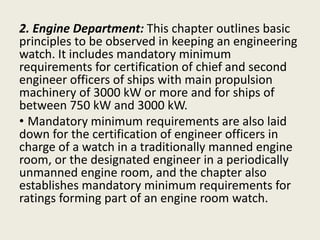
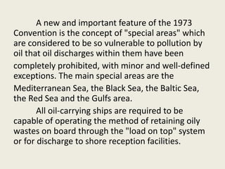
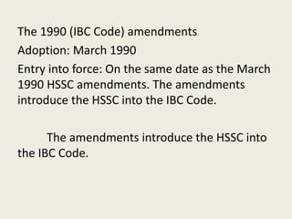
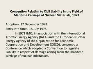
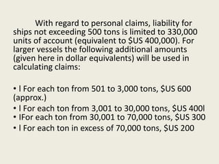
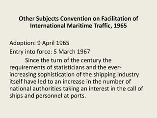
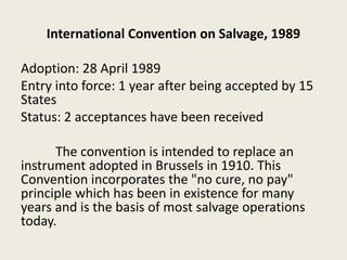
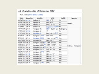
![The crashed Proton-M rocket employed a DM-03
booster, which was being used for the first time since
December 2010, when another Proton-M rocket with the
same booster failed to deliver another three GLONASS
satellites into orbit, crashing into the Pacific Ocean 1,500
kilometers from Honolulu.
A Russian government investigation revealed that at
least “three of six angular rate sensors [on the booster stage]
were installed incorrectly,” to be specific, upside-down.
Examination of the wreckage discovered traces of
forced, incorrect installation on three sensors. Assembly-line
testing at the factory failed to detect the faulty installation.](https://image.slidesharecdn.com/nav-5opruseecdis-150212205436-conversion-gate01/85/ECDIS-NAVIGATION-5-140-320.jpg)


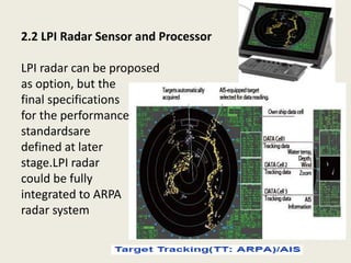


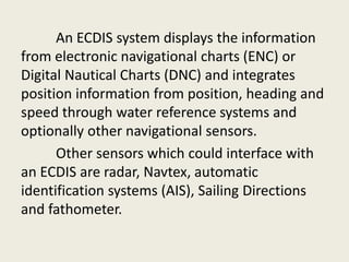
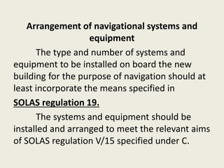
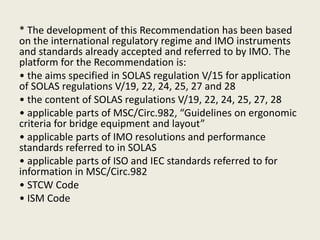
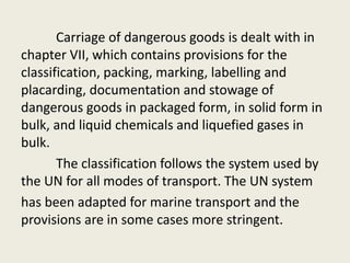
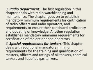
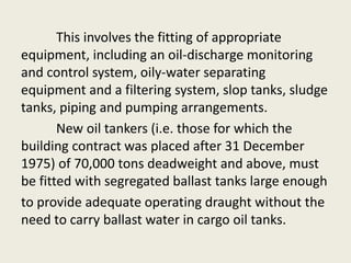
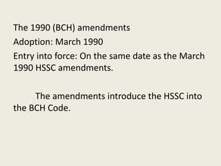
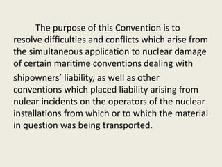
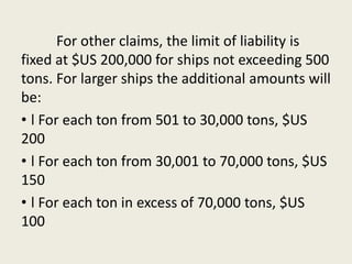
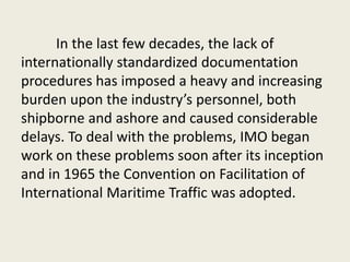
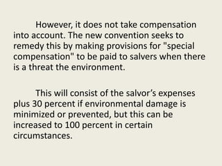
![REGULATIONS
ECDIS (as defined by IHO Publications S-52 and S-
57)[5] is an approved marine navigational chart and
information system, which is accepted as complying with
the conventional paper charts required by Regulation
V/19 of the 1974 IMO SOLAS Convention.[6] as amended.
The performance requirements for ECDIS are
defined by IMO and the consequent test standards have
been developed by the International Electrotechnical
Commission (IEC) in International Standard IEC 61174.[7]
The future standard for ENCs will be defined in IHO
Publication S-100.](https://image.slidesharecdn.com/nav-5opruseecdis-150212205436-conversion-gate01/85/ECDIS-NAVIGATION-5-268-320.jpg)


This document provides an overview of differential GPS (DGPS) and its history. It explains that DGPS uses fixed, ground-based reference stations to broadcast corrections to improve GPS accuracy from 15 meters to about 10 cm. Selective availability was introduced by the US military to degrade civilian GPS but was turned off in 2000. DGPS was developed as a solution, broadcasting corrections to offset errors and allow 5 meter accuracy, meeting most civilian needs. It has expanded to cover many waterways through systems like the US Coast Guard's National DGPS.


