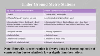
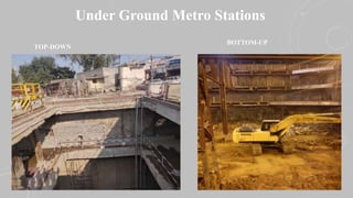
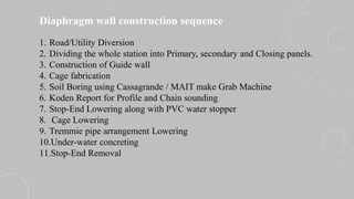
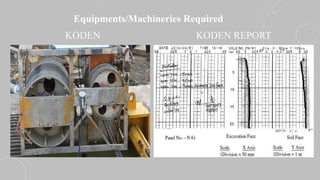
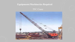
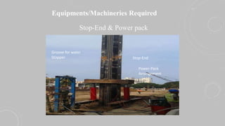
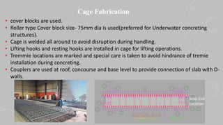
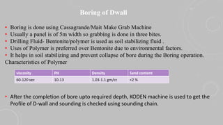
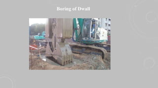
CONSTRUCTION OF DIAPHRAGM WALL
ANURAG
AM/QUALITY
EMP ID- 4078
Under Ground Metro Stations
Top Down Method of Construction Bottom Up Method of Construction
1. D-wall 1. Soldier Piles/ Secant piles
2. Plunge/Temporary columns are used 2. waler/struts arrangements are used
3. Construction Pattern- Guide wall-> Dwall-
>Plunge/Temporary columns->Roof slab->
Concourse slab->Base slab-> Columns
3. Construction Pattern- Soldier/Secant piles->Base slab->
Columns/Walls->Concourse slab->column walls-> roof slab
3. Couplers are used 3. Lapping is preferred
4. Relatively Fast 4. Relatively slow
5. Preferred at Soil Strata 5. Preferred at Rocky Strata
6. Wall finish is Relatively bad 6. Finish is relatively good
Note- Entry/Exits construction is always done by bottom up mode of
construction due to relatively lower depth than the stations.
Under Ground Metro Stations
TOP-DOWN
BOTTOM-UP
Diaphragm wall construction sequence
1. Road/Utility Diversion
2. Dividing the whole station into Primary, secondary and Closing panels.
3. Construction of Guide wall
4. Cage fabrication
5. Soil Boring using Cassagrande / MAIT make Grab Machine
6. Koden Report for Profile and Chain sounding
7. Stop-End Lowering along with PVC water stopper
8. Cage Lowering
9. Tremmie pipe arrangement Lowering
10.Under-water concreting
11.Stop-End Removal
Equipments/Machineries Required
Grab Machine
Equipments/Machineries Required
KODEN KODEN REPORT
Equipments/Machineries Required
TFC Crane
Equipments/Machineries Required
Stop-End & Power pack
Power-Pack
Arrangement
Stop-End
Groove for water
Stopper
Road/Utility Diversion
• Utility Identification (Charted/Uncharted)
• Cross trenching all along the alignment
• Diversion
Primary/Secondary and Closing Panels
• Station layout is divided into primary , secondary and closing panels
based on the construction sequence.
• Primary panels- both side stopend.
• Secondary panels- single side stopend
• Closing panel- no stopend
Guide wall
• Guide wall is L-shaped RCC structure usually 1.5m deep and it act as a casing to the D-
wall.
• Act as working platform for concreting and Cage Lowering as well as for restricting the
movement of Cage during concreting
• 50mm wider than the required width of D-wall
• Grade of Concrete- M-25
• Reinforcement used- 8mm, 10mm dia.
Cross sectional layout
Cage Fabrication
• cover blocks are used.
• Roller type Cover block size- 75mm dia is used(preferred for Underwater concreting
structures).
• Cage is welded all around to avoid disruption during handling.
• Lifting hooks and resting hooks are installed in cage for lifting operations.
• Tremmie locations are marked and special care is taken to avoid hindrance of tremie
installation during concreting.
• Couplers are used at roof, concourse and base level to provide connection of slab with D-
walls.
Stop-End
Location
Boring of Dwall
• Boring is done using Cassagrande/Mait Make Grab Machine
• Usually a panel is of 5m width so grabbing is done in three bites.
• Drilling Fluid- Bentonite/polymer is used as soil stabilizing fluid .
• Uses of Polymer is preferred over Bentonite due to environmental factors.
• It helps in soil stabilizing and prevent collapse of bore during the Boring operation.
Characteristics of Polymer
• After the completion of bore upto required depth, KODEN machine is used to get the
Profile of D-wall and sounding is checked using sounding chain.
viscosity PH Density Sand content
60-120 sec 10-13 1.03-1.1 gm/cc <2 %
Boring of Dwall
Stop-End/Cage Lowering
• Prior to stopend lowering it is equipped with PVC-Water stopper for sealing
joints of two adjacent D-walls.
• After completion of bore Stopend is lowered using Crane and it is supported
using concrete blocks.
• The excavated area on the back side of stopend is filled using gunny bags
filled with soil in order to restrict the movement of Stop-end during
concreting of D-wall.
• Now Fabricated cage is being lowered into the bore using Crane
arrangements.
• After lowering of cage its position on top is locked using welding with guide
wall reinforcement.
• It is done in order to restrict the cage uplift during concreting.
Stop-End/Cage Lowering
Concreting
• 2 nos Tremie Hopper arrangement of 200/250mm Tremie pipe is used for bore width
of 5000mm as flow of concrete is expected to be 1500mm on both side of the tremie.
• Arrangements of assembly should be such that it is 150-200mm above the bore
bottom.
• Polymer density to be checked prior to concreting and it is to be maintained as per
requirement.
• Polymer retrieval arrangements shall be made for retrieval of polymer during
concreting.
• Concreting is started and continued at same pace from both the arrangements.
• Concreting is continued till the concrete has reached the final Cutoff level.
• Tremmie should be removed at regular interval after soundness checking.
• It should always be ensured that tremie is at least 2m inside concrete during removal.
Grade of Concrete Slump Temperature Aggregate size
M-40 150-200 5-32 C 20 mm down
Stop-End Removal
STOPEND
Hopper
Tremmie Pipe
Concrete Block
Concreting Through Transit
Mixers
Stop-End Removal
• Stopend is made loose using powerpack arrangements
• After that it is removed slowly using Crane.
• It should be ensured that PVC water stopper should not come out along with stopend.
• In that case proper measures should be taken during Excavation Process
Sample Video
Questions ????

D wall construction

  • 1.
    CONSTRUCTION OF DIAPHRAGMWALL ANURAG AM/QUALITY EMP ID- 4078
  • 2.
    Under Ground MetroStations Top Down Method of Construction Bottom Up Method of Construction 1. D-wall 1. Soldier Piles/ Secant piles 2. Plunge/Temporary columns are used 2. waler/struts arrangements are used 3. Construction Pattern- Guide wall-> Dwall- >Plunge/Temporary columns->Roof slab-> Concourse slab->Base slab-> Columns 3. Construction Pattern- Soldier/Secant piles->Base slab-> Columns/Walls->Concourse slab->column walls-> roof slab 3. Couplers are used 3. Lapping is preferred 4. Relatively Fast 4. Relatively slow 5. Preferred at Soil Strata 5. Preferred at Rocky Strata 6. Wall finish is Relatively bad 6. Finish is relatively good Note- Entry/Exits construction is always done by bottom up mode of construction due to relatively lower depth than the stations.
  • 3.
    Under Ground MetroStations TOP-DOWN BOTTOM-UP
  • 4.
    Diaphragm wall constructionsequence 1. Road/Utility Diversion 2. Dividing the whole station into Primary, secondary and Closing panels. 3. Construction of Guide wall 4. Cage fabrication 5. Soil Boring using Cassagrande / MAIT make Grab Machine 6. Koden Report for Profile and Chain sounding 7. Stop-End Lowering along with PVC water stopper 8. Cage Lowering 9. Tremmie pipe arrangement Lowering 10.Under-water concreting 11.Stop-End Removal
  • 5.
  • 6.
  • 7.
  • 8.
    Equipments/Machineries Required Stop-End &Power pack Power-Pack Arrangement Stop-End Groove for water Stopper
  • 9.
    Road/Utility Diversion • UtilityIdentification (Charted/Uncharted) • Cross trenching all along the alignment • Diversion
  • 10.
    Primary/Secondary and ClosingPanels • Station layout is divided into primary , secondary and closing panels based on the construction sequence. • Primary panels- both side stopend. • Secondary panels- single side stopend • Closing panel- no stopend
  • 11.
    Guide wall • Guidewall is L-shaped RCC structure usually 1.5m deep and it act as a casing to the D- wall. • Act as working platform for concreting and Cage Lowering as well as for restricting the movement of Cage during concreting • 50mm wider than the required width of D-wall • Grade of Concrete- M-25 • Reinforcement used- 8mm, 10mm dia. Cross sectional layout
  • 12.
    Cage Fabrication • coverblocks are used. • Roller type Cover block size- 75mm dia is used(preferred for Underwater concreting structures). • Cage is welded all around to avoid disruption during handling. • Lifting hooks and resting hooks are installed in cage for lifting operations. • Tremmie locations are marked and special care is taken to avoid hindrance of tremie installation during concreting. • Couplers are used at roof, concourse and base level to provide connection of slab with D- walls. Stop-End Location
  • 13.
    Boring of Dwall •Boring is done using Cassagrande/Mait Make Grab Machine • Usually a panel is of 5m width so grabbing is done in three bites. • Drilling Fluid- Bentonite/polymer is used as soil stabilizing fluid . • Uses of Polymer is preferred over Bentonite due to environmental factors. • It helps in soil stabilizing and prevent collapse of bore during the Boring operation. Characteristics of Polymer • After the completion of bore upto required depth, KODEN machine is used to get the Profile of D-wall and sounding is checked using sounding chain. viscosity PH Density Sand content 60-120 sec 10-13 1.03-1.1 gm/cc <2 %
  • 14.
  • 15.
    Stop-End/Cage Lowering • Priorto stopend lowering it is equipped with PVC-Water stopper for sealing joints of two adjacent D-walls. • After completion of bore Stopend is lowered using Crane and it is supported using concrete blocks. • The excavated area on the back side of stopend is filled using gunny bags filled with soil in order to restrict the movement of Stop-end during concreting of D-wall. • Now Fabricated cage is being lowered into the bore using Crane arrangements. • After lowering of cage its position on top is locked using welding with guide wall reinforcement. • It is done in order to restrict the cage uplift during concreting.
  • 16.
  • 17.
    Concreting • 2 nosTremie Hopper arrangement of 200/250mm Tremie pipe is used for bore width of 5000mm as flow of concrete is expected to be 1500mm on both side of the tremie. • Arrangements of assembly should be such that it is 150-200mm above the bore bottom. • Polymer density to be checked prior to concreting and it is to be maintained as per requirement. • Polymer retrieval arrangements shall be made for retrieval of polymer during concreting. • Concreting is started and continued at same pace from both the arrangements. • Concreting is continued till the concrete has reached the final Cutoff level. • Tremmie should be removed at regular interval after soundness checking. • It should always be ensured that tremie is at least 2m inside concrete during removal. Grade of Concrete Slump Temperature Aggregate size M-40 150-200 5-32 C 20 mm down
  • 18.
    Stop-End Removal STOPEND Hopper Tremmie Pipe ConcreteBlock Concreting Through Transit Mixers
  • 19.
    Stop-End Removal • Stopendis made loose using powerpack arrangements • After that it is removed slowly using Crane. • It should be ensured that PVC water stopper should not come out along with stopend. • In that case proper measures should be taken during Excavation Process
  • 20.
  • 21.