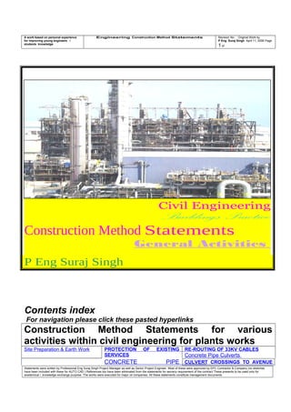
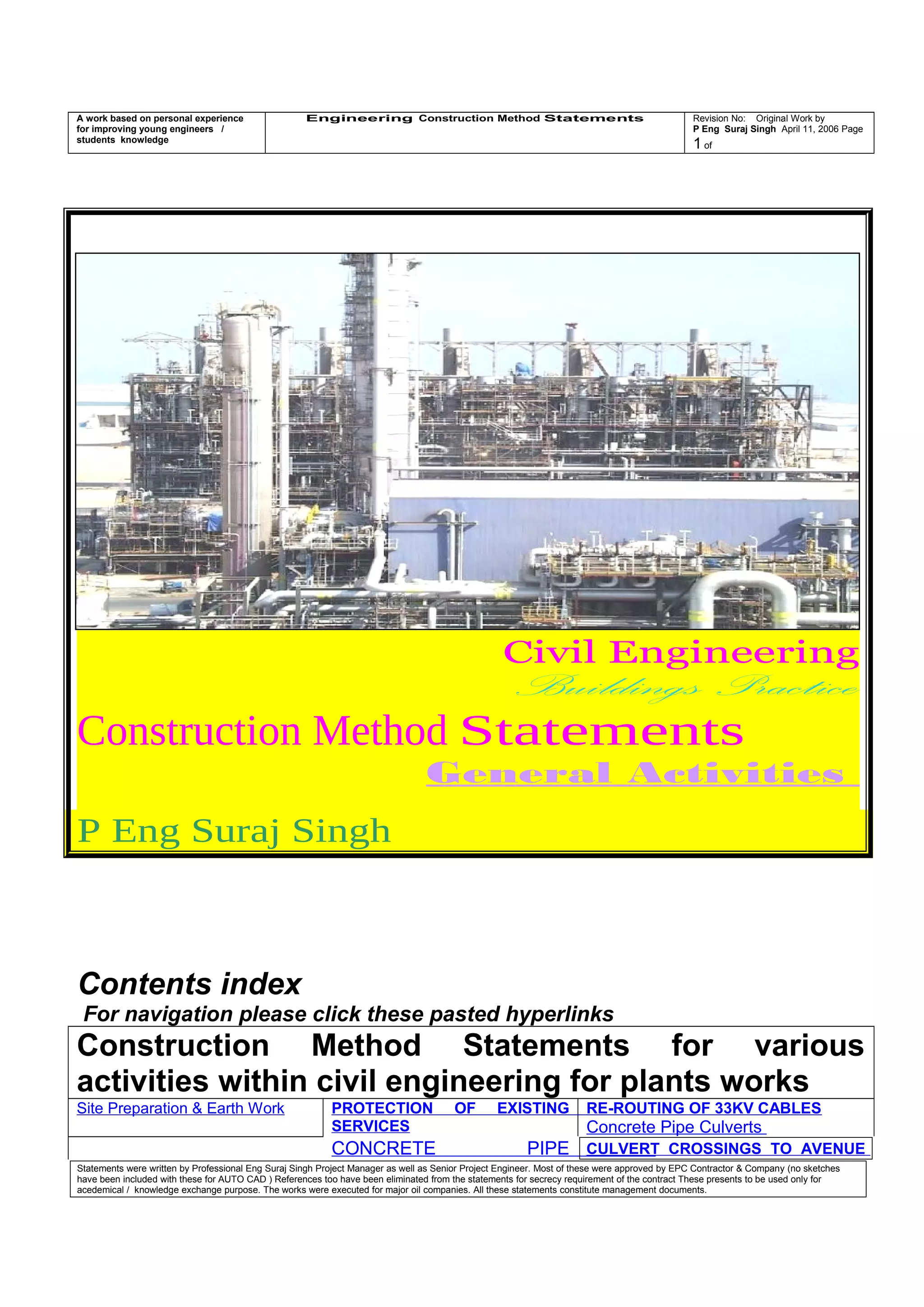
SlideShare a Scribd company logo
1 of 499
A work based on personal experience
for improving young engineers /
students knowledge
Engineering Construction Method Statements Revision No: Original Work by
P Eng Suraj Singh April 11, 2006 Page
1 of
Civil Engineering
Buildings Practice
Construction Method Statements
General Activities
P Eng Suraj Singh
Contents index
For navigation please click these pasted hyperlinks
Construction Method Statements for various
activities within civil engineering for plants works
Site Preparation & Earth Work PROTECTION OF EXISTING
SERVICES
RE-ROUTING OF 33KV CABLES
Concrete Pipe Culverts
CONCRETE PIPE CULVERT CROSSINGS TO AVENUE
Statements were written by Professional Eng Suraj Singh Project Manager as well as Senior Project Engineer. Most of these were approved by EPC Contractor & Company (no sketches
have been included with these for AUTO CAD ) References too have been eliminated from the statements for secrecy requirement of the contract These presents to be used only for
acedemical / knowledge exchange purpose. The works were executed for major oil companies. All these statements constitute management documents.
A work based on personal experience
for improving young engineers /
students knowledge
Engineering Construction Method Statements Revision No: Original Work by
P Eng Suraj Singh April 11, 2006 Page
2 of
CONCRETING TO WALLS OF
CENTRAL CONTROL BUILDING /
LABORATORY
CULVERTS E AND MAIN HIGHWAY.
PLACING CONCRETE ON
SERVICE
WATER TANK 58-TK-205
FOUNDATIONS
CONCRETE REPAIR
Top
CONSTRUCTION OF PIPE
RACK BASES
EXCAVATION IN Operating
Authority CONTROLLED AREAS
CONSTRUCTION OF MAIN
SUBSTATION
REMOVAL OF HAZARDOUS
MATERIALS
CONSTRUCTION OF FLOOR SLAB
CENTRAL CONTROL BUILDING
MORTAR FOR BLOCKWORK CONTROL OF CAMP SEWAGE SYSTEM
STRUCTURAL STEEL-PIPERACKS COMPRESSORS’ STRUCTURES
RCC COLUMN PLATE INSERTS
EXCAVATION FOR
132KV CABLE INTERCONNECTION
ROAD CROSSING FOR 132
KV ROUTE
NIGHT SHIFT WORKING -
EARTHWORKS
GROUTING TO PIPE RACK FOUNDATION
BASES
CEMENTITIOUS GROUTING TO
FOUNDATION BASES
ETYLENE COMPRESSOR
MASSIVE FOUNDATION (CONCRETE
POUR
PROPANE COMPRESSOR
MASSIVE FOUNDATION (CONCRETE POUR)
PROPANE COMPRESSOR
MASSIVE FOUNDATION (CONCRETE
POUR)
PROPANE COMPRESSOR
MASSIVE FOUNDATION (CONCRETE
POUR
PROPANE COMPRESSOR
MASSIVE FOUNDATION (CONCRETE POUR
PROPANE COMPRESSOR
MASSIVE FOUNDATION (CONCRETE
POUR
SEAWATER BASIN
(WATER TIGHTNESS BS 8007 : 1987 )
SEAWATER BASIN
(WATER TIGHTNESS BS 8007 : 1987 )
SEAWATER BASIN
(WATER TIGHTNESS BS 8007 : 1987 )
ADMINISTRATION BUILDING
STAIR LANDING EXTENSION AT GRID 4
J
ADMINISTRATION BUILDING
STAIR LANDING EXTENSION AT GRID 4 J
ADMINISTRATION BUILDING
STAIR LANDING EXTENSION AT GRID 4
J
FENCING
Top
ADMINISTRATION BUILDING
CERAPlant Operating Authority TILES
FLOORING SYSTEM
ADMINISTRATION BUILDING
CERAPlant Operating Authority TILES
FLOORING SYSTEM
ADMINISTRATION BUILDING
PLASTERING AND RENDERING
ADMINISTRATION BUILDING
ROOFING SYSTEM
ROOFING SYSTEM BUILDINGS
ROOFING SYSTEM
CRACKED GAS COMPRESSOR TABLE TOP
CONCRETE POUR
WATER TIGHTNESS TESTS FOR THE
COLLECTION SUMPS ACCORDING TO
BS 8007 : 1987 SECTION 9
WATER TIGHTNESS TESTS FOR THE
COLLECTION SUMPS ACCORDING TO
BS 8007 : 1987 SECTION 9
ADMINISTRATION BUILDING
MARBLE FLOORING
ETHYLENE GAS COMPRESSOR
TABLE TOP POUR
PROPANE GAS COMPRESSOR
TABLE TOP POUR
EXPANSION JOINTS IN DITCHES
Top
CONCRETE COATING
USING MASTER SEAL 550
DEWATERING FOR THE 84” GRE PAIR
LINE PARALLEL TO
CORNICHE ROAD EAST WEST
Statements were written by Professional Eng Suraj Singh Project Manager as well as Senior Project Engineer. Most of these were approved by EPC Contractor & Company (no sketches
have been included with these for AUTO CAD ) References too have been eliminated from the statements for secrecy requirement of the contract These presents to be used only for
acedemical / knowledge exchange purpose. The works were executed for major oil companies. All these statements constitute management documents.
A work based on personal experience
for improving young engineers /
students knowledge
Engineering Construction Method Statements Revision No: Original Work by
P Eng Suraj Singh April 11, 2006 Page
3 of
CERAPlant Operating Authority WALL
TILES FIXING
BEDDING AND GRAVEL FILLING
BENEATH 60 “ DIA PIPE COOLING
WATER PIPE
EXTERNAL CONCRETE PROTECTION
ADMINISTRATION BUILDING
ABOVE GROUND CONCRETE
PROTECTION
USING MASTERSEAL 300 H
ABOVE GROUND CONCRETE
PROTECTION
USING MASTERSEAL 300 H
HAND EXCAVATION TO INSTALL
TELEPHONE DUCTS BETWEEN BOX NO. 20
TO TELECOM CENTRE
BACKFILLING OF THE WEST SIDE OF
THE QUENCH TOWER FOUNDATION –
(RIB)
EXCAVATION -
COOLING WATER OUTFALL CHAMBER
DRILLING OF HOLES ON
PIPE RACK & STRUCTURES ON SITE
SITE OFFICE ESTABLISHMENT Welding of Earthing Lugs on
East West Piperack (SR0099A &B)
FILLING AROUND ALL THE PIPES WITHIN THE
Plant AREA
PRECASTING MAN HOLES
CATCH BASIN AND
VALVE CHAMBERS
TERMINATION DETAIL TO
PROTECTIVE MEMBRANE AROUND
RCC COLUMNS SUPPORTING THE
STRUCTURAL STEEL
COLUMNS FOR PIPE RACKS
CASE (1) WITH ALUMINIUM BEAD
CASE (2) WITH REBATE
CASE (3) GRAVEL FILL
CASE (4) PAVING
TERMINATION DETAIL TO PROTECTIVE
MEMBRANE AROUND RCC COLUMNS
SUPPORTING THE STRUCTURAL STEEL
COLUMNS FOR PIPE RACKS
CASE (1) WITH ALUMINIUM BEAD
CASE (2) WITH REBATE
CASE (3) GRAVEL FILL
CASE (4) PAVING
Top ROAD CROSSING FOR LAYING 2 PIPES
1 FOR 20” RAW ETHANE & 1 FOR 6”
PROPANE
FIRST STREET Operating Authority
ENTRY
ROAD CROSSING FOR LAYING 2 PIPES
1 FOR 20” RAW ETHANE
&
1 FOR 6” PROPANE
FIRST STREET Operating Authority ENTRY
DIRECTIONAL BORING
FOR LAYING SLEEVES FOR
2 PIPES
1 # 20” RAW ETHANE
&
1 # 6” PROPANE
Operating Authority Plant REFINERY
ENTRY
2 #s ROAD CROSSINGS
FOR LAYING
1 FOR 14” DESALINATED WATER
1 FOR 8”POTABLE WATER
&
1 FOR 20” RAW ETHANE
1 FOR 8” NATURAL GAS
1 FOR 6” PROPANE
AVENUE ‘C’
AT FIRE STATION
2 #s ROAD CROSSINGS
FOR LAYING
1 FOR 14” DESALINATED WATER
1 FOR 8”POTABLE WATER
&
1 FOR 20” RAW ETHANE
1 FOR 8” NATURAL GAS
1 FOR 6” PROPANE
AVENUE ‘C’
AT FIRE STATION
ADMINISTRATION BUILDING
GRC
PANEL FIXING
PAINTING ADMINISTRATION BUILDING PAINTING ADMINISTRATION BUILDING
Top
Statements were written by Professional Eng Suraj Singh Project Manager as well as Senior Project Engineer. Most of these were approved by EPC Contractor & Company (no sketches
have been included with these for AUTO CAD ) References too have been eliminated from the statements for secrecy requirement of the contract These presents to be used only for
acedemical / knowledge exchange purpose. The works were executed for major oil companies. All these statements constitute management documents.
A work based on personal experience
for improving young engineers /
students knowledge
Engineering Construction Method Statements Revision No: Original Work by
P Eng Suraj Singh April 11, 2006 Page
4 of
ROAD CROSSING FOR LAYING 2 PIPES
1 FOR 20” RAW ETHANE
&
1 FOR 6”PROPANE
AVENUE ‘C’
EARTHWORKS SURVEY
SYSTEM
ROAD CROSSING FOR LAYING
84”G R E PAIR SEAWATER
COOLING LINES
AT
AVENUE ‘D’ / CORNICHE
JUNCTION
ROAD CROSSING FOR LAYING
84”G R E PAIR SEAWATER
COOLING LINES
AT
AVENUE ‘D’ / CORNICHE
JUNCTION
TENNIS COURTS SURFACING
Top
PRECASTING LIGHTING POLES
FOUNDATIONS
LIGHTING POLES
FOUNDATIONS
SEA WATER SURGE BASIN
CONCRETE PROTECTION
MASTER SEAL 550
CONCRETE COATING OF STRUCTURES
USING MASTERSEAL 550
ABOVE GROUND CONCRETE
PROTECTION
SEAWATER SURGE BASIN
SEA WATER SURGE BASIN JOINT
SEAL
PAINTING
SUB STATIONS
PAINTING
SUB STATIONS
ELECTRICAL & INSTRUMENTATION
TRENCHES
ELECTRICAL & INSTRUMENTATION
TRENCHES
PULL PITS
ROAD CROSSING TO MAKE GOOD
WEARING COURSE OVER COMPLETED
1# FOR 14” DESALINATED WATER
&
1# FOR 8”POTABLE WATER
AVENUE ‘C’
PULL PITS
ROAD CROSSING TO MAKE GOOD
WEARING COURSE OVER COMPLETED
132 KV ELECTRIC CABLE
AVENUE ‘C’
PULL PITS
ROAD CROSSING
TO MAKE GOOD (temporarily)
WEARING COURSE OVER COMPLETED
132 KV ELECTRIC CABLE
AVENUE ‘C’
DRINKING WATER
CONNECTION
Top
PROTECTION TO TRANSFORMER
FOUNDATION SIDES IN SUB STATIONS
WITH ALUMINIUM BEAD
TERMINATION FOR BELOW GROUND
AND MASTERSEAL 300H FOR ABOVE
GROUND IN GRAVEL FILL AREA
TIMBER DOORS FIXING
ADMINISTRATION BUILDING
GROUTING TO STEEL TANKS
BEARINGS ON RING BEAMS
GROUTING TO STEEL TANKS
BEARINGS ON RING BEAMS
EXCAVATION FOR CCB UNDERGROUND
WATER TANK
EXCAVATION FOR CCB
UNDERGROUND WATER TANK
SOAKAWAY CHAMBERS EPOXY FLOORING
BUILDINGS
EPOXY FLOORING
BUILDINGS
EPOXY FLOORING
BUILDINGS
VINYL WALL COVERING
BUILDINGS
DRY WALL LININGS
BUILDINGS
RUBBER FLOORING
(BUILDINGS)
RUBBER FLOORING
(BUILDINGS)
RUBBER FLOORING
(BUILDINGS)
RUBBER FLOORING
(BUILDINGS)
RUBBER FLOORING
(BUILDINGS)
Statements were written by Professional Eng Suraj Singh Project Manager as well as Senior Project Engineer. Most of these were approved by EPC Contractor & Company (no sketches
have been included with these for AUTO CAD ) References too have been eliminated from the statements for secrecy requirement of the contract These presents to be used only for
acedemical / knowledge exchange purpose. The works were executed for major oil companies. All these statements constitute management documents.
A work based on personal experience
for improving young engineers /
students knowledge
Engineering Construction Method Statements Revision No: Original Work by
P Eng Suraj Singh April 11, 2006 Page
5 of
SUSPENDED CEILINGS
ALL BUILDINGS
PIT 21 WATER CONNECTION
Top
CEMENT BASED NON SHRINK GROUTING TO
FOUNDATION BASES
USING MASTERFLOW 928 T
REPAIR OF CONCRETE FLOOR
SCREEDS
Top
REPAIR OF CONCRETE FLOOR
SCREEDS
EPOXY GROUTING TO
VIBRATING INSTALLATION BASES
USING MASTERFLOW 648 CP
GENERAL FOUNDATIONS
KERBS & INTERLOCKING BLOCKS
PAVING AROUND BUILDINGS
ERECTION OF STEEL STRUCTURES
(FOR HIGHER LEVELS)
VINYL FLOORING
BUILDINGS
CONCRETE PAVING CENTRAL CONTROL BUILDING
CERAPlant Operating Authority TILES
FLOORING SYSTEM
CONCRETE PLACEMENT
PRECAST RCC COVERS
CABLE & INSTRUMENTATION
TRENCHES
BLACK TOP REPAIR
IST STREET BETWEEN
AVENUE C & B
REPAIR OF
SINGLE LEAF SWING GATES
REPAIR TO
FLOOR SCREED LEVELS
RESIN INJECTION TO LEAKING JOINT
SEA WATER SURGE BASIN
RESIN INJECTION TO LEAKING JOINT
SEA WATER SURGE BASIN
RESIN INJECTION TO LEAKING JOINT
SEA WATER SURGE BASIN
FIRE WATER LINE EXCAVATION
AROUND CONSUMER RECEIPT
STATION
ROAD CROSSING
FOR LAYING
1 FOR 20” RAW ETHANE
1 FOR 6” PROPANE
FIRST STREET
ROAD CROSSING
FOR LAYING
1 FOR 20” RAW ETHANE
1 FOR 6” PROPANE
FIRST STREET
2 #s ROAD CROSSINGS
FOR LAYING
1 FOR 20” RAW ETHANE
1 FOR 8” NATURAL GAS
1 FOR 6” PROPANE
&
1 FOR 14”DESALINATED WATER
1FOR 8” POTABLE WATER
AVENUE -D
TREATMENT TO MOVED EXPANSION JOINTS
SEA WATER SURGE BASIN
Top
TESTING OF FRESH CONCRETE ON
SITE
Top
ROAD CROSSING
TO INSTALL CULVERT FOR
1# 14” DESALINATED WATER
CORNICHE ROAD / ROAD C
AT GUP GATE NOTH
ROAD CROSSING
TO INSTALL CULVERT
FOR
1 # 14” DESALINATED WATER
AVENUE ‘C’ ROAD GUP GATE EAST
MAIN ENTRANCE
Statements were written by Professional Eng Suraj Singh Project Manager as well as Senior Project Engineer. Most of these were approved by EPC Contractor & Company (no sketches
have been included with these for AUTO CAD ) References too have been eliminated from the statements for secrecy requirement of the contract These presents to be used only for
acedemical / knowledge exchange purpose. The works were executed for major oil companies. All these statements constitute management documents.
A work based on personal experience
for improving young engineers /
students knowledge
Engineering Construction Method Statements Revision No: Original Work by
P Eng Suraj Singh April 11, 2006 Page
6 of
ROAD CROSSING
TO INSTALL CULVERT
FOR
1 # 14” DESALINATED WATER
AVENUE ‘C’ ROAD GUP GATE EAST
MAIN ENTRANCE
ROAD CROSSING
TO INSTALL CULVERT
FOR
1 # 14” DESALINATED WATER
AVENUE ‘C’ ROAD GUP GATE EAST
MAIN ENTRANCE
REPLACEMENT OF MISALIGNED ANCHOR
BOLTS
IN
FOUNDATION 55-VV-906
USING RENDEROC LAX TRA
REPLACEMENT OF MISALIGNED
ANCHOR BOLTS
IN
FOUNDATION 55-VV-906
USING RENDEROC LAX TRA
BUILDINGS
SCREEDS FOR VINYL AND EPOXY
FLOOR FINISHES
BUILDINGS
SCREEDS FOR VINYL AND EPOXY
FLOOR FINISHES
BUILDINGS
SCREEDS FOR VINYL AND EPOXY
FLOOR FINISHES
DIRECTIONAL BORING AT 3#
LOCATIONS FOR 14”DESALINATED
WATER PIPE CORNICHE ROAD
NORTH OF Operating Authority
DIRECTIONAL BORING AT 3# LOCATIONS
FOR 14”DESALINATED WATER PIPE
CORNICHE ROAD
NORTH OF Operating Authority
DIRECTIONAL BORING AT 3#
LOCATIONS FOR 14”DESALINATED
WATER PIPE CORNICHE ROAD
NORTH OF GUP
DIRECTIONAL BORING AT 3#
LOCATIONS FOR 14”DESALINATED
WATER PIPE CORNICHE ROAD
NORTH OF GUP
EPOXY SKIRTING IN
CENTRAL CONTROL BUILDING
& SUB STATIONS ON DRY LINING
EPOXY SKIRTING
ON DRY LINING
EPOXY SKIRTING
ON DRY LINING
ROAD SURFACE
REINSTATEMENT
OVER BOX CULVERT CROSSINGS
Top REPAIR TO LIFT
CLADDING PANEL
ADMINISTRATION BUILDING
FIXING SHEETING PANELS
WALL & ROOF CLADDING
FIXING SHEETING PANELS
WALL & ROOF CLADDING
ROAD CROSSING
AT FIRE STATION- FIRST STREET
FOR LAYING
2 # 100 mm SLEEVES
FOR TELEPHONE CABLES
SEA WATER SURGE BASIN
CLOSING THE STRUCTURAL GAP
ON THE ROOF, WALL & BASE SLAB
HDPE PIPES
BUTT FUSION
ROAD CROSSINGS
TO CONSTRUCT BOX CULVERTS OFH
2 & 3
CORNICHE ROAD
ETHYLENE EXPORT
ROAD CROSSINGS
TO INSTALL CULVERTS OFH 4 & 5
CORNICHE ROAD ETHYLENE EXPORT
MDPE DRINKING WATER LINE – NY
LINES
ROOF & SIDE CLADDING – Plant AREA FOUNDATIONS ALONG FENCE BELOW
‘FERTIL OVER HEAD CONVEYOR’
FOR PIPE RACK LEADING TO SEA
REINSTATEMENT TO
‘DAMAGE CAUSED
FLARE PIPE RACK
COLUMN MEMBER 01537’
AT GRID 19A
REINSTATEMENT TO
‘DAMAGE CAUSED
FLARE PIPE RACK
COLUMN MEMBER 01537’
AT GRID 19A
Maintenance Warehouse
Overcoating
To Epoxy Painted Surface
With
Mastertop Top Coat 44P
Access to Corridors & Walkway
Roads
Bituminous Concrete Surfacing
Roads
Bituminous Concrete Surfacing
Excavation for 200 pair Telecom Route
(Direct Buried)
parallel to Avenue D & 3rd
street
Hand Excavation for 200 pair Telecom
Route
(Direct Buried)
parallel to Avenue C
200 pair Telecom Road Crossing
at Avenue D / 3rd
Street Intersection
along E 676976
Manual Excavation
200 pair Telecom Road Crossing
@ Access road to GASCO camp
@ C / L, co-ordinate N 2666305 / avenue C
Statements were written by Professional Eng Suraj Singh Project Manager as well as Senior Project Engineer. Most of these were approved by EPC Contractor & Company (no sketches
have been included with these for AUTO CAD ) References too have been eliminated from the statements for secrecy requirement of the contract These presents to be used only for
acedemical / knowledge exchange purpose. The works were executed for major oil companies. All these statements constitute management documents.
A work based on personal experience
for improving young engineers /
students knowledge
Engineering Construction Method Statements Revision No: Original Work by
P Eng Suraj Singh April 11, 2006 Page
7 of
Manual Excavation
200 pair Telecom Road Crossing
@ Access road to Operating Authority
camp
@ C / L, co-ordinate N 2666940 /
avenue C
REMOVAL OF CONTAMINATED
SOIL
BLINDING CONCRETE
REINFORCEMENT RECEIVAL &
FABRICATION
REINFORCEMENT PLACEMENT FORMWORK ERECTION
CONCRETE TO PAVED AREAS EXCAVATION & BACKFILL TO
STRUCTURES
TELEPHONE CABLE TO SITE OFFICE
ELECTRIC CABLE FROM RLIP
SUBSTATION TO Civil Contractor
CAMP
WATER SUPPLY TO Civil Contractor
CAMP
ADMINISTRATION BUILDING SUBSTRUCTURE
WASTE MANAGEMENT SEA WATER BASIN EXCAVATION FOR
ETHANE & PROPANE
GAS PIPELINE INTERCONNECTION
GENERAL
Top
#1
Site Preparation & Earth Work
Top
Index
Scope - Reference documents – Definitions – Responsibilities – Safety – Method – Equipment
- Attachment
Scope
The purpose of this method statement is to define the sequence of activities for the site
preparation works related to the Company Petrochemical project. The extent of these activities
are defined upon the attached site plan (Not included with this statement). Refer to indicative
google photos.
Reference documents
Specifications for:
Site preparation,Excavation & backfill for underground installations,Fill, Grading and
Paving,Testing Laboratory,Geotechnical Investigation
Definitions
GE Geotechnical Engineer
PSM Project Site Manager
SE Site Engineer
SO Safety Officer
QM/QE Quaity Manager/Quality Engineer
IS Infrastructure Superintendent
ST Survey Team
PPE Personal Protective Equipment
Statements were written by Professional Eng Suraj Singh Project Manager as well as Senior Project Engineer. Most of these were approved by EPC Contractor & Company (no sketches
have been included with these for AUTO CAD ) References too have been eliminated from the statements for secrecy requirement of the contract These presents to be used only for
acedemical / knowledge exchange purpose. The works were executed for major oil companies. All these statements constitute management documents.
A work based on personal experience
for improving young engineers /
students knowledge
Engineering Construction Method Statements Revision No: Original Work by
P Eng Suraj Singh April 11, 2006 Page
8 of
Responsibilities
It is an overall responsibility of the PSM to ensure that the site preparation activities are
conducted according to the project specifications. PSM shall arrange all required resources.
The IS shall ensure that the site preparation activities are conducted according to this method
statement as well complying with all specifications.
The GE shall ensure that the activities are conducted according to the project specifications
and this method statement.
Safety
Prior to the commencement of any activities, the workforce shall receive a toolbox talk on the
project site as well as on general safety requirements. SO shall ensure that the persons being
inducted on site are well aware of the safety procedure to be implemented on site for the
activity concerned.All persons upon the site shall wear PPE issued to them. Where possible
hazards may arise from excavation activities, the necessary safety measures shall be taken to
prevent accident or injury at all times. This may include provision of signage, barriers,
watchman and lighting.Where work upon existing services is required, the necessary authority,
permits and safety equipment shall be attained prior to the activity commencing. Scanning of
existing services shall be conducted by suitable methods.
Method
The survey team shall locate and mark all services that are present upon the site (This
includes above ground services as well as buried services). These services, (Electric,
telephone, gas, oil, chemical, water etc), shall be clearly marked using stakes and warning
tapes, reflected upon a site drawing and the issues raised with the client.
The survey team shall also mark upon the site plan all obstructions, structures and
developments. Any obstruction encountered during excavation activities shall be plotted and
recorded.
Where hazardous material is encountered, it shall be identified and isolatedin compliance with
the safety procedures under SO supervision. The client shall be informed & hazardous
material be collected and removed to a licensed tipping place. The details of the material and
tipping arrangements shall be documented for review by the client as appropriate. Refer to
Method statement Removal of hazardous materials.
Existing structures, fences and developments shall be demolished in a safe manner as site-
stripping activities proceed. The necessary permits, approvals and permission shall be
obtained from the concerned authorities prior to the commencement of the activity. The
method of removal of these existing elements shall usually be conducted by dozer or breaker.
Where necessary otherwise, discussions on site shall be made concerning alternate methods
of removal when the full extent of these structures are exposed.
The removal of the topsoil shall include all vegetation and rubbish material from the work site.
Prior to the start of topsoil removal, the surveyor shall peg out the haul roads to be used by the
construction equipment to execute all the site preparation activities. These roads shall be
constructed by leveling of the existing terrain. Grade pegs shall be set to an agreed grid to
Statements were written by Professional Eng Suraj Singh Project Manager as well as Senior Project Engineer. Most of these were approved by EPC Contractor & Company (no sketches
have been included with these for AUTO CAD ) References too have been eliminated from the statements for secrecy requirement of the contract These presents to be used only for
acedemical / knowledge exchange purpose. The works were executed for major oil companies. All these statements constitute management documents.
A work based on personal experience
for improving young engineers /
students knowledge
Engineering Construction Method Statements Revision No: Original Work by
P Eng Suraj Singh April 11, 2006 Page
9 of
indicate existing grade and reduced grade. Dependant upon the quality of the existing soil
where the roads is to be built, suitable compactable fill may be imported or re-located from
other parts of the site. The material shall be approved by the GE & QM/QE jointly.
These roads shall be maintained as the work proceeds.
Where required, water shall be spayed for dust control.
For general removal of the topsoil activities using appropriate equipment, the areas concerned
shall be excavated and graded to levels that ensure adequate surface water drainage. The
GE/QM/QE shall monitor the activity to ensure that the topsoil material is removed. Sampling
and testing of the resultant material shall be conducted for specification compliance & proper
compaction.
Upon completion of the topsoil removal activities where appropriate, the exposed surface shall
be scarified, moistened and compacted to achieve the required density criteria. The areas shall
be divided into manageable sections that be defined upon sketches. The GE shall monitor and
test all sections. The results of the tests shall be recorded upon the relevant QC format. The
number of tests conducted shall reflect the specification requirement.
In excavation areas, the GE shall review the material to be excavated to ascertain its suitability
for re-use as fill material. This excavated material shall be transported to areas that require
filling. The material shall be deposited onto the areas to receive filling, leveled, moisture
conditioned and compacted. If necessary, stockpiling may be required.
The excavated areas shall be divided into manageable sections, which be defined upon
sketches. The excavated areas shall be monitored by the GE to ensure that any unsuitable
material does not appear. Where unsuitable material appears, it shall be removed. The
excavated formation surface shall be treated by scarification, moistened and compacted
according to the specification criteria. All areas shall be tested and the results recorded.
Where areas are to receive fill, the material that has been excavated shall be transported to
the fill area, tipped, leveled, moisture conditioned and compacted. The material shall be spread
and leveled in 200mm layers. The areas to be filled shall be divided into manageable sections
that be defined upon a sketch. The fill layer shall be moistened and compacted to achieve the
required specification criteria. No further fill activity shall be conducted upon an area that has
not been approved and released by the GE. Attention shall be observed at edges and slopes,
to ensure that compaction criteria are achieved. Additional layers of fill material shall be placed
similarly as described above until the desired elevation has been achieved.
Production procedure.
Verification exercise for fill activity had been conducted to establish the economical and
effective method for the fill activity.
Import and place fill to controlled areas of approximately 25m wide by 100 - 150m long.
Spread and level the imported fill.
Statements were written by Professional Eng Suraj Singh Project Manager as well as Senior Project Engineer. Most of these were approved by EPC Contractor & Company (no sketches
have been included with these for AUTO CAD ) References too have been eliminated from the statements for secrecy requirement of the contract These presents to be used only for
acedemical / knowledge exchange purpose. The works were executed for major oil companies. All these statements constitute management documents.
A work based on personal experience
for improving young engineers /
students knowledge
Engineering Construction Method Statements Revision No: Original Work by
P Eng Suraj Singh April 11, 2006 Page
10 of
Add water to the fill layer by passing the water tanker over the fill layer. The water tanker
should pass over the layer twice.
A time gap of approximately two hours is allowed for the water to soak into the fill material.
The layer is now mixed with the grader until a uniform blend of moist material is achieved.
Additional water is added by passing the water tanker over the layer in a uniform sequence. A
time period of approximately one-hour is allowed for this water to soak into the fill layer.
The fill layer is mixed again with the grader leaving the fill level to the correct grade.
Vibrating rollers shall now compact the fill layer in a logical sequence that compacts the fill
layer uniformly.
Testing of the layer shall be conducted according to specification requirements.
Equipment
Dozers & Graders, Vibrating drum rollers, Dumper trucks, Excavators & Loaders, Water
tankers
Attachment
None. Refer to indicative google photos as incuded as a facility. Assume there was nothing
prior to construction & whole site was filled for preparationworks.
#2
Protection of existing services
Top
Index
Scope - Reference documents – Definitions – Responsibilities – Safety – Method – Equipment -
Attachment
Scope
The purpose of this method statement is to define the procedure that can be implemented, for
the identification, protection and / or removal / relocation of existing services upon the site.
Reference documents
Specifications: Site preparation…, Fill…, Grading and Paving...(certain sections re to record
services within the specifications)
Definitions
GE Geotechnical Engineer
PSM Project Site Manager
SE Site Engineer
SO Safety Officer
QM/QE Quaity Manager/Quality Engineer
IS Infrastructure Superintendent
ST Survey Team
PPE Personal Protective Equipment
Statements were written by Professional Eng Suraj Singh Project Manager as well as Senior Project Engineer. Most of these were approved by EPC Contractor & Company (no sketches
have been included with these for AUTO CAD ) References too have been eliminated from the statements for secrecy requirement of the contract These presents to be used only for
acedemical / knowledge exchange purpose. The works were executed for major oil companies. All these statements constitute management documents.
A work based on personal experience
for improving young engineers /
students knowledge
Engineering Construction Method Statements Revision No: Original Work by
P Eng Suraj Singh April 11, 2006 Page
11 of
Responsibilities
It is the overall responsibility of the PSM to ensure that the identification, protection and / or
removal / rerouting to existing services are conducted in a safe methodical sequence as
defined by this method statement as well as directed by the relevant authorities.
The IS shall coordinate investigation of existing services with the Plant authorities.
The ST shall accurately plot and record all existing services upon the site.
The SE shall ensure that the excavation is rightly carried out.
The SO shall ensure that excavations are safely carried out.
Safety
Prior to the commencement of any activities, the workforce shall receive a safety induction talk
on the project site safety requirements.
The necessary permits that may be required to work near these services shall be obtained.
Any special conditions imposed upon these permits shall be implemented.
The use or restriction of specific mechanical equipment whilst locating these services shall be
implemented. Generally, where appropriate, only manual excavation shall be carried out.
Method
From the existing record drawings provided by the relevant authorities controlling Plant,
existing services shall be located and exposed by hand excavation.
The ST shall check and accurately record these services. A line of pegs shall be positioned to
indicate the route of the existing services. The warning tape and / or nylon cord to indicate
and protect the route of the service shall be provided. The ST shall inform the IS about the
exact location of the services relative to the warning flags.
Should an existing service be disbanded or made redundant, that shall be exposed to allow for
the inspection as well as confirmation of its status by the authorities. The IS through the EPC
Contractor representative shall request the relevant authority to review the excavated service
to confirm the status as well as instruct for necessary action required for removal or diversion.
The redundant service shall be removed under the supervision of the IS according to the
agreed criteria of that relevant authority.
Where an existing live service remains working or serving during the site preparation activity
such as the 33KVA electric cable, that existing live service shall be protected in compliance
with the regulations.
Upon location of the live service, the ST shall mark that location upon the ground using spray
paint or small pegs. At necessary locations along the route of the existing live service indicated
by the ST, small hand dug pits shall be excavated to expose live service to ensure its location.
On ten meters (10m) either side of the route of the existing live service shall be erected posts
at suitable centres. A nylon cord with warning tape streamers shall be strung between the
posts to clearly indicate the service and its route.
Signboards that indicate what exactly the live service within the marked corridor is, shall also
be displayed at sufficient locations conveniently within the view along the route.
Statements were written by Professional Eng Suraj Singh Project Manager as well as Senior Project Engineer. Most of these were approved by EPC Contractor & Company (no sketches
have been included with these for AUTO CAD ) References too have been eliminated from the statements for secrecy requirement of the contract These presents to be used only for
acedemical / knowledge exchange purpose. The works were executed for major oil companies. All these statements constitute management documents.
A work based on personal experience
for improving young engineers /
students knowledge
Engineering Construction Method Statements Revision No: Original Work by
P Eng Suraj Singh April 11, 2006 Page
12 of
Where temporary roads cross existing cables, sufficient suitable fill material shall be placed on
top of the cables to afford adequate protection by distributing the axle loadings safely.
The Safety Officer shall periodically check the condition of the barriers where necessary
refurbishment is conducted.
Equipment
Excavation Tools, Survey Equipment, Pegs, Nylon cord, Warning tape.
Attachment
None. Attachments depends on the available record drawings.
#3
Re-routing of 33kv cables
Top
Index
Scope- Reference documents- Definitions- Responsibilities- Safety- Method- Equipment-
Attachment
Scope
The purpose of this method statement is to define the procedure that can be implemented for
re-routing of the existing 33KV electric cable that crosses the project site. This method
statement includes the location, excavation, isolation, re-routing, jointing, testing and backfill.
Reference documents
Site drawing, Record Drawings
Definitions
GE Geotechnical Engineer
PSM Project Site Manager
SE Site Engineer
SO Safety Officer
QM/QE Quaity Manager/Quality Engineer
IS Infrastructure Superintendent
ST Survey Team
PPE Personal Protective Equipment
Responsibilities
The EPC Contractor PSM shall ensure the required permits from Operating Authority are
obtained prior to the commencement of this activity.
It is the overall responsibility of the PSM to ensure that the identification, protection and / or
removal / rerouting to existing services are conducted in a safe methodical sequence as
defined by this method statement as well as directed by the relevant authorities.
The IS shall coordinate investigation of existing services with the Plant authorities.
The ST shall accurately plot and record all existing services upon the site.
The SE shall ensure that the excavation is rightly carried out.
Statements were written by Professional Eng Suraj Singh Project Manager as well as Senior Project Engineer. Most of these were approved by EPC Contractor & Company (no sketches
have been included with these for AUTO CAD ) References too have been eliminated from the statements for secrecy requirement of the contract These presents to be used only for
acedemical / knowledge exchange purpose. The works were executed for major oil companies. All these statements constitute management documents.
A work based on personal experience
for improving young engineers /
students knowledge
Engineering Construction Method Statements Revision No: Original Work by
P Eng Suraj Singh April 11, 2006 Page
13 of
The SO shall ensure that excavations are safely carried out & ensure that all safety issues are
addressed as defined upon the work permits.
Safety
Prior to the commencement of any activities, the workforce shall receive a safety induction talk
on the project site safety requirements.
The necessary permits that may be required to work near these services shall be obtained.
Any special conditions imposed upon these permits shall be implemented.
Only specifically approved mechanical equipment whilst locating these services shall be used.
Generally, where appropriate, only manual excavation shall be carried out.
Method
The existing route of the 33KV cable shall be identified, marked & a barrier erected on either
side clearly defining the route across the site.
The route proposed for the new 33KV cable on the AFC drawing shall be identified & marked
with pegs by the ST. Excavation shall commence to the line and required level.
The appropriate sand bed shall be placed within the trench.
The new cable supplied by EPC Contractor shall be laid into the trench according to
established methods and standards that would include placing of the cable drum on a cable
trolley and rollers. The cable shall be unwound from the cable drum by pulling. If required, a
cable tugger fitted with load cell control may be utilized.
The new cable shall be correctly placed to line and level upon the sand bed. Wherever joints
occur, sufficient cable overlap to allow for the jointing shall be provided.
The insulation value of the new cable shall be tested by 5KV motorized megger.
Upon the EPC Contractor Electrical Engineers approval, the cable shall be covered with dune
sand to the required thickness evenly. Cable tiles shall be placed on top of the sand above the
new cable.
The trench shall be backfilled with approved material. The backfill activity shall continue until
the trench is completely filled. Route markers shall be placed with the splice joints surveyed
and recorded.
Where joints occur to the cable either at the two termination points with the old cable or along
the length of the new cable, the same technique shall be adopted.
An experienced cable jointer under the supervision of an electrical engineer shall conduct all
the jointing.
Approved jointing kits shall be utilized. The manufacturers recommendations relating to the
installation of these jointing kits shall be followed.
Statements were written by Professional Eng Suraj Singh Project Manager as well as Senior Project Engineer. Most of these were approved by EPC Contractor & Company (no sketches
have been included with these for AUTO CAD ) References too have been eliminated from the statements for secrecy requirement of the contract These presents to be used only for
acedemical / knowledge exchange purpose. The works were executed for major oil companies. All these statements constitute management documents.
A work based on personal experience
for improving young engineers /
students knowledge
Engineering Construction Method Statements Revision No: Original Work by
P Eng Suraj Singh April 11, 2006 Page
14 of
Upon completion of the jointing of the new cable length, the entire length of the new cable shall
be tested. The cable shall be subjected to a pressure test of 67KV DC for 15 minutes on the
cable between each core and earth. The remaining cores shall be connected to earth. The
engineer shall measure the leakage current. All readings shall be recorded upon the
appropriate form. The testing shall be witnessed by the EPC Contractor engineer.
Prior to the excavation at the points where the new cable is to be connected to existing 33KV
cable, the necessary permits shall be obtained. EPC Contractor method statement for
conducting cable Diversion shall be complied with.
The old cable shall be hand dug. An area sufficient to conduct the jointing of the cable shall be
excavated.
Electrical engineer in coordination with the EPC Contractor engineer shall ensure that the old
cables are identified and isolated under the supervision of the Refinery Supervisor within the
appropriate substation. The necessary earthing and isolation to the cables shall be conducted
prior to the commencement of jointing the old cable to the new.
The cables shall be jointed in the same manner as described previously.
Once the cables have been jointed, these shall be tested by mega test at 5KV and HV test at
53KVDC to establish its integrity and insulation.
The disbanded cable shall be removed from the new jointed cable by excavating and rolling
the cable to allow the new cable route corridor to be covered with sand, cable tiles and backfill
material.
Upon completion of the cable testing activities, the Refinery Electrical engineer shall authorize
the energizing of the new cable route.
The disbanded cable route shall be excavated to expose the old cable. The old cable shall be
removed onto the surplus cable drums from which the new cable was coiled. These drums
shall be stored on site for EPC Contractor disposal.
A program to be developed by all parties of power outage windows shall be produced for the
tie-in activities of the cables.
Equipment
Excavator,Dump trucks,Cable drum trolley,Cable rollers,Cable tugger with load cell
Attachment
EPC Contractor standard method statement for cable diversion.
(Since this statement may be submitted by the Civil Works subcontractor on behalf of the EPC
contractor, the EPC standard method statement is required to be attached)
Statements were written by Professional Eng Suraj Singh Project Manager as well as Senior Project Engineer. Most of these were approved by EPC Contractor & Company (no sketches
have been included with these for AUTO CAD ) References too have been eliminated from the statements for secrecy requirement of the contract These presents to be used only for
acedemical / knowledge exchange purpose. The works were executed for major oil companies. All these statements constitute management documents.
A work based on personal experience
for improving young engineers /
students knowledge
Engineering Construction Method Statements Revision No: Original Work by
P Eng Suraj Singh April 11, 2006 Page
15 of
Top
Concrete Pipe Culverts
Index
Scope-Reference documents-Definitions-Responsibilities-Safety-Method-Equipment-Attachment
Scope
The purpose of this Statement is to define the sequence and methodology for the laying,
jointing and testing of the concrete pipe culverts.
Reference documents
Specification….,Drawing No….
Definitions
GE Geotechnical Engineer
PSM Project Site Manager
SE Site Engineer
SO Safety Officer
QM/QE Quaity Manager/Quality Engineer
IS Infrastructure Superintendent
ST Survey Team
PPE Personal Protective Equipment
Responsibilities
The CS shall Plan and Resource the concrete culvert laying activities to ensure that these are
Carried out complying with the contract documents.
The Construction Foreman shall actually execute the works controlling the workforce as
necessary all according to the directions by the site engineer or the superintendant.
Safety
Prior to the commencement of any activities, the labour force shall receive a toolbox talk on the
Project Site Safety requirements. Any adopted process that may have a particular Safety risk,
shall be assessed, shortcomings analysed and addressed accordingly meeting the operational
requirement.
Method
Setting Out
The edge co-ordinates of the concrete pipe shall be calculated from the information on IFC
drawing. Allowing for the 1:1.5 slope, the edges shall be fixed in such a way that full length of
pipes are used avoiding unnecessary cutting. The center line and the actual trench width shall
be set out by marking on ground.
Excavation
The trench shall be excavated to the correct width, length and formation by using a Hydraulic
backhoe. Once the bulk excavation is completed, wooden pegs with elevation marked on them
shall be used for indication to complete the remaining excavation to accurate formation levels.
The formation shall be watered and compacted with a plate compactor to achieve compaction
Statements were written by Professional Eng Suraj Singh Project Manager as well as Senior Project Engineer. Most of these were approved by EPC Contractor & Company (no sketches
have been included with these for AUTO CAD ) References too have been eliminated from the statements for secrecy requirement of the contract These presents to be used only for
acedemical / knowledge exchange purpose. The works were executed for major oil companies. All these statements constitute management documents.
A work based on personal experience
for improving young engineers /
students knowledge
Engineering Construction Method Statements Revision No: Original Work by
P Eng Suraj Singh April 11, 2006 Page
16 of
of 90% of MDD in accordance with specification documents. The compacted formation shall be
inspected and field tested prior to the commencement of the Bedding activity.
Bedding
Once the excavation is approved, Bedding material shall be placed to a thickness of 150mm,
watered and compacted in accordance with the specification. The compacted surface shall be
inspected & field samples tested for approval.
Pipe Work
The socket positions shall be marked on the Bedding and Hand excavated to ensure that the
barrel of the pipe rests firmly on the bedding with spigot ends remaining clean for installing the
gaskets.
The concrete pipes shall be transported from the store to the location of the trench and gently
lowered keeping the socket end upstream into the trenches with a crane using belt slings only.
The pipes shall be laid back to back to the correct orientation. The spigot end of the pipes shall
be cleaned using a cloth with special care taken to clean the recess which shall be lubricated
with liquid soap following gasket placement in position.
Supports shall be placed at one end. The spigot shall be so placed that the gasket is in contact
with the entry taper at the socket evenly all around.
The spigot shall then be drawn into the socket using a 5 tonTirfor. Jointing shall be carried out.
Upon completion of the Jointing operation, the Bedding material shall be packed below the
pipes so that the barrel rests firmly on the bedding keeping the pipe intact. The top elevation of
the pipe shall be checked to ensure that the pipe lebvel is accurate. The operation shall be
repeated until all the pipes are laid. The completed pipework shall be inspected and approved.
Each joint shall be visually inspected from inside the pipe.
Backfill
Once the pipes are laid to the True gradient and alignment as described above, Bedding
Material shall be carefully placed along the sides and in between the pipes by means of a
backhoe. The bedding and surround material shall be placed in layers and watered and
compacted until the bedding and surround material reaches 300mm above the top of the pipe.
Excavated suitable material shall then be placed in 200mm layer, compacted, inspected and
tested.
A list of Do’s and Don’t’s provided by the manufacturer is attached herewith.
Equipment
Crane 20Ton 1 No / Flat Bed TrailorPart time / Excavator Backhoe1 No / Trifor 5 To
2Nos / Fork liftParttime / Plate Compactor1 No / Water Tanker Part time
Labour
ForemanNo. 1 / PipefitterNos. 2 / LabourersNos. 4
Attachment
Manufacture’s datasheet.
Top
Statements were written by Professional Eng Suraj Singh Project Manager as well as Senior Project Engineer. Most of these were approved by EPC Contractor & Company (no sketches
have been included with these for AUTO CAD ) References too have been eliminated from the statements for secrecy requirement of the contract These presents to be used only for
acedemical / knowledge exchange purpose. The works were executed for major oil companies. All these statements constitute management documents.
A work based on personal experience
for improving young engineers /
students knowledge
Engineering Construction Method Statements Revision No: Original Work by
P Eng Suraj Singh April 11, 2006 Page
17 of
#5
Concreting to walls of
Central control building / laboratory
Super – structure activities
Top
Index
Scope / Reference documents / Definitions / Formwork Design / Method
Scope
The purpose of this method statement is to define the procedure that shall be adopted for the
erection of formwork and placement of structural concrete to the wall sections of the CCB.
Reference documents
Specification Concrete Construction, Formwork and Coating.
Specification Concrete Buildings.
Drawing No.
Definitions
E Engineer
PSM Project Site Manager.
CM Construction Manager.
Formwork system
The basic formwork supporting system shall be as designed and supplied by M / s. Giffin
Scaffco. The supplier of formwork shall provide all design drawings for approval as well as for
implementation. Additional bracing and support props shall be added by Civil Contractor in
compliance with the formwork design provided by the supplier. Surface forming materials such as plies
& timber scantlings etc. shall be added by the civil contractor. Upon completion of the suspended slab
formwork system particularly, Civil Contractor Site Engineer shall check and confirm the adequacy of
the system. If so required, the whole form work shall then be checked by the supplier’s expert & the
adequacy certified in as by third party.
Method
The surveyor shall set out, check the line and levels to establish the correct positions. The wall
starter bars shall be installed in place in accordance with the IFC drawings for the foundations.
The kicker to the base of the wall sections shall be planned to be cast along with the
foundation.
The vertical and horizontal reinforcement to the wall shall be installed according to the IFC
drawings. Where service inserts (ducts pipes etc) are shown on IFC drawings, these shall be
securely located,installed as well as checked.
The continuity testing of the reinforcement for the cathodic protection requirement shall be
conducted and witnessed by the QC department. The results shall be recorded. Connection
bosses shall be fixed as detailed on the approved drawings.
Statements were written by Professional Eng Suraj Singh Project Manager as well as Senior Project Engineer. Most of these were approved by EPC Contractor & Company (no sketches
have been included with these for AUTO CAD ) References too have been eliminated from the statements for secrecy requirement of the contract These presents to be used only for
acedemical / knowledge exchange purpose. The works were executed for major oil companies. All these statements constitute management documents.
A work based on personal experience
for improving young engineers /
students knowledge
Engineering Construction Method Statements Revision No: Original Work by
P Eng Suraj Singh April 11, 2006 Page
18 of
One side of the formwork shall be erected and braced. A safe means of access to a working
platform as well as working platform shall be erected for this formwork. This access shall allow
the steel fixers, carpenters and concrete crew a safe working area.
All service openings shall be boxed for block outs / ducted onto the formwork.
The height and width of the wall section shall be agreed with EPC Contractor/ Engineer. The
wall height shall terminate near the underside of the roof slab, where the remaining top part of
the wall can be cast along with the roof slab.
The walls shall be prepared and cast in sections not exceeding 6.0m length where a
construction and or contraction joint shall be formed using plywood. After all the inspections of
the preparatory works, the concrete pouring activity shall be carried out in lifts not more than
450 mm layers. This concrete surface at joint location shall be scabbled prior to the next
section is formed formed. Where applicable, the laboratory portion outer wall form shall be
erected with the profile strips prefixed to the formwork. The remaining wall form shall be
erected and braced. A safe means of access to a working platform as well as working platform
shall be erected for this formwork. This access shall allow the steel fixers, carpenters and
concrete crew a safe working area.
The surveyor shall check the alignment of the wall.
The preparatory works shall be checked by the site engineer who then request the QC.
The finished reinforcement and formwork configuration shall be inspected on an ongoing basis
by the Civil Contractor QC department who in turn obtain concrete pouring permission from
EPC Contractor. Having obtained approval, the structural concrete shall be poured by
pumping. Curing shall be carried out according to the specification requirements.
Equipment
Crane.
Concrete Pump.
Vibrators
Hand Tools.
Attachment
None.
#6
Concrete pipe culverts
Top
Index
Scope
Reference documents
Definitions
Responsibilities
Safety
Method
Equipment
Attachment
Statements were written by Professional Eng Suraj Singh Project Manager as well as Senior Project Engineer. Most of these were approved by EPC Contractor & Company (no sketches
have been included with these for AUTO CAD ) References too have been eliminated from the statements for secrecy requirement of the contract These presents to be used only for
acedemical / knowledge exchange purpose. The works were executed for major oil companies. All these statements constitute management documents.
A work based on personal experience
for improving young engineers /
students knowledge
Engineering Construction Method Statements Revision No: Original Work by
P Eng Suraj Singh April 11, 2006 Page
19 of
Scope
The purpose of this Method Statement is to define the sequence and methodology for the
laying, jointing and testing of the concrete pipe culverts.
Reference documents
Specification
Specification
Drawing No.
Definitions
E Engineer
PSM Project Site Manager.
CS Construction Superintendent
Responsibilities
The CS shall Plan and Resource the concrete lining activities, to ensure that they are
Constructed according to the Drawings and Specification.
The Construction Foreman shall actually execute the works, directing the workforce as
necessary.
Safety
Prior to the commencement of any activities, the labour force shall receive a toolbox talk on the
Project Site Safety requirements. Any process that may have a particular Safety risk, shall be
assessed and addressed as required in consultation with the safety engineer.
Method
Setting Out
The edge co-ordinates of the pipe shall be calculated from the information on the drawing as
well as allowing for the 1:1.5 slope & fixed in such a way that full length of pipes are used
without pipe cutting. The center line and the actual width shall be marked on ground.
Excavation
The trench shall be excavated to the correct width, length and formation by using a Hydraulic
backhoe. Once the bulk excavation is completed, wooden pegs shall be used showing the
elevations marked on them to guide & complete the excavation to required formation levels.
The formation shall be watered and compacted using a plate compactor to achieve compaction
of 90% of MDD in accordance with specification. The compacted formation shall be inspected
and field compaction tested prior to the commencement of the Bedding activity.
Bedding
Once the excavation is completed & approved, Bedding material shall be placed to a thickness
of 150mm, watered and compacted in compliance with the specifications. The compacted
surface shall be inspected, tested and approved.
Pipe Work
The socket positions shall be setout on the Bedding. Manual excavation shall be carried out for
socket portion to ensure that the barrel of the pipe rests firmly on the bedding. It shall also be
ensured that spigot ends remain clean to the same standard as were while installing the
gaskets. The concrete pipes shall be transported from the store to the location of the trench
and gently lowered into the trenches with a crane using belt slings only. The socket end shall
be placed upstream. The pipes shall be laid back to back to the correct orientation. The spigot
Statements were written by Professional Eng Suraj Singh Project Manager as well as Senior Project Engineer. Most of these were approved by EPC Contractor & Company (no sketches
have been included with these for AUTO CAD ) References too have been eliminated from the statements for secrecy requirement of the contract These presents to be used only for
acedemical / knowledge exchange purpose. The works were executed for major oil companies. All these statements constitute management documents.
A work based on personal experience
for improving young engineers /
students knowledge
Engineering Construction Method Statements Revision No: Original Work by
P Eng Suraj Singh April 11, 2006 Page
20 of
end of the pipes shall be cleaned using a cloth with special care taken to clean the recess
which be lubricated with liquid soap following which the gasket placed in position. Supports
shall be placed at one end. The spigot shall be so placed that the gasket is in contact with the
entry taper/bevel at the socket evenly on circumference. The spigot shall then be drawn into
the socket using a 5 tonTirfor. Upon completion of the Jointing operation, the Bedding material
shall be packed below the pipes so that the barrel rests firmly on the bedding and the pipe
doesn’t move. The top elevation of the pipe shall be checked to ensure that the laid pipe is
accurately placed to the correct alignment and elevations. The operation shall be repeated
until all the pipes are laid. The completed pipework shall be inspected and approved. Each
joint shall be visually inspected from inside the pipe if accessible.
Backfill
Once the pipes have been laid to the True gradient and alignment as described above,
Bedding Material shall be carefully placed along the sides and in between the pipes by means
of a backhoe. The bedding and surround material shall be placed in layers, watered and
compacted until the surround material reaches 300mm above the top of the pipe. Excavated
suitable material shall then be used in compacted layers of 200mm inspected and tested until
the backfilling operations are completed.
A list of Do’s and Don’t’s provided by the manufacturer is attached herewith.
Equipment
Crane 20Ton 1 No.
Flat Bed Trailor Part time
Excavator Backhoe 1 No.
Trifor 5 Ton 2 Nos.
Fork lift Part time
Plate Compactor 1 No.
Water Tanker Part time
Labour
Foreman No. 1
Pipefitter Nos. 2
Labourers Nos. 4
Attachment
Manufacture’s datasheet.
#7
Culvert crossings to avenue e and main
highway.
Top
Index
Scope
Reference documents
Statements were written by Professional Eng Suraj Singh Project Manager as well as Senior Project Engineer. Most of these were approved by EPC Contractor & Company (no sketches
have been included with these for AUTO CAD ) References too have been eliminated from the statements for secrecy requirement of the contract These presents to be used only for
acedemical / knowledge exchange purpose. The works were executed for major oil companies. All these statements constitute management documents.
A work based on personal experience
for improving young engineers /
students knowledge
Engineering Construction Method Statements Revision No: Original Work by
P Eng Suraj Singh April 11, 2006 Page
21 of
Definitions
Responsibilities
Safety
Method
Equipment
Attachment
Scope
The purpose of this statement is to define the sequence and methodology for the excavation,
placement of culvert pipes, backfill and reinstatement to the culvert crossings on avenue E and
the main highway next to the retention pond.
Reference documents
Drawing No:
Drawing No:
Definitions
E Engineer
PSM Project Site Manager.
CM Construction Manager.
Responsibilities
The CM shall plan and resource the culvert construction operation, including the permissions
required from all authorities concerned.
The Construction Foreman shall control and monitor these activities, directing the workforce as
necessary.
Safety
Prior to the commencement of any activities, the labour force shall receive a tool box talk on
the project site safety requirements. Any process that may have a particular safety risk, shall
be assessed and addressed as required.
Method
The route of the culvert trench shall be set-out by the surveyor. The existing services such as
the fibre optic cable shall be located and protected. The cable shall be supported across the
excavation, placed within a PVC duct, wrapped with polythene & tied to the support.
The traffic diversion scheme wilth all signs installed shall be implemented according to the
attachment and monitored regularly by the safety department to ensure a smooth traffic
management. Concrete barriers shall be placed at the head of the diversion. The ditch along
the side of the diversion shall be barricaded with nylon rope bearing warning tape.
The initial excavation shall commence at the drainage ditch to the west side of avenue E and
extend across avenue E up to the fibre optic cable location.
The trench shall be excavated using appropriate equipment while dump trucks collect the
surplus excavated earth to be removed from site to the spoil area. Material that is to be reused
shall be stockpiled. The excavated asphalt shall be deposited at the tip area in the pre-agreed
location. Any damage to the existing asphalt shall be repaired during the reinstatement
operation.
Statements were written by Professional Eng Suraj Singh Project Manager as well as Senior Project Engineer. Most of these were approved by EPC Contractor & Company (no sketches
have been included with these for AUTO CAD ) References too have been eliminated from the statements for secrecy requirement of the contract These presents to be used only for
acedemical / knowledge exchange purpose. The works were executed for major oil companies. All these statements constitute management documents.
A work based on personal experience
for improving young engineers /
students knowledge
Engineering Construction Method Statements Revision No: Original Work by
P Eng Suraj Singh April 11, 2006 Page
22 of
The sides of the excavation shall be sloped where the excavation depth exceeds 1.2 m. A
ladder shall be provided for ingress and egress of the excavation. Ladder shall be located
every 8 m if so required depending on length of excavation.
A banksman shall be provided to monitor the excavation machine operations.
The bottom of the excavated trench shall be inspected by the EPC Contractor engineer prior to
the compaction activity commences. All unsuitable material shall be removed.
Inspection and testing of the compaction shall be conducted by the site test laboratory. The
field density test results shall be submitted for approval.
The surveyor shall monitor the line and level of the excavation regularly & provide level pins for
the pipe bedding.
Approved bedding material shall be placed and compacted to the required levels and density
values. The site test laboratory shall conduct the field density tests & reported accordingly.
The concrete culvert pipes shall be placed correctly to the line and level as shown on the IFC
drawing.
The pipes shall be inspected for damage prior to placement. No damaged pipes shall be
placed. The spigot head on the culvert pipe shall be on the up stream end of the pipe. A pair of
nylon strap shall be used to lift the pipes using a 50 ton crane and place the pipes correctly in
to the trench. Backfill material shall be placed around the pipes in layers of 150mm thickness
duly compacted & tested by the laboratory. Backfill operations shall continue up to the existing
road formation level.
When the backfill activity is completed, asphalt repair to the existing highway shall be
conducted & avenue E road construction shall be reinstated. The traffic management scheme
shall be removed to allow the re-use of avenue E.
A temporary security fence outside the existing RRD area shall be erected to allow the culvert
construction to continue east towards the retention pond. The temporary security fence shall
be erected to the agreement and requirements of the security police. When this activity is
completed and approved by the security police, the existing security fence can be cut and
rolled back sufficiently to allow the construction activities to be conducted.
The next section for the culvert trench shall be excavated taking care of where existing
services have been exposed to be well protected.
The trench formation shall be inspected, compacted and tested as previously described.
Pipe bedding shall be placed, compacted and tested as previously described.
The pipes shall be installed within the trench after inspection for transit damage is completed.
Backfill around the pipes shall be placed, compacted and tested.
The backfill shall be reinstated above the pipe surround up to existing ground level.
Reinstatement of any existing services shall be done. The fibre optic cable shall be left
protected by the PVC duct and polythene sheet, then surrounded with concrete.
The existing security fence shall be replaced. The existing fabric shall be re-erected onto the
existing poles which shall be re concreted in position. The barbed wire shall be re placed using
new material where required.
The temporary security fence shall be removed.
Statements were written by Professional Eng Suraj Singh Project Manager as well as Senior Project Engineer. Most of these were approved by EPC Contractor & Company (no sketches
have been included with these for AUTO CAD ) References too have been eliminated from the statements for secrecy requirement of the contract These presents to be used only for
acedemical / knowledge exchange purpose. The works were executed for major oil companies. All these statements constitute management documents.
A work based on personal experience
for improving young engineers /
students knowledge
Engineering Construction Method Statements Revision No: Original Work by
P Eng Suraj Singh April 11, 2006 Page
23 of
The final section of the culvert trench shall be set-out and excavated in the same sequence as
the previous sections.
The compaction and testing of the pipe bedding shall be carried out.
The placement of the pipes to the correct line and level shall be carried out.
The backfilling of the pipe surround shall be conducted. The reinstatement of the backfill above
the pipe surround material shall be conducted. The site test laboratory shall conduct the field
density testing. The inlet and outlet chambers of the crossing shall be constructed. Refer to the
method statement for chambers. This procedure shall be similarly followed in principle for any
other culvert crossings on avenue E.
Equipment
Excavators.
Dump trucks.
Compactors.
Attachment
None.
#8
Placing concrete on service
Water tank 58-tk-205 foundations
Top
Index
Scope
Safety
Method
Equipment
Attachment
Scope
The purpose of this method statement is to define the sequence and methodology for the
placing of concrete on service water tank foundations.
Reference documents
Specification
Definitions
E Engineer
PSM Project Site Manager.
CM Construction Manager.
Responsibilities
The CM shall plan and resource the concrete repair activities, to ensure that they are
implemented according to this method statement.
The Construction Foreman shall monitor the concrete repair activities, directing the workforce
as necessary.
Statements were written by Professional Eng Suraj Singh Project Manager as well as Senior Project Engineer. Most of these were approved by EPC Contractor & Company (no sketches
have been included with these for AUTO CAD ) References too have been eliminated from the statements for secrecy requirement of the contract These presents to be used only for
acedemical / knowledge exchange purpose. The works were executed for major oil companies. All these statements constitute management documents.
A work based on personal experience
for improving young engineers /
students knowledge
Engineering Construction Method Statements Revision No: Original Work by
P Eng Suraj Singh April 11, 2006 Page
24 of
Safety
Prior to the commencement of the concrete pour, the labour force shall receive a tool box talk
on safety requirements with special care taken to ensure adequate lighting arrangements are
made. We propose to use 2 Nos. Tower lights each with 4 X 1000 Watts bulbs. Accers
platforms shall be provided all around the ground beam on the outside formwork, 2 Nos.
Aluminium ladders shall be placed at opposite ends to reach the Accers platforms from the
ground levels. The accers platform shall be provided with Hand Rails all around.
Method
Preparatory works shall be carried out for the form works in circular profile for which due
provisions shall be made for the specialist form. This form shall be well supported & anchored
to resist ecpected forces during the our. As parallel activity, rebars shall be placed & fixed in
the correct positions duly inspected.
It is proposed to cast the Ring beam in two pours. Stopend forms shall be placed at opposite
locations across the full width and depth to establish construction joints. The concrete shall be
poured onto the section in one go 300 to 450 mm high around and compacted with suitable
vibrators. Care shall be taken to ensure that concrete is placed and compacted in its final
position within the time permissible form the time of batching to the time it should be
compacted in accordance with the concrete production specification that may be generally 1 to
2 hours. Concrete delivery shall be planned accordingly to quantity & duration of pour to
enable a smooth concreting operation. Concrete shall be continually poured from the start to
the concrete por finish. No cold jointshall be allowed to form. All flash setting shall be avoided
by keeping the rebars lower than the air temperature. Proper vibration shall be effected. After
the concrete is completed, proper method of curing shall be carried out & continued for
specified number of days. All tests for on site concreting shall be conducted by the RMC
laboratory staff duly recorded.
Equipment
Concrete pump, concrete trucks, vibrators,
Attachment
None.
#9
Concrete repair
Top
Index
Scope
Reference documents
Definitions
Responsibilities
Safety
+Method
Equipment
Attachment
Statements were written by Professional Eng Suraj Singh Project Manager as well as Senior Project Engineer. Most of these were approved by EPC Contractor & Company (no sketches
have been included with these for AUTO CAD ) References too have been eliminated from the statements for secrecy requirement of the contract These presents to be used only for
acedemical / knowledge exchange purpose. The works were executed for major oil companies. All these statements constitute management documents.
A work based on personal experience
for improving young engineers /
students knowledge
Engineering Construction Method Statements Revision No: Original Work by
P Eng Suraj Singh April 11, 2006 Page
25 of
Scope
The purpose of this method statement, is to define the criteria for the concrete repair to all
structures.
Reference documents
Specification
Definitions
E Engineer
PSM Project Site Manager.
CM Construction Manager.
Responsibilities
The CM shall plan and resource the concrete repair activities, to ensure that they are
implemented according to this method statement.
The Construction Foreman shall monitor the concrete repair activities, directing the workforce
as necessary.
Safety
Prior to the commencement of any activities, the labour force shall receive a tool box talk on
the project site safety requirements. Any process that is adopted that may have a particular
safety risk, shall be assessed and addressed as required.
Method
Upon removal of the formwork, the concrete surface shall be inspected by the Site engineer &
foreman to check surface defects.
Where no surface imperfections have occurred, the concrete surface shall be cured according
to the relevant procedure. Minor defects as described in A – D below shall be repaired as soon
as practical. More significant defects as described in E – H shall be subject to joint
inspection / agreement between Civil Contractor, EPC Contractor and Company.
A.
Pin holes / blow holes
Where small defects to the concrete surface has occurred such as pin holes or holes smaller
than 3mm in diameter or depth, the surface shall be repaired using Nitomortar FC with an
approved bonding agent. This surface repair shall be conducted as soon as the formwork is
removed whilst the concrete is still green. The repair shall then be cured in accordance with
manufacturer’s instructions or agreed procedures using water or curing agent as appropriate.
B.
Sand runs / scouring
Water movement inside the shutter can result in a streaky appearance giving loose sandy
finish. Where this occurs, any loose material shall be removed by stiff brushing and then
repaired as described in A above.
C.
Plastic shrinkage cracks
Cracking caused by plastic shrinkage due to inadequate curing and protection of horizontal
surfaces usually results in a series of diagonal cracks. These should be repaired by brushing
dry cement powder directly into the cracks while the concrete is less than 3 days old and
covering with damp hessian.
Statements were written by Professional Eng Suraj Singh Project Manager as well as Senior Project Engineer. Most of these were approved by EPC Contractor & Company (no sketches
have been included with these for AUTO CAD ) References too have been eliminated from the statements for secrecy requirement of the contract These presents to be used only for
acedemical / knowledge exchange purpose. The works were executed for major oil companies. All these statements constitute management documents.
A work based on personal experience
for improving young engineers /
students knowledge
Engineering Construction Method Statements Revision No: Original Work by
P Eng Suraj Singh April 11, 2006 Page
26 of
D.
Minor misalignments (Typically Less than 2cm)
Misalignments due to shutter movements etc, should be ground back to provide a smooth
transition between areas. Where occurring at joints between panels, the ground profile length
should be 2-3 times the size of the maximum misalignment. Following grinding, the surface
should be reinstated as in A above. Care should be taken to ensure that concrete cover is
maintained per specifications at all times.
E.
Honey combing / segregation / minor voids
The repair shall be conducted as soon as the formwork is removed and the repair method
agreed with EPC Contractor / Engineer. It shall require chipping the repair area free of laitance
and exposing any voids. The repair area shall then be soaked, an approved bonding agent
applied followed by working on with an approved mortar such as Master Flow 544 before the
area dries out.. The materials shall be mixed using the bonding agent and not water. The
mixed material shall be trowelled firmly into the repair area. Incase, the depth of the repair
exceed 15mm, the repair shall be conducted in two layers providing a scratch coat on the first
layer. The repair shall then be cured in accordance with the agreed procedure using water or
curing compound as appropriate.
F.
Major voids (Typically Deeper than 5cm)
This repair shall consist of chipping the affected area to remove any laitance and voids. Where
reinforcement is exposed in a void, the surrounding concrete shall be chipped away to provide
adequate space to place fresh concrete around the reinforcement including removal of all soft
concrete. (Note- a distance of one and a half times the stone size must be allowed around all
exposed reinforcement). Formwork shall be provided to retain the fresh concrete. The chipped
area shall be soaked in and primed with a bonding agent. The bonding agent shall not be
allowed to dry. Fresh concrete of the same grade as the surrounding concrete shall be used to
fill in the void. The repair shall be water cured along with the parent concrete. The surface
finishes to the repair shall be as the same standard as the surrounding concrete.
G.
Plastic settlement cracks
Cracking caused by settlement of concrete usually in deep lifts or at changes in section can
result in a series of cracks which mirror the reinforcement pattern in horizontal surfaces or
appear to arch on vertical surfaces. Any such cracks should be chased out to a depth of 10-
15mm and filled with an epoxy mortar such as Nitomortar FC as in A above.
H.
Pourous / spongy surface
Where inadequate vibration and poor finishing techniques have caused excessive bleeding,
horizontal surfaces can appear spongy and pourous. In this case all affected surfaces should
be ground back to good concrete usually only 2-3mm below the surface. The surface should
then be reinstated using Nitomortar as in A above. This type of defect often occurs with plastic
settlement cracks which should be treated as In G above.
Statements were written by Professional Eng Suraj Singh Project Manager as well as Senior Project Engineer. Most of these were approved by EPC Contractor & Company (no sketches
have been included with these for AUTO CAD ) References too have been eliminated from the statements for secrecy requirement of the contract These presents to be used only for
acedemical / knowledge exchange purpose. The works were executed for major oil companies. All these statements constitute management documents.
A work based on personal experience
for improving young engineers /
students knowledge
Engineering Construction Method Statements Revision No: Original Work by
P Eng Suraj Singh April 11, 2006 Page
27 of
All repairs noted above shall be recorded on the post-pour inspection form (QCF). It is not
necessary to raise a non-conformance report provided the repairs are carried out as indicated
above and agreed with EPC Contractor where necessary. Any repairs not covered by the
above procedure shall be dealt with on a case-by-case basis and agreed with EPC Contractor
and Company before commencing repairs.
Equipment
Hand Tools.
Attachment
None.
#10
Construction of pipe rack bases
Top
Index
Scope
Reference Documents
Definition
Responsibilities
Safety
Method
Equipment
Attachment
Scope
The purpose of this method statement is to define the sequence and methodology for the
Construction of the pipes rack bare foundations.
Documents
Specifications
Drawing No:
Definitions
E Engineer
PSM Project Site Manager
CM Construction Manager
CS Construction Superintendent
Responsibilties
The CS shall plan and resource the Construction of Pipe Rack Bases activities, to ensure that
they are Constructed according to the Drawings and Specification.
The Construction Foreman shall actually execute the works, directing the workforce as
necessary.
Statements were written by Professional Eng Suraj Singh Project Manager as well as Senior Project Engineer. Most of these were approved by EPC Contractor & Company (no sketches
have been included with these for AUTO CAD ) References too have been eliminated from the statements for secrecy requirement of the contract These presents to be used only for
acedemical / knowledge exchange purpose. The works were executed for major oil companies. All these statements constitute management documents.
A work based on personal experience
for improving young engineers /
students knowledge
Engineering Construction Method Statements Revision No: Original Work by
P Eng Suraj Singh April 11, 2006 Page
28 of
Safety
Prior to the commencement of any activites, the labour force shall receive a toolbox talk on the
Project Site Safety requirements. Any process that is adopted that may have a particular
Safety risk, shall be assessed as required.
Method
It is proposed to cast the pipe rack bases and the columns at actual locations at site. The
method of Construction of the pipe rack bases can be summarized in the following activities.
Setting Out
Excavation
Blinding Concrete
Formwork
Steel Reinforcement
Concrete Construction
Concrete Protection
Construction of Columns with Anchor Bolts
Backfilling
Grouting
Setting Out- Pipe Rack Bases
The center lines of the Anchor bolt group shall be set out and offset provided 2m on either side
of the foundation as reference line for blinding using manual methods of setting out.
Excavation
The bases shall be excavated with excavator, sides trimmed to avoid caving in. The formation
shall be compacted, inspected, field tested and approved prior to the commencement of the
blinding.
Blinding Concrete
The formation area to receive the blinding shal be prepared to the design levels & profiles. C20
PBFC grade concrete shall be placed to a minimum thickness of 50mm and the top surface
smoothened by steel trowel. Curing shall be carried out for the blinding concrete for at least
two days. Prior to the placement of the precast pipe rack base on it, mass concrete infill shall
be placed as required in accordance with the drawings as necessary.
Site Precast Yard for foundations
A precast yard shall be constructed on site at the location indicated in the attached sketch.
A wind shield fence 2m high shall be erected on the Northern boundary as indicated in the
proposed location in accordance with clause ………………… of the specification.
Steel Formwork
Steel Forms as shown in the attached sketch shall be used for casting the pipe rack base
foundations. The forms should be easily struck as well placed in position.
Separate forms shall be used for the bases and columns . The base slab formwork shall have
100mm high suspended kicker.
Fosroc reebol mould release oil shall be used. The template for anchor bolts for piperack base
type1, 3 & 5 shall be a 100mm wide strip of steel plate across the width of the column steel
Statements were written by Professional Eng Suraj Singh Project Manager as well as Senior Project Engineer. Most of these were approved by EPC Contractor & Company (no sketches
have been included with these for AUTO CAD ) References too have been eliminated from the statements for secrecy requirement of the contract These presents to be used only for
acedemical / knowledge exchange purpose. The works were executed for major oil companies. All these statements constitute management documents.
A work based on personal experience
for improving young engineers /
students knowledge
Engineering Construction Method Statements Revision No: Original Work by
P Eng Suraj Singh April 11, 2006 Page
29 of
formwork at the top. The template for piperack type 2, 4, 6, & 7 shall be similar in Construction
type with 2 plates and a connecting piece.
Anchor Bolts & Steel Reinforcement
Steel Reinforcement cut and bent to the required shape and size shall be available on site.
Reinforcement shall be timely fixed in place on the casting beds.
Lifting Hooks
Lifting hooks shall be inserted into the correct location & properly fastened so as not to be
dislocated during concrete pouring.
Casting Concrete
Formwork applied with a fresh coat of mould release oil shall be placed in position around the
already assembled steel reinforcement. Lifting recess plugs shall be installed in position with a
Template. All supports shall be fixed in position. Inspection shall be conducted to the ITP
requirement. The Base shall be poured and compacted with vibrators. The surfaces shall be
smoothened with steel trowel. Curing shall ne carried out. Formwork for the column shall be
installed the following day. The plumb and alignment shall be checked and the anchor bolts
with sleeves installed and held in position by the template . The widths of the template shall be
kept to the minimum to allow room for concrete vibrators. Once the column is cast, the
formwork shall be stripped after 36hrs and the concrete cured for a minimum period of 7 days.
Protective Coatings
Once the curing is completed as stated above, the polythene sheets and hessian shall be
removed and the concrete faces allowed to dry for atleast 24hrs during which time minor
repairs such as filling up of blow holes etc. shall be carried out. The faces shall be wiped clean
with a wet sponge and surface prepared to receive the first coat of protective painting.
Fosroc Nitocote ET 402 shall be mixed with a slow speed electric drill and spray applied with
an airless sprayer equipment to the required thickness of 1mm as a single high build coat in
accordance with the manufacture’s instructions.
The column and the top sides of the boxes, vertical faces shall be painted as described above.
The bottom of the base slab shall be left without painting.
Traceability
The pipe rack bases shall be numbered and the date & time of casting marked on the
concrete.
Lifting, Transportation and Installation
After completion of the curing, certified cranes of required capacity shall be used to lift the pipe
rack base from the casting bed to the flat low bed trailor. The bases shall be transported to the
actual location of installation.
On location preparatory pf preceeding activities shall be completed prior to the transportation
of the bases. The screed shall be cast accurately to the actual dimension of the bone of the
pipe rack foundation. Using a jack of adequate capacity, the unit shall be moved to the correct
position accurately. The crane shall be used to lift the pipe rack base from the Trailor down
onto the screed surface.
The position of Anchor bolts shall be rechecked with a Theodalite and accuracy of the
installation certified by a surveyor.
Back filling
Statements were written by Professional Eng Suraj Singh Project Manager as well as Senior Project Engineer. Most of these were approved by EPC Contractor & Company (no sketches
have been included with these for AUTO CAD ) References too have been eliminated from the statements for secrecy requirement of the contract These presents to be used only for
acedemical / knowledge exchange purpose. The works were executed for major oil companies. All these statements constitute management documents.
A work based on personal experience
for improving young engineers /
students knowledge
Engineering Construction Method Statements Revision No: Original Work by
P Eng Suraj Singh April 11, 2006 Page
30 of
Once the pipe rack base is installed, Backfilling with selected suitable fill material shall
commence. The fill material shall be pre mixed with water 3% more than the optimum moisture
content for the daily requirement. Layers of premixed fill material shall be placed to a thickness
of 200 mm and compacted properly. The compacted surface shall be inspected, field tested
and these operations repeated until the Backfilling operations are completed.
Anchor Bolts shall remain protected with PVC sleeves until completion of the Backfilling
operations and only exposed at the time of installation / erection of steel works.
Equipment
Crane 50Ton 2 No.
Flat Bed Trailor 40 Ton 1 No.
Excavator Backhoe 1 No.
Plate Compactor 1 No.
Water Tanker 1 No.
Labour
Casting Engineer 1 No.
Placing Engineer 1 No.
Casting Foreman 1 No.
Placing Foreman 1 No.
Carpenters 20 Nos.
Steel fixers 30 Nos.
Masons 20 Nos.
Laborers 40 Nos.
Attachment
Manufacture’s datasheet.
#11
Excavation in Operating Authority controlled areas
Top
Index
Scope
Reference Documents
Definition
Responsibilities
Safety
Method
Equipment
Attachment
Scope
The purpose of this method statement is to define the methodology that shall be implemented,
for construction activities that shall be conducted in areas under Operating Authority control.
These areas shall primarily be the easement areas.
Statements were written by Professional Eng Suraj Singh Project Manager as well as Senior Project Engineer. Most of these were approved by EPC Contractor & Company (no sketches
have been included with these for AUTO CAD ) References too have been eliminated from the statements for secrecy requirement of the contract These presents to be used only for
acedemical / knowledge exchange purpose. The works were executed for major oil companies. All these statements constitute management documents.
A work based on personal experience
for improving young engineers /
students knowledge
Engineering Construction Method Statements Revision No: Original Work by
P Eng Suraj Singh April 11, 2006 Page
31 of
Documents
All applicable Operating Authority easement drawings.
All applicable EPC Contractor project Drawings.
All applicable EPC Contractor project specifications.
Definitions
E Engineer
PSM Project Site Manager
CM Construction Manager
CF Construction Foreman.
Responsibilities
The CM shall plan and resource the construction activities, to reflect the conditions imposed
upon the “Permit to Work” system.
The CF shall actually execute the construction activities, directing the workforce as necessary.
Safety
Prior to the commencement of any of the construction activities, the labour force shall receive
a toolbox talk on the Project Site Safety requirements. Any activity that is conducted that may
have a particular Safety risk, shall be assessed as required.
Method
The Construction Manager shall assign an Engineer and Construction Foreman to be
responsible for the relevant activities.
The Engineer shall be responsible for producing a method statement for the activities to be
carried out. This method statement shall contain the procedure defined below.
When the method statement has been agreed with EPC Contractor, a work permit covering the
work activities within area of work shall be obtained from Operating Authority & duly registered
into the work permit log.
The Work area shall be surveyed to establish existing services location using the Operating
Authority easement drawings and the cable detector. These services shall be exposed by hand
dug trenches along the route. Where the existing service may cross the route of the proposed
work activity, adequate protection and warning of that existing service shall be provided.
The method of excavation for the work activity shall be defined upon the work permit. Where
mechanical methods are accepted, a banksman shall be deployed with all mechanical
excavation equipment to check for any existing service and advise the operator of the
excavation machine.
The excavated material where possible shall be stockpiled in a controlled area location. Any
unsuitable material shall be removed from site to the spoil area immediately.
Where soil conditions dictate, the sides of the trench shall be sloped.
During the duration of the work activities, the site shall be kept clean.& tidy
The Civil Contractor QC department shall conduct the required inspection and test regime
required under the ITP.
Upon completion of the work activity, all rubbish shall be removed from the work site. The
easement area shall be left graded.
Equipment
Cable scanner.
Statements were written by Professional Eng Suraj Singh Project Manager as well as Senior Project Engineer. Most of these were approved by EPC Contractor & Company (no sketches
have been included with these for AUTO CAD ) References too have been eliminated from the statements for secrecy requirement of the contract These presents to be used only for
acedemical / knowledge exchange purpose. The works were executed for major oil companies. All these statements constitute management documents.
A work based on personal experience
for improving young engineers /
students knowledge
Engineering Construction Method Statements Revision No: Original Work by
P Eng Suraj Singh April 11, 2006 Page
32 of
Dump trucks
Excavators as applicable.
Compactors.
Attachment
Checklist MS
#12
Construction of main substation
Top
Index
Scope
Reference Documents
Definition
Responsibilities
Safety
Method
Equipment
Attachment
Scope
The purpose of this method statement is to define the sequence and methodology for the
Construction of the Main Substation.
Documents
Specifications
Definitions
E Engineer
PSM Project Site Manager
CM Construction Manager
CS Construction Superintendent
Responsibilities
The CS shall plan and resource the Construction of Main Substation activities, to ensure that
they are Constructed according to the Drawings and Specification.
The Construction Foreman shall actually execute the works, directing the workforce as
necessary.
Safety
Prior to the commencement of any activities, the labour force shall receive a toolbox talk on the
Project Site Safety requirements. Any process that is adopted that may have a particular
Safety risk shall be assessed as required.
Method
This method statement details only the Structural Concrete works. Finishes, Steel Sheet
Roofs, Ladders, Access Platforms, Internal and External Insulation, Galvanised Steel Mesh etc
are not Included in this Method Statement.
Statements were written by Professional Eng Suraj Singh Project Manager as well as Senior Project Engineer. Most of these were approved by EPC Contractor & Company (no sketches
have been included with these for AUTO CAD ) References too have been eliminated from the statements for secrecy requirement of the contract These presents to be used only for
acedemical / knowledge exchange purpose. The works were executed for major oil companies. All these statements constitute management documents.
A work based on personal experience
for improving young engineers /
students knowledge
Engineering Construction Method Statements Revision No: Original Work by
P Eng Suraj Singh April 11, 2006 Page
33 of
The Main Substation structure is to be constructed in the following stages.
Stage 1:
Earthworks, blinding, waterproofing, screed protection up to defined Elevation
Stage 2.
Footing pad construction including kicker up to 100mm above top of footing.
Stage 3.
Stub columns / walls including anchor bolts for galvanised screen mesh up to underside of
floor slab / ground beam – defined Elevation.
Stage 4.
Ground slab of HVAC room including anchor bolts for ladder / access platforms TOC
Stage 5.
Floor slab for Main Building TOC (Top of Concrete)
Stage 6.
Wall construction up to bottom of roof slab / roof beam elevation
Stage 7.
Roof slab construction including kicker for parapet wall.
Stage 8.
Parapet wall construction.
The Transformer Bays and the Foundation are to be constructed in the following sequence:
Stage 1
Earthworks, blinding, waterproofing, screed protection.
Stage 2.
Footing pad construction and kicker 100mm above the top of footing including water stop bar
for transformer bay partition wall and boundary wall footings.
Stage 3.
Transformer bay partition walls full height of 10m including cast in anchor plates for Roof truss.
Stage 4
Transformer bay boundary wall including cast in sleeves for Fence Posts.
Stage 5.
Transformer foundation bases including bases for Sump and Valve Pit.
Stage 6.
Gravel Fill between foundations and walls.
Stage 7.
Steel Roof Trusses and Roof.
Setting Out
Grid line (1) to (13) and (A) to (D) shall be offset 3m away from the edge of the walls. The
points shall be marked by a nail driven on top of wooden pegs driven into the ground and set in
concrete.
STAGE I
Excavate whole area to Formation Level.
Further excavate for transformer bay partition wall. Foundations to required elevations.
Create Access ramp at either short ends to allow Heavy equipment to get in and out.
Using grader and 12T Formation roller, Scarify and compact formation to elevation + 20mm.
Statements were written by Professional Eng Suraj Singh Project Manager as well as Senior Project Engineer. Most of these were approved by EPC Contractor & Company (no sketches
have been included with these for AUTO CAD ) References too have been eliminated from the statements for secrecy requirement of the contract These presents to be used only for
acedemical / knowledge exchange purpose. The works were executed for major oil companies. All these statements constitute management documents.
A work based on personal experience
for improving young engineers /
students knowledge
Engineering Construction Method Statements Revision No: Original Work by
P Eng Suraj Singh April 11, 2006 Page
34 of
Test for degree of Compaction and get approved.
Set out grid lines (1) – (13) and (A) to (D). Use steel pins to be 2m away at outer edge of
Concrete face.
Mark Grid lines with chalk powder.
Use Timber reapers to construct edge forms and place blinding Concrete to Elevation 98.50
200mm wider than required. Cure the concrete according to specifications requirements.
Apply waterproofing membranes in sections one day prior to fixing formwork for base pads.
STAGE II
Place Formwork directly on Waterproof membrane.
Formwork height shall be the height of Footing Pad + 30mm for protection screed. Timber shall
be placed on top of the base formwork to act as kicker for Columns / Walls.
Place Steel Reinforcement with Starter bars for Columns / Walls.
Place timber reapers on bothfaces of the formwork for Contraction Joint at location indicated in
the attached sketch No. 1. Care would be taken to ensure that contraction joints in west wall
would be hidden behind GRC Facia
Care to be taken to ensure that waterbars are placed at the right position on the edge of Pad
Concrete for Transformer Bay partition walls and East wall.
Isolated footing bases shall be cast. Bases for wall foundations shall be cast as per sequence
shown in attached sketch no. 2.
STAGE III
Place Reinforcement for Stub Columns and Walls up to Floor Level.
Place Formwork for Stub Columns and walls up to Floor Level.
Vertical Construction Joints shall be located at same positions as indicated in the attached
sketch No. 1. The distance from the corner shall not exceed 4.5m and the distance between
intermediate ones shall not exceed 6m.
Horizontal Construction Joints shall be at locations shown in Drawing No. as described in this
Method Statement.
Cast Stub Columns and Walls up to underside of Floor Slab.
STAGE IV & V
Install Formwork for floor beams and floor slab including 100mm Kicker for main walls.
Construction Joints for floor slab shall be as shown in attached sketch No. 3.
Install Reinforcement for floor beam and Floor slab.
Place steel channels and Box outs for openings in floor slab for switchgear control panels.
Penetration sleeves / ducts shall be boxed out for cables and utility services
Cast Floor slab in alternate panels. Construction Joints shall be located within the middle third
point of slabs and beams as shown in the attached sketch No. 2.
STAGE VI
External Formwork for vertical walls shall be placed in position, aligned and supported.
Box outs for Bus duct penetration, rebates for Personnel and Equipment, Blast door frames,
Air Conditioner openings and others shall be Boxed out.
Cast in items such as Anchor plates for Roof truss shall be fixed in position.
Timber reapers for Contraction Joints shall be fixed to the outer formwork face.
Steel Reinforcement shall be installed as required.
Statements were written by Professional Eng Suraj Singh Project Manager as well as Senior Project Engineer. Most of these were approved by EPC Contractor & Company (no sketches
have been included with these for AUTO CAD ) References too have been eliminated from the statements for secrecy requirement of the contract These presents to be used only for
acedemical / knowledge exchange purpose. The works were executed for major oil companies. All these statements constitute management documents.
A work based on personal experience
for improving young engineers /
students knowledge
Engineering Construction Method Statements Revision No: Original Work by
P Eng Suraj Singh April 11, 2006 Page
35 of
Inner Formwork not exceeding 6m lengths shall then be placed after inspection approval of
rebars up to the bottom of Roof slab level. Design calculations included as attached.
The wall section shall be cast. Formwork design is similar to the ones used at Seawater surge
basin. The rate of pour shall not exceed 2m vertical height / hr.
STAGE VII
Roof Slab scaffolding shall commence even as the wall construction activity is in progress on
completed sections of walls.
Roof Slab Construction Joints are shown in the attached sketch.
Suspended kickers shall be placed for parapet wall.
The Roof slab shall be cast. A set of four cubes shall be taken for each pour.
Scaffolding shall not be removed for 14days and until the full design strength of concrete is
reached. Cubes shall be crushed for 7,14 and 28 day strength.
STAGE VIII
Rainwater chutes shall be boxed out on parapet wall formwork. Reinforcement shall be placed
and concrete cast in the same manner as for main wall.
CURING
Every pour be it a footing, stub column, wall, floor or roof, shall be wet cured with Hessian,
covered with polythene sheet and kept wet for a minimum period 14 days in accordance with
the specification. 2nos, 5000ltrs. Capacity water tanks in elevated platforms shall be provided
for round the clock curing operations.
Approved Curing Compound shall be used in Roof Soffits.
Equipment
Excavator / JCB
Transit Mixer
Crane 20 T
Attachment
Sketch No. 1: Showing locations of Contraction Joints.
Sketch No. 4. Showing Concrete Pouring Sequence.
Sketch No. 2. Showing Construction Joints for floor slab.
Sketch No. 3. Showing Construction Joints for Roof slab.
#13
Removal of hazardous materials
Top
Index
Scope
Reference documents
Definitions
Responsibilities
Safety
Method
Equipment
Statements were written by Professional Eng Suraj Singh Project Manager as well as Senior Project Engineer. Most of these were approved by EPC Contractor & Company (no sketches
have been included with these for AUTO CAD ) References too have been eliminated from the statements for secrecy requirement of the contract These presents to be used only for
acedemical / knowledge exchange purpose. The works were executed for major oil companies. All these statements constitute management documents.
Engineering constructionmethodsguidelinescbs(2)

More Related Content

What's hot

Method statement of temporary office and fa
Method statement of temporary office and faMethod statement of temporary office and fa
Method statement of temporary office and faAl-Amin Ahmed Nabin
 
Ms for concrete repairing
Ms for concrete repairingMs for concrete repairing
Ms for concrete repairingPham Dinh Thac
 
Method statement piping works
Method statement piping worksMethod statement piping works
Method statement piping worksSurya Kant
 
Piling work method statement cm- ms- bw - 002
Piling work method statement   cm- ms- bw - 002Piling work method statement   cm- ms- bw - 002
Piling work method statement cm- ms- bw - 002Minh Bui Si
 
Method of statement piping works
Method of statement piping works Method of statement piping works
Method of statement piping works Shaik Mohsin
 
Method statement honycomb repairing
Method statement  honycomb repairingMethod statement  honycomb repairing
Method statement honycomb repairingBharatha Rathnayke
 
risk assessment - pile cap.pdf
risk assessment - pile cap.pdfrisk assessment - pile cap.pdf
risk assessment - pile cap.pdfmydl2
 
Method statement for structural concrete repair rev.0
Method statement for structural concrete repair rev.0Method statement for structural concrete repair rev.0
Method statement for structural concrete repair rev.0Minh Bui Si
 
Method statement for repair of concrete surface
Method statement for repair of concrete surfaceMethod statement for repair of concrete surface
Method statement for repair of concrete surfaceMinh Bui Si
 
Bridge construction methodology
Bridge construction methodologyBridge construction methodology
Bridge construction methodologyELSAYED DIAB
 
Static load test method statement cm - ms- bw - 003
Static load test method statement  cm - ms- bw - 003Static load test method statement  cm - ms- bw - 003
Static load test method statement cm - ms- bw - 003Minh Bui Si
 
Erection method statement
Erection method statementErection method statement
Erection method statementkanalbiru
 
Concreting of super structure
Concreting of super structureConcreting of super structure
Concreting of super structureMinh Bui Si
 
Lifting plan
Lifting planLifting plan
Lifting plantnsv22
 
11 piling operations with rebar cage installation risk assessment templates
11 piling operations with rebar cage installation risk assessment templates11 piling operations with rebar cage installation risk assessment templates
11 piling operations with rebar cage installation risk assessment templatesDwarika Bhushan Sharma
 
2 cm-ms-bld-012 - roof fan & natural ventilator
2   cm-ms-bld-012 - roof fan & natural ventilator2   cm-ms-bld-012 - roof fan & natural ventilator
2 cm-ms-bld-012 - roof fan & natural ventilatorMinh Bui Si
 

What's hot (20)

METHOD STATEMENT
METHOD STATEMENTMETHOD STATEMENT
METHOD STATEMENT
 
Method statement of temporary office and fa
Method statement of temporary office and faMethod statement of temporary office and fa
Method statement of temporary office and fa
 
Ms for concrete repairing
Ms for concrete repairingMs for concrete repairing
Ms for concrete repairing
 
Method statement piping works
Method statement piping worksMethod statement piping works
Method statement piping works
 
Piling work method statement cm- ms- bw - 002
Piling work method statement   cm- ms- bw - 002Piling work method statement   cm- ms- bw - 002
Piling work method statement cm- ms- bw - 002
 
Method of statement piping works
Method of statement piping works Method of statement piping works
Method of statement piping works
 
Scaffold safe work method statement
Scaffold safe work method statementScaffold safe work method statement
Scaffold safe work method statement
 
Method statement
Method statementMethod statement
Method statement
 
Method statement honycomb repairing
Method statement  honycomb repairingMethod statement  honycomb repairing
Method statement honycomb repairing
 
risk assessment - pile cap.pdf
risk assessment - pile cap.pdfrisk assessment - pile cap.pdf
risk assessment - pile cap.pdf
 
Column & beam
Column & beamColumn & beam
Column & beam
 
Method statement for structural concrete repair rev.0
Method statement for structural concrete repair rev.0Method statement for structural concrete repair rev.0
Method statement for structural concrete repair rev.0
 
Method statement for repair of concrete surface
Method statement for repair of concrete surfaceMethod statement for repair of concrete surface
Method statement for repair of concrete surface
 
Bridge construction methodology
Bridge construction methodologyBridge construction methodology
Bridge construction methodology
 
Static load test method statement cm - ms- bw - 003
Static load test method statement  cm - ms- bw - 003Static load test method statement  cm - ms- bw - 003
Static load test method statement cm - ms- bw - 003
 
Erection method statement
Erection method statementErection method statement
Erection method statement
 
Concreting of super structure
Concreting of super structureConcreting of super structure
Concreting of super structure
 
Lifting plan
Lifting planLifting plan
Lifting plan
 
11 piling operations with rebar cage installation risk assessment templates
11 piling operations with rebar cage installation risk assessment templates11 piling operations with rebar cage installation risk assessment templates
11 piling operations with rebar cage installation risk assessment templates
 
2 cm-ms-bld-012 - roof fan & natural ventilator
2   cm-ms-bld-012 - roof fan & natural ventilator2   cm-ms-bld-012 - roof fan & natural ventilator
2 cm-ms-bld-012 - roof fan & natural ventilator
 

Viewers also liked

Stainless Steel Railing
Stainless Steel RailingStainless Steel Railing
Stainless Steel RailingJohn Mike
 
Stainless Steel Fabrication Works by Global Glass & Glazing System Mumbai
Stainless Steel Fabrication Works by Global Glass & Glazing System MumbaiStainless Steel Fabrication Works by Global Glass & Glazing System Mumbai
Stainless Steel Fabrication Works by Global Glass & Glazing System MumbaiIndiaMART InterMESH Limited
 
Methodstatement welding
Methodstatement weldingMethodstatement welding
Methodstatement weldingAanand Subi
 
15.2.2 bored pile wall - method statement
15.2.2   bored pile wall - method statement15.2.2   bored pile wall - method statement
15.2.2 bored pile wall - method statementNECB
 
Pipe and-fittings
Pipe and-fittingsPipe and-fittings
Pipe and-fittingsthanhuce
 
Supervision of piling works, ACES, 2011, Singapore
Supervision of piling works, ACES, 2011, SingaporeSupervision of piling works, ACES, 2011, Singapore
Supervision of piling works, ACES, 2011, SingaporeTong Seng Chua
 
Ms for-mechanical-piping-system-installation-work
Ms for-mechanical-piping-system-installation-workMs for-mechanical-piping-system-installation-work
Ms for-mechanical-piping-system-installation-workthanhuce
 
Roads & Pavements
Roads & PavementsRoads & Pavements
Roads & PavementsAaqib Iqbal
 
ERECTION METHOD STATEMENT
ERECTION METHOD STATEMENTERECTION METHOD STATEMENT
ERECTION METHOD STATEMENTmustafa hussain
 
Method aluminum door & window
Method aluminum door & windowMethod aluminum door & window
Method aluminum door & windowMinh Bui Si
 

Viewers also liked (12)

072 Method Statement
072 Method Statement072 Method Statement
072 Method Statement
 
Stainless Steel Railing
Stainless Steel RailingStainless Steel Railing
Stainless Steel Railing
 
Stainless steel fabrication
Stainless steel fabricationStainless steel fabrication
Stainless steel fabrication
 
Stainless Steel Fabrication Works by Global Glass & Glazing System Mumbai
Stainless Steel Fabrication Works by Global Glass & Glazing System MumbaiStainless Steel Fabrication Works by Global Glass & Glazing System Mumbai
Stainless Steel Fabrication Works by Global Glass & Glazing System Mumbai
 
Methodstatement welding
Methodstatement weldingMethodstatement welding
Methodstatement welding
 
15.2.2 bored pile wall - method statement
15.2.2   bored pile wall - method statement15.2.2   bored pile wall - method statement
15.2.2 bored pile wall - method statement
 
Pipe and-fittings
Pipe and-fittingsPipe and-fittings
Pipe and-fittings
 
Supervision of piling works, ACES, 2011, Singapore
Supervision of piling works, ACES, 2011, SingaporeSupervision of piling works, ACES, 2011, Singapore
Supervision of piling works, ACES, 2011, Singapore
 
Ms for-mechanical-piping-system-installation-work
Ms for-mechanical-piping-system-installation-workMs for-mechanical-piping-system-installation-work
Ms for-mechanical-piping-system-installation-work
 
Roads & Pavements
Roads & PavementsRoads & Pavements
Roads & Pavements
 
ERECTION METHOD STATEMENT
ERECTION METHOD STATEMENTERECTION METHOD STATEMENT
ERECTION METHOD STATEMENT
 
Method aluminum door & window
Method aluminum door & windowMethod aluminum door & window
Method aluminum door & window
 

Similar to Engineering constructionmethodsguidelinescbs(2)

Design & operation of topsides gas field
Design & operation of topsides gas fieldDesign & operation of topsides gas field
Design & operation of topsides gas fieldashutoshgugnani
 
Construction management sample drawing file
Construction management sample drawing fileConstruction management sample drawing file
Construction management sample drawing fileLing Ma
 
131002-60319-Jackson Airport-LA-COMBINE
131002-60319-Jackson Airport-LA-COMBINE131002-60319-Jackson Airport-LA-COMBINE
131002-60319-Jackson Airport-LA-COMBINELee Yung Anchor
 
TED_BEERY_RESUME
TED_BEERY_RESUMETED_BEERY_RESUME
TED_BEERY_RESUMETed Beery
 
Kenyon Portfolio 2016 - rev2sm
Kenyon Portfolio 2016 - rev2smKenyon Portfolio 2016 - rev2sm
Kenyon Portfolio 2016 - rev2smRoss Kenyon
 
IRJET- Design and Analysis of Anchor Block and Penstock Pipe of a Hydroelectr...
IRJET- Design and Analysis of Anchor Block and Penstock Pipe of a Hydroelectr...IRJET- Design and Analysis of Anchor Block and Penstock Pipe of a Hydroelectr...
IRJET- Design and Analysis of Anchor Block and Penstock Pipe of a Hydroelectr...IRJET Journal
 
Mark c resume installation
Mark c resume installationMark c resume installation
Mark c resume installationMark Hensley
 
Phases of Construction & Erection for Wind Power Project_03 09 2019
Phases of Construction & Erection for Wind Power Project_03 09 2019Phases of Construction & Erection for Wind Power Project_03 09 2019
Phases of Construction & Erection for Wind Power Project_03 09 2019Gensol Engineering Limited
 
Weone Engineering Consultancy
Weone Engineering ConsultancyWeone Engineering Consultancy
Weone Engineering ConsultancyFayaz Memon
 
Resume - W. Travis Scott
Resume - W. Travis ScottResume - W. Travis Scott
Resume - W. Travis ScottW. Travis Scott
 
Study of Structural Behaviour of Intze Water Tank through an user Friendly Pr...
Study of Structural Behaviour of Intze Water Tank through an user Friendly Pr...Study of Structural Behaviour of Intze Water Tank through an user Friendly Pr...
Study of Structural Behaviour of Intze Water Tank through an user Friendly Pr...IRJET Journal
 
20070088 eia4 en
20070088 eia4 en20070088 eia4 en
20070088 eia4 enali sabouri
 
Stiffening Ring Design on PV Elite for External Pressure Acting on Thin Walle...
Stiffening Ring Design on PV Elite for External Pressure Acting on Thin Walle...Stiffening Ring Design on PV Elite for External Pressure Acting on Thin Walle...
Stiffening Ring Design on PV Elite for External Pressure Acting on Thin Walle...IRJET Journal
 
Structural Earthing Drawings.pdf
Structural Earthing Drawings.pdfStructural Earthing Drawings.pdf
Structural Earthing Drawings.pdfSomnathDutta63
 
RSUME-ENGLISH-BREIF
RSUME-ENGLISH-BREIFRSUME-ENGLISH-BREIF
RSUME-ENGLISH-BREIFAli Ettehad
 

Similar to Engineering constructionmethodsguidelinescbs(2) (20)

Company profile
Company profileCompany profile
Company profile
 
Design & operation of topsides gas field
Design & operation of topsides gas fieldDesign & operation of topsides gas field
Design & operation of topsides gas field
 
Construction management sample drawing file
Construction management sample drawing fileConstruction management sample drawing file
Construction management sample drawing file
 
SAMPLE PORTFOLIO
SAMPLE PORTFOLIOSAMPLE PORTFOLIO
SAMPLE PORTFOLIO
 
131002-60319-Jackson Airport-LA-COMBINE
131002-60319-Jackson Airport-LA-COMBINE131002-60319-Jackson Airport-LA-COMBINE
131002-60319-Jackson Airport-LA-COMBINE
 
TED_BEERY_RESUME
TED_BEERY_RESUMETED_BEERY_RESUME
TED_BEERY_RESUME
 
Building-Structure Planning Model
Building-Structure Planning ModelBuilding-Structure Planning Model
Building-Structure Planning Model
 
Kenyon Portfolio 2016 - rev2sm
Kenyon Portfolio 2016 - rev2smKenyon Portfolio 2016 - rev2sm
Kenyon Portfolio 2016 - rev2sm
 
RESUME 2016
RESUME 2016RESUME 2016
RESUME 2016
 
IRJET- Design and Analysis of Anchor Block and Penstock Pipe of a Hydroelectr...
IRJET- Design and Analysis of Anchor Block and Penstock Pipe of a Hydroelectr...IRJET- Design and Analysis of Anchor Block and Penstock Pipe of a Hydroelectr...
IRJET- Design and Analysis of Anchor Block and Penstock Pipe of a Hydroelectr...
 
Mark c resume installation
Mark c resume installationMark c resume installation
Mark c resume installation
 
Phases of Construction & Erection for Wind Power Project_03 09 2019
Phases of Construction & Erection for Wind Power Project_03 09 2019Phases of Construction & Erection for Wind Power Project_03 09 2019
Phases of Construction & Erection for Wind Power Project_03 09 2019
 
Weone Engineering Consultancy
Weone Engineering ConsultancyWeone Engineering Consultancy
Weone Engineering Consultancy
 
Resume - W. Travis Scott
Resume - W. Travis ScottResume - W. Travis Scott
Resume - W. Travis Scott
 
Final thesis presentation.
Final thesis presentation.Final thesis presentation.
Final thesis presentation.
 
Study of Structural Behaviour of Intze Water Tank through an user Friendly Pr...
Study of Structural Behaviour of Intze Water Tank through an user Friendly Pr...Study of Structural Behaviour of Intze Water Tank through an user Friendly Pr...
Study of Structural Behaviour of Intze Water Tank through an user Friendly Pr...
 
20070088 eia4 en
20070088 eia4 en20070088 eia4 en
20070088 eia4 en
 
Stiffening Ring Design on PV Elite for External Pressure Acting on Thin Walle...
Stiffening Ring Design on PV Elite for External Pressure Acting on Thin Walle...Stiffening Ring Design on PV Elite for External Pressure Acting on Thin Walle...
Stiffening Ring Design on PV Elite for External Pressure Acting on Thin Walle...
 
Structural Earthing Drawings.pdf
Structural Earthing Drawings.pdfStructural Earthing Drawings.pdf
Structural Earthing Drawings.pdf
 
RSUME-ENGLISH-BREIF
RSUME-ENGLISH-BREIFRSUME-ENGLISH-BREIF
RSUME-ENGLISH-BREIF
 

Recently uploaded

VIP Call Girls Service Kondapur Hyderabad Call +91-8250192130
VIP Call Girls Service Kondapur Hyderabad Call +91-8250192130VIP Call Girls Service Kondapur Hyderabad Call +91-8250192130
VIP Call Girls Service Kondapur Hyderabad Call +91-8250192130Suhani Kapoor
 
Microscopic Analysis of Ceramic Materials.pptx
Microscopic Analysis of Ceramic Materials.pptxMicroscopic Analysis of Ceramic Materials.pptx
Microscopic Analysis of Ceramic Materials.pptxpurnimasatapathy1234
 
Call Girls Delhi {Jodhpur} 9711199012 high profile service
Call Girls Delhi {Jodhpur} 9711199012 high profile serviceCall Girls Delhi {Jodhpur} 9711199012 high profile service
Call Girls Delhi {Jodhpur} 9711199012 high profile servicerehmti665
 
What are the advantages and disadvantages of membrane structures.pptx
What are the advantages and disadvantages of membrane structures.pptxWhat are the advantages and disadvantages of membrane structures.pptx
What are the advantages and disadvantages of membrane structures.pptxwendy cai
 
the ladakh protest in leh ladakh 2024 sonam wangchuk.pptx
the ladakh protest in leh ladakh 2024 sonam wangchuk.pptxthe ladakh protest in leh ladakh 2024 sonam wangchuk.pptx
the ladakh protest in leh ladakh 2024 sonam wangchuk.pptxhumanexperienceaaa
 
GDSC ASEB Gen AI study jams presentation
GDSC ASEB Gen AI study jams presentationGDSC ASEB Gen AI study jams presentation
GDSC ASEB Gen AI study jams presentationGDSCAESB
 
Software Development Life Cycle By Team Orange (Dept. of Pharmacy)
Software Development Life Cycle By  Team Orange (Dept. of Pharmacy)Software Development Life Cycle By  Team Orange (Dept. of Pharmacy)
Software Development Life Cycle By Team Orange (Dept. of Pharmacy)Suman Mia
 
Analog to Digital and Digital to Analog Converter
Analog to Digital and Digital to Analog ConverterAnalog to Digital and Digital to Analog Converter
Analog to Digital and Digital to Analog ConverterAbhinavSharma374939
 
(ANJALI) Dange Chowk Call Girls Just Call 7001035870 [ Cash on Delivery ] Pun...
(ANJALI) Dange Chowk Call Girls Just Call 7001035870 [ Cash on Delivery ] Pun...(ANJALI) Dange Chowk Call Girls Just Call 7001035870 [ Cash on Delivery ] Pun...
(ANJALI) Dange Chowk Call Girls Just Call 7001035870 [ Cash on Delivery ] Pun...ranjana rawat
 
(RIA) Call Girls Bhosari ( 7001035870 ) HI-Fi Pune Escorts Service
(RIA) Call Girls Bhosari ( 7001035870 ) HI-Fi Pune Escorts Service(RIA) Call Girls Bhosari ( 7001035870 ) HI-Fi Pune Escorts Service
(RIA) Call Girls Bhosari ( 7001035870 ) HI-Fi Pune Escorts Serviceranjana rawat
 
Processing & Properties of Floor and Wall Tiles.pptx
Processing & Properties of Floor and Wall Tiles.pptxProcessing & Properties of Floor and Wall Tiles.pptx
Processing & Properties of Floor and Wall Tiles.pptxpranjaldaimarysona
 
Gfe Mayur Vihar Call Girls Service WhatsApp -> 9999965857 Available 24x7 ^ De...
Gfe Mayur Vihar Call Girls Service WhatsApp -> 9999965857 Available 24x7 ^ De...Gfe Mayur Vihar Call Girls Service WhatsApp -> 9999965857 Available 24x7 ^ De...
Gfe Mayur Vihar Call Girls Service WhatsApp -> 9999965857 Available 24x7 ^ De...srsj9000
 
Sheet Pile Wall Design and Construction: A Practical Guide for Civil Engineer...
Sheet Pile Wall Design and Construction: A Practical Guide for Civil Engineer...Sheet Pile Wall Design and Construction: A Practical Guide for Civil Engineer...
Sheet Pile Wall Design and Construction: A Practical Guide for Civil Engineer...Dr.Costas Sachpazis
 
Call Girls in Nagpur Suman Call 7001035870 Meet With Nagpur Escorts
Call Girls in Nagpur Suman Call 7001035870 Meet With Nagpur EscortsCall Girls in Nagpur Suman Call 7001035870 Meet With Nagpur Escorts
Call Girls in Nagpur Suman Call 7001035870 Meet With Nagpur EscortsCall Girls in Nagpur High Profile
 
High Profile Call Girls Nagpur Meera Call 7001035870 Meet With Nagpur Escorts
High Profile Call Girls Nagpur Meera Call 7001035870 Meet With Nagpur EscortsHigh Profile Call Girls Nagpur Meera Call 7001035870 Meet With Nagpur Escorts
High Profile Call Girls Nagpur Meera Call 7001035870 Meet With Nagpur EscortsCall Girls in Nagpur High Profile
 
MANUFACTURING PROCESS-II UNIT-5 NC MACHINE TOOLS
MANUFACTURING PROCESS-II UNIT-5 NC MACHINE TOOLSMANUFACTURING PROCESS-II UNIT-5 NC MACHINE TOOLS
MANUFACTURING PROCESS-II UNIT-5 NC MACHINE TOOLSSIVASHANKAR N
 
Call for Papers - African Journal of Biological Sciences, E-ISSN: 2663-2187, ...
Call for Papers - African Journal of Biological Sciences, E-ISSN: 2663-2187, ...Call for Papers - African Journal of Biological Sciences, E-ISSN: 2663-2187, ...
Call for Papers - African Journal of Biological Sciences, E-ISSN: 2663-2187, ...Christo Ananth
 

Recently uploaded (20)

VIP Call Girls Service Kondapur Hyderabad Call +91-8250192130
VIP Call Girls Service Kondapur Hyderabad Call +91-8250192130VIP Call Girls Service Kondapur Hyderabad Call +91-8250192130
VIP Call Girls Service Kondapur Hyderabad Call +91-8250192130
 
Microscopic Analysis of Ceramic Materials.pptx
Microscopic Analysis of Ceramic Materials.pptxMicroscopic Analysis of Ceramic Materials.pptx
Microscopic Analysis of Ceramic Materials.pptx
 
Call Girls Delhi {Jodhpur} 9711199012 high profile service
Call Girls Delhi {Jodhpur} 9711199012 high profile serviceCall Girls Delhi {Jodhpur} 9711199012 high profile service
Call Girls Delhi {Jodhpur} 9711199012 high profile service
 
What are the advantages and disadvantages of membrane structures.pptx
What are the advantages and disadvantages of membrane structures.pptxWhat are the advantages and disadvantages of membrane structures.pptx
What are the advantages and disadvantages of membrane structures.pptx
 
the ladakh protest in leh ladakh 2024 sonam wangchuk.pptx
the ladakh protest in leh ladakh 2024 sonam wangchuk.pptxthe ladakh protest in leh ladakh 2024 sonam wangchuk.pptx
the ladakh protest in leh ladakh 2024 sonam wangchuk.pptx
 
GDSC ASEB Gen AI study jams presentation
GDSC ASEB Gen AI study jams presentationGDSC ASEB Gen AI study jams presentation
GDSC ASEB Gen AI study jams presentation
 
Software Development Life Cycle By Team Orange (Dept. of Pharmacy)
Software Development Life Cycle By  Team Orange (Dept. of Pharmacy)Software Development Life Cycle By  Team Orange (Dept. of Pharmacy)
Software Development Life Cycle By Team Orange (Dept. of Pharmacy)
 
Roadmap to Membership of RICS - Pathways and Routes
Roadmap to Membership of RICS - Pathways and RoutesRoadmap to Membership of RICS - Pathways and Routes
Roadmap to Membership of RICS - Pathways and Routes
 
Analog to Digital and Digital to Analog Converter
Analog to Digital and Digital to Analog ConverterAnalog to Digital and Digital to Analog Converter
Analog to Digital and Digital to Analog Converter
 
DJARUM4D - SLOT GACOR ONLINE | SLOT DEMO ONLINE
DJARUM4D - SLOT GACOR ONLINE | SLOT DEMO ONLINEDJARUM4D - SLOT GACOR ONLINE | SLOT DEMO ONLINE
DJARUM4D - SLOT GACOR ONLINE | SLOT DEMO ONLINE
 
(ANJALI) Dange Chowk Call Girls Just Call 7001035870 [ Cash on Delivery ] Pun...
(ANJALI) Dange Chowk Call Girls Just Call 7001035870 [ Cash on Delivery ] Pun...(ANJALI) Dange Chowk Call Girls Just Call 7001035870 [ Cash on Delivery ] Pun...
(ANJALI) Dange Chowk Call Girls Just Call 7001035870 [ Cash on Delivery ] Pun...
 
9953056974 Call Girls In South Ex, Escorts (Delhi) NCR.pdf
9953056974 Call Girls In South Ex, Escorts (Delhi) NCR.pdf9953056974 Call Girls In South Ex, Escorts (Delhi) NCR.pdf
9953056974 Call Girls In South Ex, Escorts (Delhi) NCR.pdf
 
(RIA) Call Girls Bhosari ( 7001035870 ) HI-Fi Pune Escorts Service
(RIA) Call Girls Bhosari ( 7001035870 ) HI-Fi Pune Escorts Service(RIA) Call Girls Bhosari ( 7001035870 ) HI-Fi Pune Escorts Service
(RIA) Call Girls Bhosari ( 7001035870 ) HI-Fi Pune Escorts Service
 
Processing & Properties of Floor and Wall Tiles.pptx
Processing & Properties of Floor and Wall Tiles.pptxProcessing & Properties of Floor and Wall Tiles.pptx
Processing & Properties of Floor and Wall Tiles.pptx
 
Gfe Mayur Vihar Call Girls Service WhatsApp -> 9999965857 Available 24x7 ^ De...
Gfe Mayur Vihar Call Girls Service WhatsApp -> 9999965857 Available 24x7 ^ De...Gfe Mayur Vihar Call Girls Service WhatsApp -> 9999965857 Available 24x7 ^ De...
Gfe Mayur Vihar Call Girls Service WhatsApp -> 9999965857 Available 24x7 ^ De...
 
Sheet Pile Wall Design and Construction: A Practical Guide for Civil Engineer...
Sheet Pile Wall Design and Construction: A Practical Guide for Civil Engineer...Sheet Pile Wall Design and Construction: A Practical Guide for Civil Engineer...
Sheet Pile Wall Design and Construction: A Practical Guide for Civil Engineer...
 
Call Girls in Nagpur Suman Call 7001035870 Meet With Nagpur Escorts
Call Girls in Nagpur Suman Call 7001035870 Meet With Nagpur EscortsCall Girls in Nagpur Suman Call 7001035870 Meet With Nagpur Escorts
Call Girls in Nagpur Suman Call 7001035870 Meet With Nagpur Escorts
 
High Profile Call Girls Nagpur Meera Call 7001035870 Meet With Nagpur Escorts
High Profile Call Girls Nagpur Meera Call 7001035870 Meet With Nagpur EscortsHigh Profile Call Girls Nagpur Meera Call 7001035870 Meet With Nagpur Escorts
High Profile Call Girls Nagpur Meera Call 7001035870 Meet With Nagpur Escorts
 
MANUFACTURING PROCESS-II UNIT-5 NC MACHINE TOOLS
MANUFACTURING PROCESS-II UNIT-5 NC MACHINE TOOLSMANUFACTURING PROCESS-II UNIT-5 NC MACHINE TOOLS
MANUFACTURING PROCESS-II UNIT-5 NC MACHINE TOOLS
 
Call for Papers - African Journal of Biological Sciences, E-ISSN: 2663-2187, ...
Call for Papers - African Journal of Biological Sciences, E-ISSN: 2663-2187, ...Call for Papers - African Journal of Biological Sciences, E-ISSN: 2663-2187, ...
Call for Papers - African Journal of Biological Sciences, E-ISSN: 2663-2187, ...
 

Engineering constructionmethodsguidelinescbs(2)

  • 1. A work based on personal experience for improving young engineers / students knowledge Engineering Construction Method Statements Revision No: Original Work by P Eng Suraj Singh April 11, 2006 Page 1 of Civil Engineering Buildings Practice Construction Method Statements General Activities P Eng Suraj Singh Contents index For navigation please click these pasted hyperlinks Construction Method Statements for various activities within civil engineering for plants works Site Preparation & Earth Work PROTECTION OF EXISTING SERVICES RE-ROUTING OF 33KV CABLES Concrete Pipe Culverts CONCRETE PIPE CULVERT CROSSINGS TO AVENUE Statements were written by Professional Eng Suraj Singh Project Manager as well as Senior Project Engineer. Most of these were approved by EPC Contractor & Company (no sketches have been included with these for AUTO CAD ) References too have been eliminated from the statements for secrecy requirement of the contract These presents to be used only for acedemical / knowledge exchange purpose. The works were executed for major oil companies. All these statements constitute management documents.
  • 2. A work based on personal experience for improving young engineers / students knowledge Engineering Construction Method Statements Revision No: Original Work by P Eng Suraj Singh April 11, 2006 Page 2 of CONCRETING TO WALLS OF CENTRAL CONTROL BUILDING / LABORATORY CULVERTS E AND MAIN HIGHWAY. PLACING CONCRETE ON SERVICE WATER TANK 58-TK-205 FOUNDATIONS CONCRETE REPAIR Top CONSTRUCTION OF PIPE RACK BASES EXCAVATION IN Operating Authority CONTROLLED AREAS CONSTRUCTION OF MAIN SUBSTATION REMOVAL OF HAZARDOUS MATERIALS CONSTRUCTION OF FLOOR SLAB CENTRAL CONTROL BUILDING MORTAR FOR BLOCKWORK CONTROL OF CAMP SEWAGE SYSTEM STRUCTURAL STEEL-PIPERACKS COMPRESSORS’ STRUCTURES RCC COLUMN PLATE INSERTS EXCAVATION FOR 132KV CABLE INTERCONNECTION ROAD CROSSING FOR 132 KV ROUTE NIGHT SHIFT WORKING - EARTHWORKS GROUTING TO PIPE RACK FOUNDATION BASES CEMENTITIOUS GROUTING TO FOUNDATION BASES ETYLENE COMPRESSOR MASSIVE FOUNDATION (CONCRETE POUR PROPANE COMPRESSOR MASSIVE FOUNDATION (CONCRETE POUR) PROPANE COMPRESSOR MASSIVE FOUNDATION (CONCRETE POUR) PROPANE COMPRESSOR MASSIVE FOUNDATION (CONCRETE POUR PROPANE COMPRESSOR MASSIVE FOUNDATION (CONCRETE POUR PROPANE COMPRESSOR MASSIVE FOUNDATION (CONCRETE POUR SEAWATER BASIN (WATER TIGHTNESS BS 8007 : 1987 ) SEAWATER BASIN (WATER TIGHTNESS BS 8007 : 1987 ) SEAWATER BASIN (WATER TIGHTNESS BS 8007 : 1987 ) ADMINISTRATION BUILDING STAIR LANDING EXTENSION AT GRID 4 J ADMINISTRATION BUILDING STAIR LANDING EXTENSION AT GRID 4 J ADMINISTRATION BUILDING STAIR LANDING EXTENSION AT GRID 4 J FENCING Top ADMINISTRATION BUILDING CERAPlant Operating Authority TILES FLOORING SYSTEM ADMINISTRATION BUILDING CERAPlant Operating Authority TILES FLOORING SYSTEM ADMINISTRATION BUILDING PLASTERING AND RENDERING ADMINISTRATION BUILDING ROOFING SYSTEM ROOFING SYSTEM BUILDINGS ROOFING SYSTEM CRACKED GAS COMPRESSOR TABLE TOP CONCRETE POUR WATER TIGHTNESS TESTS FOR THE COLLECTION SUMPS ACCORDING TO BS 8007 : 1987 SECTION 9 WATER TIGHTNESS TESTS FOR THE COLLECTION SUMPS ACCORDING TO BS 8007 : 1987 SECTION 9 ADMINISTRATION BUILDING MARBLE FLOORING ETHYLENE GAS COMPRESSOR TABLE TOP POUR PROPANE GAS COMPRESSOR TABLE TOP POUR EXPANSION JOINTS IN DITCHES EXPANSION JOINTS IN DITCHES Top CONCRETE COATING USING MASTER SEAL 550 DEWATERING FOR THE 84” GRE PAIR LINE PARALLEL TO CORNICHE ROAD EAST WEST Statements were written by Professional Eng Suraj Singh Project Manager as well as Senior Project Engineer. Most of these were approved by EPC Contractor & Company (no sketches have been included with these for AUTO CAD ) References too have been eliminated from the statements for secrecy requirement of the contract These presents to be used only for acedemical / knowledge exchange purpose. The works were executed for major oil companies. All these statements constitute management documents.
  • 3. A work based on personal experience for improving young engineers / students knowledge Engineering Construction Method Statements Revision No: Original Work by P Eng Suraj Singh April 11, 2006 Page 3 of CERAPlant Operating Authority WALL TILES FIXING BEDDING AND GRAVEL FILLING BENEATH 60 “ DIA PIPE COOLING WATER PIPE EXTERNAL CONCRETE PROTECTION ADMINISTRATION BUILDING ABOVE GROUND CONCRETE PROTECTION USING MASTERSEAL 300 H ABOVE GROUND CONCRETE PROTECTION USING MASTERSEAL 300 H HAND EXCAVATION TO INSTALL TELEPHONE DUCTS BETWEEN BOX NO. 20 TO TELECOM CENTRE BACKFILLING OF THE WEST SIDE OF THE QUENCH TOWER FOUNDATION – (RIB) EXCAVATION - COOLING WATER OUTFALL CHAMBER DRILLING OF HOLES ON PIPE RACK & STRUCTURES ON SITE SITE OFFICE ESTABLISHMENT Welding of Earthing Lugs on East West Piperack (SR0099A &B) FILLING AROUND ALL THE PIPES WITHIN THE Plant AREA PRECASTING MAN HOLES CATCH BASIN AND VALVE CHAMBERS TERMINATION DETAIL TO PROTECTIVE MEMBRANE AROUND RCC COLUMNS SUPPORTING THE STRUCTURAL STEEL COLUMNS FOR PIPE RACKS CASE (1) WITH ALUMINIUM BEAD CASE (2) WITH REBATE CASE (3) GRAVEL FILL CASE (4) PAVING TERMINATION DETAIL TO PROTECTIVE MEMBRANE AROUND RCC COLUMNS SUPPORTING THE STRUCTURAL STEEL COLUMNS FOR PIPE RACKS CASE (1) WITH ALUMINIUM BEAD CASE (2) WITH REBATE CASE (3) GRAVEL FILL CASE (4) PAVING Top ROAD CROSSING FOR LAYING 2 PIPES 1 FOR 20” RAW ETHANE & 1 FOR 6” PROPANE FIRST STREET Operating Authority ENTRY ROAD CROSSING FOR LAYING 2 PIPES 1 FOR 20” RAW ETHANE & 1 FOR 6” PROPANE FIRST STREET Operating Authority ENTRY DIRECTIONAL BORING FOR LAYING SLEEVES FOR 2 PIPES 1 # 20” RAW ETHANE & 1 # 6” PROPANE Operating Authority Plant REFINERY ENTRY 2 #s ROAD CROSSINGS FOR LAYING 1 FOR 14” DESALINATED WATER 1 FOR 8”POTABLE WATER & 1 FOR 20” RAW ETHANE 1 FOR 8” NATURAL GAS 1 FOR 6” PROPANE AVENUE ‘C’ AT FIRE STATION 2 #s ROAD CROSSINGS FOR LAYING 1 FOR 14” DESALINATED WATER 1 FOR 8”POTABLE WATER & 1 FOR 20” RAW ETHANE 1 FOR 8” NATURAL GAS 1 FOR 6” PROPANE AVENUE ‘C’ AT FIRE STATION ADMINISTRATION BUILDING GRC PANEL FIXING PAINTING ADMINISTRATION BUILDING PAINTING ADMINISTRATION BUILDING Top Statements were written by Professional Eng Suraj Singh Project Manager as well as Senior Project Engineer. Most of these were approved by EPC Contractor & Company (no sketches have been included with these for AUTO CAD ) References too have been eliminated from the statements for secrecy requirement of the contract These presents to be used only for acedemical / knowledge exchange purpose. The works were executed for major oil companies. All these statements constitute management documents.
  • 4. A work based on personal experience for improving young engineers / students knowledge Engineering Construction Method Statements Revision No: Original Work by P Eng Suraj Singh April 11, 2006 Page 4 of ROAD CROSSING FOR LAYING 2 PIPES 1 FOR 20” RAW ETHANE & 1 FOR 6”PROPANE AVENUE ‘C’ EARTHWORKS SURVEY SYSTEM ROAD CROSSING FOR LAYING 84”G R E PAIR SEAWATER COOLING LINES AT AVENUE ‘D’ / CORNICHE JUNCTION ROAD CROSSING FOR LAYING 84”G R E PAIR SEAWATER COOLING LINES AT AVENUE ‘D’ / CORNICHE JUNCTION TENNIS COURTS SURFACING Top PRECASTING LIGHTING POLES FOUNDATIONS LIGHTING POLES FOUNDATIONS SEA WATER SURGE BASIN CONCRETE PROTECTION MASTER SEAL 550 CONCRETE COATING OF STRUCTURES USING MASTERSEAL 550 ABOVE GROUND CONCRETE PROTECTION SEAWATER SURGE BASIN SEA WATER SURGE BASIN JOINT SEAL PAINTING SUB STATIONS PAINTING SUB STATIONS ELECTRICAL & INSTRUMENTATION TRENCHES ELECTRICAL & INSTRUMENTATION TRENCHES PULL PITS ROAD CROSSING TO MAKE GOOD WEARING COURSE OVER COMPLETED 1# FOR 14” DESALINATED WATER & 1# FOR 8”POTABLE WATER AVENUE ‘C’ PULL PITS ROAD CROSSING TO MAKE GOOD WEARING COURSE OVER COMPLETED 132 KV ELECTRIC CABLE AVENUE ‘C’ PULL PITS ROAD CROSSING TO MAKE GOOD (temporarily) WEARING COURSE OVER COMPLETED 132 KV ELECTRIC CABLE AVENUE ‘C’ DRINKING WATER CONNECTION Top PROTECTION TO TRANSFORMER FOUNDATION SIDES IN SUB STATIONS WITH ALUMINIUM BEAD TERMINATION FOR BELOW GROUND AND MASTERSEAL 300H FOR ABOVE GROUND IN GRAVEL FILL AREA TIMBER DOORS FIXING ADMINISTRATION BUILDING GROUTING TO STEEL TANKS BEARINGS ON RING BEAMS GROUTING TO STEEL TANKS BEARINGS ON RING BEAMS EXCAVATION FOR CCB UNDERGROUND WATER TANK EXCAVATION FOR CCB UNDERGROUND WATER TANK SOAKAWAY CHAMBERS EPOXY FLOORING BUILDINGS EPOXY FLOORING BUILDINGS EPOXY FLOORING BUILDINGS VINYL WALL COVERING BUILDINGS DRY WALL LININGS BUILDINGS RUBBER FLOORING (BUILDINGS) RUBBER FLOORING (BUILDINGS) RUBBER FLOORING (BUILDINGS) RUBBER FLOORING (BUILDINGS) RUBBER FLOORING (BUILDINGS) Statements were written by Professional Eng Suraj Singh Project Manager as well as Senior Project Engineer. Most of these were approved by EPC Contractor & Company (no sketches have been included with these for AUTO CAD ) References too have been eliminated from the statements for secrecy requirement of the contract These presents to be used only for acedemical / knowledge exchange purpose. The works were executed for major oil companies. All these statements constitute management documents.
  • 5. A work based on personal experience for improving young engineers / students knowledge Engineering Construction Method Statements Revision No: Original Work by P Eng Suraj Singh April 11, 2006 Page 5 of SUSPENDED CEILINGS ALL BUILDINGS PIT 21 WATER CONNECTION Top CEMENT BASED NON SHRINK GROUTING TO FOUNDATION BASES USING MASTERFLOW 928 T REPAIR OF CONCRETE FLOOR SCREEDS Top REPAIR OF CONCRETE FLOOR SCREEDS EPOXY GROUTING TO VIBRATING INSTALLATION BASES USING MASTERFLOW 648 CP GENERAL FOUNDATIONS KERBS & INTERLOCKING BLOCKS PAVING AROUND BUILDINGS ERECTION OF STEEL STRUCTURES (FOR HIGHER LEVELS) VINYL FLOORING BUILDINGS CONCRETE PAVING CENTRAL CONTROL BUILDING CERAPlant Operating Authority TILES FLOORING SYSTEM CONCRETE PLACEMENT PRECAST RCC COVERS CABLE & INSTRUMENTATION TRENCHES BLACK TOP REPAIR IST STREET BETWEEN AVENUE C & B REPAIR OF SINGLE LEAF SWING GATES REPAIR TO FLOOR SCREED LEVELS RESIN INJECTION TO LEAKING JOINT SEA WATER SURGE BASIN RESIN INJECTION TO LEAKING JOINT SEA WATER SURGE BASIN RESIN INJECTION TO LEAKING JOINT SEA WATER SURGE BASIN FIRE WATER LINE EXCAVATION AROUND CONSUMER RECEIPT STATION ROAD CROSSING FOR LAYING 1 FOR 20” RAW ETHANE 1 FOR 6” PROPANE FIRST STREET ROAD CROSSING FOR LAYING 1 FOR 20” RAW ETHANE 1 FOR 6” PROPANE FIRST STREET 2 #s ROAD CROSSINGS FOR LAYING 1 FOR 20” RAW ETHANE 1 FOR 8” NATURAL GAS 1 FOR 6” PROPANE & 1 FOR 14”DESALINATED WATER 1FOR 8” POTABLE WATER AVENUE -D TREATMENT TO MOVED EXPANSION JOINTS SEA WATER SURGE BASIN Top TESTING OF FRESH CONCRETE ON SITE Top ROAD CROSSING TO INSTALL CULVERT FOR 1# 14” DESALINATED WATER CORNICHE ROAD / ROAD C AT GUP GATE NOTH ROAD CROSSING TO INSTALL CULVERT FOR 1 # 14” DESALINATED WATER AVENUE ‘C’ ROAD GUP GATE EAST MAIN ENTRANCE Statements were written by Professional Eng Suraj Singh Project Manager as well as Senior Project Engineer. Most of these were approved by EPC Contractor & Company (no sketches have been included with these for AUTO CAD ) References too have been eliminated from the statements for secrecy requirement of the contract These presents to be used only for acedemical / knowledge exchange purpose. The works were executed for major oil companies. All these statements constitute management documents.
  • 6. A work based on personal experience for improving young engineers / students knowledge Engineering Construction Method Statements Revision No: Original Work by P Eng Suraj Singh April 11, 2006 Page 6 of ROAD CROSSING TO INSTALL CULVERT FOR 1 # 14” DESALINATED WATER AVENUE ‘C’ ROAD GUP GATE EAST MAIN ENTRANCE ROAD CROSSING TO INSTALL CULVERT FOR 1 # 14” DESALINATED WATER AVENUE ‘C’ ROAD GUP GATE EAST MAIN ENTRANCE REPLACEMENT OF MISALIGNED ANCHOR BOLTS IN FOUNDATION 55-VV-906 USING RENDEROC LAX TRA REPLACEMENT OF MISALIGNED ANCHOR BOLTS IN FOUNDATION 55-VV-906 USING RENDEROC LAX TRA BUILDINGS SCREEDS FOR VINYL AND EPOXY FLOOR FINISHES BUILDINGS SCREEDS FOR VINYL AND EPOXY FLOOR FINISHES BUILDINGS SCREEDS FOR VINYL AND EPOXY FLOOR FINISHES DIRECTIONAL BORING AT 3# LOCATIONS FOR 14”DESALINATED WATER PIPE CORNICHE ROAD NORTH OF Operating Authority DIRECTIONAL BORING AT 3# LOCATIONS FOR 14”DESALINATED WATER PIPE CORNICHE ROAD NORTH OF Operating Authority DIRECTIONAL BORING AT 3# LOCATIONS FOR 14”DESALINATED WATER PIPE CORNICHE ROAD NORTH OF GUP DIRECTIONAL BORING AT 3# LOCATIONS FOR 14”DESALINATED WATER PIPE CORNICHE ROAD NORTH OF GUP EPOXY SKIRTING IN CENTRAL CONTROL BUILDING & SUB STATIONS ON DRY LINING EPOXY SKIRTING ON DRY LINING EPOXY SKIRTING ON DRY LINING ROAD SURFACE REINSTATEMENT OVER BOX CULVERT CROSSINGS Top REPAIR TO LIFT CLADDING PANEL ADMINISTRATION BUILDING FIXING SHEETING PANELS WALL & ROOF CLADDING FIXING SHEETING PANELS WALL & ROOF CLADDING ROAD CROSSING AT FIRE STATION- FIRST STREET FOR LAYING 2 # 100 mm SLEEVES FOR TELEPHONE CABLES SEA WATER SURGE BASIN CLOSING THE STRUCTURAL GAP ON THE ROOF, WALL & BASE SLAB HDPE PIPES BUTT FUSION ROAD CROSSINGS TO CONSTRUCT BOX CULVERTS OFH 2 & 3 CORNICHE ROAD ETHYLENE EXPORT ROAD CROSSINGS TO INSTALL CULVERTS OFH 4 & 5 CORNICHE ROAD ETHYLENE EXPORT MDPE DRINKING WATER LINE – NY LINES ROOF & SIDE CLADDING – Plant AREA FOUNDATIONS ALONG FENCE BELOW ‘FERTIL OVER HEAD CONVEYOR’ FOR PIPE RACK LEADING TO SEA REINSTATEMENT TO ‘DAMAGE CAUSED FLARE PIPE RACK COLUMN MEMBER 01537’ AT GRID 19A REINSTATEMENT TO ‘DAMAGE CAUSED FLARE PIPE RACK COLUMN MEMBER 01537’ AT GRID 19A Maintenance Warehouse Overcoating To Epoxy Painted Surface With Mastertop Top Coat 44P Access to Corridors & Walkway Roads Bituminous Concrete Surfacing Roads Bituminous Concrete Surfacing Excavation for 200 pair Telecom Route (Direct Buried) parallel to Avenue D & 3rd street Hand Excavation for 200 pair Telecom Route (Direct Buried) parallel to Avenue C 200 pair Telecom Road Crossing at Avenue D / 3rd Street Intersection along E 676976 Manual Excavation 200 pair Telecom Road Crossing @ Access road to GASCO camp @ C / L, co-ordinate N 2666305 / avenue C Statements were written by Professional Eng Suraj Singh Project Manager as well as Senior Project Engineer. Most of these were approved by EPC Contractor & Company (no sketches have been included with these for AUTO CAD ) References too have been eliminated from the statements for secrecy requirement of the contract These presents to be used only for acedemical / knowledge exchange purpose. The works were executed for major oil companies. All these statements constitute management documents.
  • 7. A work based on personal experience for improving young engineers / students knowledge Engineering Construction Method Statements Revision No: Original Work by P Eng Suraj Singh April 11, 2006 Page 7 of Manual Excavation 200 pair Telecom Road Crossing @ Access road to Operating Authority camp @ C / L, co-ordinate N 2666940 / avenue C REMOVAL OF CONTAMINATED SOIL BLINDING CONCRETE REINFORCEMENT RECEIVAL & FABRICATION REINFORCEMENT PLACEMENT FORMWORK ERECTION CONCRETE TO PAVED AREAS EXCAVATION & BACKFILL TO STRUCTURES TELEPHONE CABLE TO SITE OFFICE ELECTRIC CABLE FROM RLIP SUBSTATION TO Civil Contractor CAMP WATER SUPPLY TO Civil Contractor CAMP ADMINISTRATION BUILDING SUBSTRUCTURE WASTE MANAGEMENT SEA WATER BASIN EXCAVATION FOR ETHANE & PROPANE GAS PIPELINE INTERCONNECTION GENERAL Top #1 Site Preparation & Earth Work Top Index Scope - Reference documents – Definitions – Responsibilities – Safety – Method – Equipment - Attachment Scope The purpose of this method statement is to define the sequence of activities for the site preparation works related to the Company Petrochemical project. The extent of these activities are defined upon the attached site plan (Not included with this statement). Refer to indicative google photos. Reference documents Specifications for: Site preparation,Excavation & backfill for underground installations,Fill, Grading and Paving,Testing Laboratory,Geotechnical Investigation Definitions GE Geotechnical Engineer PSM Project Site Manager SE Site Engineer SO Safety Officer QM/QE Quaity Manager/Quality Engineer IS Infrastructure Superintendent ST Survey Team PPE Personal Protective Equipment Statements were written by Professional Eng Suraj Singh Project Manager as well as Senior Project Engineer. Most of these were approved by EPC Contractor & Company (no sketches have been included with these for AUTO CAD ) References too have been eliminated from the statements for secrecy requirement of the contract These presents to be used only for acedemical / knowledge exchange purpose. The works were executed for major oil companies. All these statements constitute management documents.
  • 8. A work based on personal experience for improving young engineers / students knowledge Engineering Construction Method Statements Revision No: Original Work by P Eng Suraj Singh April 11, 2006 Page 8 of Responsibilities It is an overall responsibility of the PSM to ensure that the site preparation activities are conducted according to the project specifications. PSM shall arrange all required resources. The IS shall ensure that the site preparation activities are conducted according to this method statement as well complying with all specifications. The GE shall ensure that the activities are conducted according to the project specifications and this method statement. Safety Prior to the commencement of any activities, the workforce shall receive a toolbox talk on the project site as well as on general safety requirements. SO shall ensure that the persons being inducted on site are well aware of the safety procedure to be implemented on site for the activity concerned.All persons upon the site shall wear PPE issued to them. Where possible hazards may arise from excavation activities, the necessary safety measures shall be taken to prevent accident or injury at all times. This may include provision of signage, barriers, watchman and lighting.Where work upon existing services is required, the necessary authority, permits and safety equipment shall be attained prior to the activity commencing. Scanning of existing services shall be conducted by suitable methods. Method The survey team shall locate and mark all services that are present upon the site (This includes above ground services as well as buried services). These services, (Electric, telephone, gas, oil, chemical, water etc), shall be clearly marked using stakes and warning tapes, reflected upon a site drawing and the issues raised with the client. The survey team shall also mark upon the site plan all obstructions, structures and developments. Any obstruction encountered during excavation activities shall be plotted and recorded. Where hazardous material is encountered, it shall be identified and isolatedin compliance with the safety procedures under SO supervision. The client shall be informed & hazardous material be collected and removed to a licensed tipping place. The details of the material and tipping arrangements shall be documented for review by the client as appropriate. Refer to Method statement Removal of hazardous materials. Existing structures, fences and developments shall be demolished in a safe manner as site- stripping activities proceed. The necessary permits, approvals and permission shall be obtained from the concerned authorities prior to the commencement of the activity. The method of removal of these existing elements shall usually be conducted by dozer or breaker. Where necessary otherwise, discussions on site shall be made concerning alternate methods of removal when the full extent of these structures are exposed. The removal of the topsoil shall include all vegetation and rubbish material from the work site. Prior to the start of topsoil removal, the surveyor shall peg out the haul roads to be used by the construction equipment to execute all the site preparation activities. These roads shall be constructed by leveling of the existing terrain. Grade pegs shall be set to an agreed grid to Statements were written by Professional Eng Suraj Singh Project Manager as well as Senior Project Engineer. Most of these were approved by EPC Contractor & Company (no sketches have been included with these for AUTO CAD ) References too have been eliminated from the statements for secrecy requirement of the contract These presents to be used only for acedemical / knowledge exchange purpose. The works were executed for major oil companies. All these statements constitute management documents.
  • 9. A work based on personal experience for improving young engineers / students knowledge Engineering Construction Method Statements Revision No: Original Work by P Eng Suraj Singh April 11, 2006 Page 9 of indicate existing grade and reduced grade. Dependant upon the quality of the existing soil where the roads is to be built, suitable compactable fill may be imported or re-located from other parts of the site. The material shall be approved by the GE & QM/QE jointly. These roads shall be maintained as the work proceeds. Where required, water shall be spayed for dust control. For general removal of the topsoil activities using appropriate equipment, the areas concerned shall be excavated and graded to levels that ensure adequate surface water drainage. The GE/QM/QE shall monitor the activity to ensure that the topsoil material is removed. Sampling and testing of the resultant material shall be conducted for specification compliance & proper compaction. Upon completion of the topsoil removal activities where appropriate, the exposed surface shall be scarified, moistened and compacted to achieve the required density criteria. The areas shall be divided into manageable sections that be defined upon sketches. The GE shall monitor and test all sections. The results of the tests shall be recorded upon the relevant QC format. The number of tests conducted shall reflect the specification requirement. In excavation areas, the GE shall review the material to be excavated to ascertain its suitability for re-use as fill material. This excavated material shall be transported to areas that require filling. The material shall be deposited onto the areas to receive filling, leveled, moisture conditioned and compacted. If necessary, stockpiling may be required. The excavated areas shall be divided into manageable sections, which be defined upon sketches. The excavated areas shall be monitored by the GE to ensure that any unsuitable material does not appear. Where unsuitable material appears, it shall be removed. The excavated formation surface shall be treated by scarification, moistened and compacted according to the specification criteria. All areas shall be tested and the results recorded. Where areas are to receive fill, the material that has been excavated shall be transported to the fill area, tipped, leveled, moisture conditioned and compacted. The material shall be spread and leveled in 200mm layers. The areas to be filled shall be divided into manageable sections that be defined upon a sketch. The fill layer shall be moistened and compacted to achieve the required specification criteria. No further fill activity shall be conducted upon an area that has not been approved and released by the GE. Attention shall be observed at edges and slopes, to ensure that compaction criteria are achieved. Additional layers of fill material shall be placed similarly as described above until the desired elevation has been achieved. Production procedure. Verification exercise for fill activity had been conducted to establish the economical and effective method for the fill activity. Import and place fill to controlled areas of approximately 25m wide by 100 - 150m long. Spread and level the imported fill. Statements were written by Professional Eng Suraj Singh Project Manager as well as Senior Project Engineer. Most of these were approved by EPC Contractor & Company (no sketches have been included with these for AUTO CAD ) References too have been eliminated from the statements for secrecy requirement of the contract These presents to be used only for acedemical / knowledge exchange purpose. The works were executed for major oil companies. All these statements constitute management documents.
  • 10. A work based on personal experience for improving young engineers / students knowledge Engineering Construction Method Statements Revision No: Original Work by P Eng Suraj Singh April 11, 2006 Page 10 of Add water to the fill layer by passing the water tanker over the fill layer. The water tanker should pass over the layer twice. A time gap of approximately two hours is allowed for the water to soak into the fill material. The layer is now mixed with the grader until a uniform blend of moist material is achieved. Additional water is added by passing the water tanker over the layer in a uniform sequence. A time period of approximately one-hour is allowed for this water to soak into the fill layer. The fill layer is mixed again with the grader leaving the fill level to the correct grade. Vibrating rollers shall now compact the fill layer in a logical sequence that compacts the fill layer uniformly. Testing of the layer shall be conducted according to specification requirements. Equipment Dozers & Graders, Vibrating drum rollers, Dumper trucks, Excavators & Loaders, Water tankers Attachment None. Refer to indicative google photos as incuded as a facility. Assume there was nothing prior to construction & whole site was filled for preparationworks. #2 Protection of existing services Top Index Scope - Reference documents – Definitions – Responsibilities – Safety – Method – Equipment - Attachment Scope The purpose of this method statement is to define the procedure that can be implemented, for the identification, protection and / or removal / relocation of existing services upon the site. Reference documents Specifications: Site preparation…, Fill…, Grading and Paving...(certain sections re to record services within the specifications) Definitions GE Geotechnical Engineer PSM Project Site Manager SE Site Engineer SO Safety Officer QM/QE Quaity Manager/Quality Engineer IS Infrastructure Superintendent ST Survey Team PPE Personal Protective Equipment Statements were written by Professional Eng Suraj Singh Project Manager as well as Senior Project Engineer. Most of these were approved by EPC Contractor & Company (no sketches have been included with these for AUTO CAD ) References too have been eliminated from the statements for secrecy requirement of the contract These presents to be used only for acedemical / knowledge exchange purpose. The works were executed for major oil companies. All these statements constitute management documents.
  • 11. A work based on personal experience for improving young engineers / students knowledge Engineering Construction Method Statements Revision No: Original Work by P Eng Suraj Singh April 11, 2006 Page 11 of Responsibilities It is the overall responsibility of the PSM to ensure that the identification, protection and / or removal / rerouting to existing services are conducted in a safe methodical sequence as defined by this method statement as well as directed by the relevant authorities. The IS shall coordinate investigation of existing services with the Plant authorities. The ST shall accurately plot and record all existing services upon the site. The SE shall ensure that the excavation is rightly carried out. The SO shall ensure that excavations are safely carried out. Safety Prior to the commencement of any activities, the workforce shall receive a safety induction talk on the project site safety requirements. The necessary permits that may be required to work near these services shall be obtained. Any special conditions imposed upon these permits shall be implemented. The use or restriction of specific mechanical equipment whilst locating these services shall be implemented. Generally, where appropriate, only manual excavation shall be carried out. Method From the existing record drawings provided by the relevant authorities controlling Plant, existing services shall be located and exposed by hand excavation. The ST shall check and accurately record these services. A line of pegs shall be positioned to indicate the route of the existing services. The warning tape and / or nylon cord to indicate and protect the route of the service shall be provided. The ST shall inform the IS about the exact location of the services relative to the warning flags. Should an existing service be disbanded or made redundant, that shall be exposed to allow for the inspection as well as confirmation of its status by the authorities. The IS through the EPC Contractor representative shall request the relevant authority to review the excavated service to confirm the status as well as instruct for necessary action required for removal or diversion. The redundant service shall be removed under the supervision of the IS according to the agreed criteria of that relevant authority. Where an existing live service remains working or serving during the site preparation activity such as the 33KVA electric cable, that existing live service shall be protected in compliance with the regulations. Upon location of the live service, the ST shall mark that location upon the ground using spray paint or small pegs. At necessary locations along the route of the existing live service indicated by the ST, small hand dug pits shall be excavated to expose live service to ensure its location. On ten meters (10m) either side of the route of the existing live service shall be erected posts at suitable centres. A nylon cord with warning tape streamers shall be strung between the posts to clearly indicate the service and its route. Signboards that indicate what exactly the live service within the marked corridor is, shall also be displayed at sufficient locations conveniently within the view along the route. Statements were written by Professional Eng Suraj Singh Project Manager as well as Senior Project Engineer. Most of these were approved by EPC Contractor & Company (no sketches have been included with these for AUTO CAD ) References too have been eliminated from the statements for secrecy requirement of the contract These presents to be used only for acedemical / knowledge exchange purpose. The works were executed for major oil companies. All these statements constitute management documents.
  • 12. A work based on personal experience for improving young engineers / students knowledge Engineering Construction Method Statements Revision No: Original Work by P Eng Suraj Singh April 11, 2006 Page 12 of Where temporary roads cross existing cables, sufficient suitable fill material shall be placed on top of the cables to afford adequate protection by distributing the axle loadings safely. The Safety Officer shall periodically check the condition of the barriers where necessary refurbishment is conducted. Equipment Excavation Tools, Survey Equipment, Pegs, Nylon cord, Warning tape. Attachment None. Attachments depends on the available record drawings. #3 Re-routing of 33kv cables Top Index Scope- Reference documents- Definitions- Responsibilities- Safety- Method- Equipment- Attachment Scope The purpose of this method statement is to define the procedure that can be implemented for re-routing of the existing 33KV electric cable that crosses the project site. This method statement includes the location, excavation, isolation, re-routing, jointing, testing and backfill. Reference documents Site drawing, Record Drawings Definitions GE Geotechnical Engineer PSM Project Site Manager SE Site Engineer SO Safety Officer QM/QE Quaity Manager/Quality Engineer IS Infrastructure Superintendent ST Survey Team PPE Personal Protective Equipment Responsibilities The EPC Contractor PSM shall ensure the required permits from Operating Authority are obtained prior to the commencement of this activity. It is the overall responsibility of the PSM to ensure that the identification, protection and / or removal / rerouting to existing services are conducted in a safe methodical sequence as defined by this method statement as well as directed by the relevant authorities. The IS shall coordinate investigation of existing services with the Plant authorities. The ST shall accurately plot and record all existing services upon the site. The SE shall ensure that the excavation is rightly carried out. Statements were written by Professional Eng Suraj Singh Project Manager as well as Senior Project Engineer. Most of these were approved by EPC Contractor & Company (no sketches have been included with these for AUTO CAD ) References too have been eliminated from the statements for secrecy requirement of the contract These presents to be used only for acedemical / knowledge exchange purpose. The works were executed for major oil companies. All these statements constitute management documents.
  • 13. A work based on personal experience for improving young engineers / students knowledge Engineering Construction Method Statements Revision No: Original Work by P Eng Suraj Singh April 11, 2006 Page 13 of The SO shall ensure that excavations are safely carried out & ensure that all safety issues are addressed as defined upon the work permits. Safety Prior to the commencement of any activities, the workforce shall receive a safety induction talk on the project site safety requirements. The necessary permits that may be required to work near these services shall be obtained. Any special conditions imposed upon these permits shall be implemented. Only specifically approved mechanical equipment whilst locating these services shall be used. Generally, where appropriate, only manual excavation shall be carried out. Method The existing route of the 33KV cable shall be identified, marked & a barrier erected on either side clearly defining the route across the site. The route proposed for the new 33KV cable on the AFC drawing shall be identified & marked with pegs by the ST. Excavation shall commence to the line and required level. The appropriate sand bed shall be placed within the trench. The new cable supplied by EPC Contractor shall be laid into the trench according to established methods and standards that would include placing of the cable drum on a cable trolley and rollers. The cable shall be unwound from the cable drum by pulling. If required, a cable tugger fitted with load cell control may be utilized. The new cable shall be correctly placed to line and level upon the sand bed. Wherever joints occur, sufficient cable overlap to allow for the jointing shall be provided. The insulation value of the new cable shall be tested by 5KV motorized megger. Upon the EPC Contractor Electrical Engineers approval, the cable shall be covered with dune sand to the required thickness evenly. Cable tiles shall be placed on top of the sand above the new cable. The trench shall be backfilled with approved material. The backfill activity shall continue until the trench is completely filled. Route markers shall be placed with the splice joints surveyed and recorded. Where joints occur to the cable either at the two termination points with the old cable or along the length of the new cable, the same technique shall be adopted. An experienced cable jointer under the supervision of an electrical engineer shall conduct all the jointing. Approved jointing kits shall be utilized. The manufacturers recommendations relating to the installation of these jointing kits shall be followed. Statements were written by Professional Eng Suraj Singh Project Manager as well as Senior Project Engineer. Most of these were approved by EPC Contractor & Company (no sketches have been included with these for AUTO CAD ) References too have been eliminated from the statements for secrecy requirement of the contract These presents to be used only for acedemical / knowledge exchange purpose. The works were executed for major oil companies. All these statements constitute management documents.
  • 14. A work based on personal experience for improving young engineers / students knowledge Engineering Construction Method Statements Revision No: Original Work by P Eng Suraj Singh April 11, 2006 Page 14 of Upon completion of the jointing of the new cable length, the entire length of the new cable shall be tested. The cable shall be subjected to a pressure test of 67KV DC for 15 minutes on the cable between each core and earth. The remaining cores shall be connected to earth. The engineer shall measure the leakage current. All readings shall be recorded upon the appropriate form. The testing shall be witnessed by the EPC Contractor engineer. Prior to the excavation at the points where the new cable is to be connected to existing 33KV cable, the necessary permits shall be obtained. EPC Contractor method statement for conducting cable Diversion shall be complied with. The old cable shall be hand dug. An area sufficient to conduct the jointing of the cable shall be excavated. Electrical engineer in coordination with the EPC Contractor engineer shall ensure that the old cables are identified and isolated under the supervision of the Refinery Supervisor within the appropriate substation. The necessary earthing and isolation to the cables shall be conducted prior to the commencement of jointing the old cable to the new. The cables shall be jointed in the same manner as described previously. Once the cables have been jointed, these shall be tested by mega test at 5KV and HV test at 53KVDC to establish its integrity and insulation. The disbanded cable shall be removed from the new jointed cable by excavating and rolling the cable to allow the new cable route corridor to be covered with sand, cable tiles and backfill material. Upon completion of the cable testing activities, the Refinery Electrical engineer shall authorize the energizing of the new cable route. The disbanded cable route shall be excavated to expose the old cable. The old cable shall be removed onto the surplus cable drums from which the new cable was coiled. These drums shall be stored on site for EPC Contractor disposal. A program to be developed by all parties of power outage windows shall be produced for the tie-in activities of the cables. Equipment Excavator,Dump trucks,Cable drum trolley,Cable rollers,Cable tugger with load cell Attachment EPC Contractor standard method statement for cable diversion. (Since this statement may be submitted by the Civil Works subcontractor on behalf of the EPC contractor, the EPC standard method statement is required to be attached) Statements were written by Professional Eng Suraj Singh Project Manager as well as Senior Project Engineer. Most of these were approved by EPC Contractor & Company (no sketches have been included with these for AUTO CAD ) References too have been eliminated from the statements for secrecy requirement of the contract These presents to be used only for acedemical / knowledge exchange purpose. The works were executed for major oil companies. All these statements constitute management documents.
  • 15. A work based on personal experience for improving young engineers / students knowledge Engineering Construction Method Statements Revision No: Original Work by P Eng Suraj Singh April 11, 2006 Page 15 of Top Concrete Pipe Culverts Index Scope-Reference documents-Definitions-Responsibilities-Safety-Method-Equipment-Attachment Scope The purpose of this Statement is to define the sequence and methodology for the laying, jointing and testing of the concrete pipe culverts. Reference documents Specification….,Drawing No…. Definitions GE Geotechnical Engineer PSM Project Site Manager SE Site Engineer SO Safety Officer QM/QE Quaity Manager/Quality Engineer IS Infrastructure Superintendent ST Survey Team PPE Personal Protective Equipment Responsibilities The CS shall Plan and Resource the concrete culvert laying activities to ensure that these are Carried out complying with the contract documents. The Construction Foreman shall actually execute the works controlling the workforce as necessary all according to the directions by the site engineer or the superintendant. Safety Prior to the commencement of any activities, the labour force shall receive a toolbox talk on the Project Site Safety requirements. Any adopted process that may have a particular Safety risk, shall be assessed, shortcomings analysed and addressed accordingly meeting the operational requirement. Method Setting Out The edge co-ordinates of the concrete pipe shall be calculated from the information on IFC drawing. Allowing for the 1:1.5 slope, the edges shall be fixed in such a way that full length of pipes are used avoiding unnecessary cutting. The center line and the actual trench width shall be set out by marking on ground. Excavation The trench shall be excavated to the correct width, length and formation by using a Hydraulic backhoe. Once the bulk excavation is completed, wooden pegs with elevation marked on them shall be used for indication to complete the remaining excavation to accurate formation levels. The formation shall be watered and compacted with a plate compactor to achieve compaction Statements were written by Professional Eng Suraj Singh Project Manager as well as Senior Project Engineer. Most of these were approved by EPC Contractor & Company (no sketches have been included with these for AUTO CAD ) References too have been eliminated from the statements for secrecy requirement of the contract These presents to be used only for acedemical / knowledge exchange purpose. The works were executed for major oil companies. All these statements constitute management documents.
  • 16. A work based on personal experience for improving young engineers / students knowledge Engineering Construction Method Statements Revision No: Original Work by P Eng Suraj Singh April 11, 2006 Page 16 of of 90% of MDD in accordance with specification documents. The compacted formation shall be inspected and field tested prior to the commencement of the Bedding activity. Bedding Once the excavation is approved, Bedding material shall be placed to a thickness of 150mm, watered and compacted in accordance with the specification. The compacted surface shall be inspected & field samples tested for approval. Pipe Work The socket positions shall be marked on the Bedding and Hand excavated to ensure that the barrel of the pipe rests firmly on the bedding with spigot ends remaining clean for installing the gaskets. The concrete pipes shall be transported from the store to the location of the trench and gently lowered keeping the socket end upstream into the trenches with a crane using belt slings only. The pipes shall be laid back to back to the correct orientation. The spigot end of the pipes shall be cleaned using a cloth with special care taken to clean the recess which shall be lubricated with liquid soap following gasket placement in position. Supports shall be placed at one end. The spigot shall be so placed that the gasket is in contact with the entry taper at the socket evenly all around. The spigot shall then be drawn into the socket using a 5 tonTirfor. Jointing shall be carried out. Upon completion of the Jointing operation, the Bedding material shall be packed below the pipes so that the barrel rests firmly on the bedding keeping the pipe intact. The top elevation of the pipe shall be checked to ensure that the pipe lebvel is accurate. The operation shall be repeated until all the pipes are laid. The completed pipework shall be inspected and approved. Each joint shall be visually inspected from inside the pipe. Backfill Once the pipes are laid to the True gradient and alignment as described above, Bedding Material shall be carefully placed along the sides and in between the pipes by means of a backhoe. The bedding and surround material shall be placed in layers and watered and compacted until the bedding and surround material reaches 300mm above the top of the pipe. Excavated suitable material shall then be placed in 200mm layer, compacted, inspected and tested. A list of Do’s and Don’t’s provided by the manufacturer is attached herewith. Equipment Crane 20Ton 1 No / Flat Bed TrailorPart time / Excavator Backhoe1 No / Trifor 5 To 2Nos / Fork liftParttime / Plate Compactor1 No / Water Tanker Part time Labour ForemanNo. 1 / PipefitterNos. 2 / LabourersNos. 4 Attachment Manufacture’s datasheet. Top Statements were written by Professional Eng Suraj Singh Project Manager as well as Senior Project Engineer. Most of these were approved by EPC Contractor & Company (no sketches have been included with these for AUTO CAD ) References too have been eliminated from the statements for secrecy requirement of the contract These presents to be used only for acedemical / knowledge exchange purpose. The works were executed for major oil companies. All these statements constitute management documents.
  • 17. A work based on personal experience for improving young engineers / students knowledge Engineering Construction Method Statements Revision No: Original Work by P Eng Suraj Singh April 11, 2006 Page 17 of #5 Concreting to walls of Central control building / laboratory Super – structure activities Top Index Scope / Reference documents / Definitions / Formwork Design / Method Scope The purpose of this method statement is to define the procedure that shall be adopted for the erection of formwork and placement of structural concrete to the wall sections of the CCB. Reference documents Specification Concrete Construction, Formwork and Coating. Specification Concrete Buildings. Drawing No. Definitions E Engineer PSM Project Site Manager. CM Construction Manager. Formwork system The basic formwork supporting system shall be as designed and supplied by M / s. Giffin Scaffco. The supplier of formwork shall provide all design drawings for approval as well as for implementation. Additional bracing and support props shall be added by Civil Contractor in compliance with the formwork design provided by the supplier. Surface forming materials such as plies & timber scantlings etc. shall be added by the civil contractor. Upon completion of the suspended slab formwork system particularly, Civil Contractor Site Engineer shall check and confirm the adequacy of the system. If so required, the whole form work shall then be checked by the supplier’s expert & the adequacy certified in as by third party. Method The surveyor shall set out, check the line and levels to establish the correct positions. The wall starter bars shall be installed in place in accordance with the IFC drawings for the foundations. The kicker to the base of the wall sections shall be planned to be cast along with the foundation. The vertical and horizontal reinforcement to the wall shall be installed according to the IFC drawings. Where service inserts (ducts pipes etc) are shown on IFC drawings, these shall be securely located,installed as well as checked. The continuity testing of the reinforcement for the cathodic protection requirement shall be conducted and witnessed by the QC department. The results shall be recorded. Connection bosses shall be fixed as detailed on the approved drawings. Statements were written by Professional Eng Suraj Singh Project Manager as well as Senior Project Engineer. Most of these were approved by EPC Contractor & Company (no sketches have been included with these for AUTO CAD ) References too have been eliminated from the statements for secrecy requirement of the contract These presents to be used only for acedemical / knowledge exchange purpose. The works were executed for major oil companies. All these statements constitute management documents.
  • 18. A work based on personal experience for improving young engineers / students knowledge Engineering Construction Method Statements Revision No: Original Work by P Eng Suraj Singh April 11, 2006 Page 18 of One side of the formwork shall be erected and braced. A safe means of access to a working platform as well as working platform shall be erected for this formwork. This access shall allow the steel fixers, carpenters and concrete crew a safe working area. All service openings shall be boxed for block outs / ducted onto the formwork. The height and width of the wall section shall be agreed with EPC Contractor/ Engineer. The wall height shall terminate near the underside of the roof slab, where the remaining top part of the wall can be cast along with the roof slab. The walls shall be prepared and cast in sections not exceeding 6.0m length where a construction and or contraction joint shall be formed using plywood. After all the inspections of the preparatory works, the concrete pouring activity shall be carried out in lifts not more than 450 mm layers. This concrete surface at joint location shall be scabbled prior to the next section is formed formed. Where applicable, the laboratory portion outer wall form shall be erected with the profile strips prefixed to the formwork. The remaining wall form shall be erected and braced. A safe means of access to a working platform as well as working platform shall be erected for this formwork. This access shall allow the steel fixers, carpenters and concrete crew a safe working area. The surveyor shall check the alignment of the wall. The preparatory works shall be checked by the site engineer who then request the QC. The finished reinforcement and formwork configuration shall be inspected on an ongoing basis by the Civil Contractor QC department who in turn obtain concrete pouring permission from EPC Contractor. Having obtained approval, the structural concrete shall be poured by pumping. Curing shall be carried out according to the specification requirements. Equipment Crane. Concrete Pump. Vibrators Hand Tools. Attachment None. #6 Concrete pipe culverts Top Index Scope Reference documents Definitions Responsibilities Safety Method Equipment Attachment Statements were written by Professional Eng Suraj Singh Project Manager as well as Senior Project Engineer. Most of these were approved by EPC Contractor & Company (no sketches have been included with these for AUTO CAD ) References too have been eliminated from the statements for secrecy requirement of the contract These presents to be used only for acedemical / knowledge exchange purpose. The works were executed for major oil companies. All these statements constitute management documents.
  • 19. A work based on personal experience for improving young engineers / students knowledge Engineering Construction Method Statements Revision No: Original Work by P Eng Suraj Singh April 11, 2006 Page 19 of Scope The purpose of this Method Statement is to define the sequence and methodology for the laying, jointing and testing of the concrete pipe culverts. Reference documents Specification Specification Drawing No. Definitions E Engineer PSM Project Site Manager. CS Construction Superintendent Responsibilities The CS shall Plan and Resource the concrete lining activities, to ensure that they are Constructed according to the Drawings and Specification. The Construction Foreman shall actually execute the works, directing the workforce as necessary. Safety Prior to the commencement of any activities, the labour force shall receive a toolbox talk on the Project Site Safety requirements. Any process that may have a particular Safety risk, shall be assessed and addressed as required in consultation with the safety engineer. Method Setting Out The edge co-ordinates of the pipe shall be calculated from the information on the drawing as well as allowing for the 1:1.5 slope & fixed in such a way that full length of pipes are used without pipe cutting. The center line and the actual width shall be marked on ground. Excavation The trench shall be excavated to the correct width, length and formation by using a Hydraulic backhoe. Once the bulk excavation is completed, wooden pegs shall be used showing the elevations marked on them to guide & complete the excavation to required formation levels. The formation shall be watered and compacted using a plate compactor to achieve compaction of 90% of MDD in accordance with specification. The compacted formation shall be inspected and field compaction tested prior to the commencement of the Bedding activity. Bedding Once the excavation is completed & approved, Bedding material shall be placed to a thickness of 150mm, watered and compacted in compliance with the specifications. The compacted surface shall be inspected, tested and approved. Pipe Work The socket positions shall be setout on the Bedding. Manual excavation shall be carried out for socket portion to ensure that the barrel of the pipe rests firmly on the bedding. It shall also be ensured that spigot ends remain clean to the same standard as were while installing the gaskets. The concrete pipes shall be transported from the store to the location of the trench and gently lowered into the trenches with a crane using belt slings only. The socket end shall be placed upstream. The pipes shall be laid back to back to the correct orientation. The spigot Statements were written by Professional Eng Suraj Singh Project Manager as well as Senior Project Engineer. Most of these were approved by EPC Contractor & Company (no sketches have been included with these for AUTO CAD ) References too have been eliminated from the statements for secrecy requirement of the contract These presents to be used only for acedemical / knowledge exchange purpose. The works were executed for major oil companies. All these statements constitute management documents.
  • 20. A work based on personal experience for improving young engineers / students knowledge Engineering Construction Method Statements Revision No: Original Work by P Eng Suraj Singh April 11, 2006 Page 20 of end of the pipes shall be cleaned using a cloth with special care taken to clean the recess which be lubricated with liquid soap following which the gasket placed in position. Supports shall be placed at one end. The spigot shall be so placed that the gasket is in contact with the entry taper/bevel at the socket evenly on circumference. The spigot shall then be drawn into the socket using a 5 tonTirfor. Upon completion of the Jointing operation, the Bedding material shall be packed below the pipes so that the barrel rests firmly on the bedding and the pipe doesn’t move. The top elevation of the pipe shall be checked to ensure that the laid pipe is accurately placed to the correct alignment and elevations. The operation shall be repeated until all the pipes are laid. The completed pipework shall be inspected and approved. Each joint shall be visually inspected from inside the pipe if accessible. Backfill Once the pipes have been laid to the True gradient and alignment as described above, Bedding Material shall be carefully placed along the sides and in between the pipes by means of a backhoe. The bedding and surround material shall be placed in layers, watered and compacted until the surround material reaches 300mm above the top of the pipe. Excavated suitable material shall then be used in compacted layers of 200mm inspected and tested until the backfilling operations are completed. A list of Do’s and Don’t’s provided by the manufacturer is attached herewith. Equipment Crane 20Ton 1 No. Flat Bed Trailor Part time Excavator Backhoe 1 No. Trifor 5 Ton 2 Nos. Fork lift Part time Plate Compactor 1 No. Water Tanker Part time Labour Foreman No. 1 Pipefitter Nos. 2 Labourers Nos. 4 Attachment Manufacture’s datasheet. #7 Culvert crossings to avenue e and main highway. Top Index Scope Reference documents Statements were written by Professional Eng Suraj Singh Project Manager as well as Senior Project Engineer. Most of these were approved by EPC Contractor & Company (no sketches have been included with these for AUTO CAD ) References too have been eliminated from the statements for secrecy requirement of the contract These presents to be used only for acedemical / knowledge exchange purpose. The works were executed for major oil companies. All these statements constitute management documents.
  • 21. A work based on personal experience for improving young engineers / students knowledge Engineering Construction Method Statements Revision No: Original Work by P Eng Suraj Singh April 11, 2006 Page 21 of Definitions Responsibilities Safety Method Equipment Attachment Scope The purpose of this statement is to define the sequence and methodology for the excavation, placement of culvert pipes, backfill and reinstatement to the culvert crossings on avenue E and the main highway next to the retention pond. Reference documents Drawing No: Drawing No: Definitions E Engineer PSM Project Site Manager. CM Construction Manager. Responsibilities The CM shall plan and resource the culvert construction operation, including the permissions required from all authorities concerned. The Construction Foreman shall control and monitor these activities, directing the workforce as necessary. Safety Prior to the commencement of any activities, the labour force shall receive a tool box talk on the project site safety requirements. Any process that may have a particular safety risk, shall be assessed and addressed as required. Method The route of the culvert trench shall be set-out by the surveyor. The existing services such as the fibre optic cable shall be located and protected. The cable shall be supported across the excavation, placed within a PVC duct, wrapped with polythene & tied to the support. The traffic diversion scheme wilth all signs installed shall be implemented according to the attachment and monitored regularly by the safety department to ensure a smooth traffic management. Concrete barriers shall be placed at the head of the diversion. The ditch along the side of the diversion shall be barricaded with nylon rope bearing warning tape. The initial excavation shall commence at the drainage ditch to the west side of avenue E and extend across avenue E up to the fibre optic cable location. The trench shall be excavated using appropriate equipment while dump trucks collect the surplus excavated earth to be removed from site to the spoil area. Material that is to be reused shall be stockpiled. The excavated asphalt shall be deposited at the tip area in the pre-agreed location. Any damage to the existing asphalt shall be repaired during the reinstatement operation. Statements were written by Professional Eng Suraj Singh Project Manager as well as Senior Project Engineer. Most of these were approved by EPC Contractor & Company (no sketches have been included with these for AUTO CAD ) References too have been eliminated from the statements for secrecy requirement of the contract These presents to be used only for acedemical / knowledge exchange purpose. The works were executed for major oil companies. All these statements constitute management documents.
  • 22. A work based on personal experience for improving young engineers / students knowledge Engineering Construction Method Statements Revision No: Original Work by P Eng Suraj Singh April 11, 2006 Page 22 of The sides of the excavation shall be sloped where the excavation depth exceeds 1.2 m. A ladder shall be provided for ingress and egress of the excavation. Ladder shall be located every 8 m if so required depending on length of excavation. A banksman shall be provided to monitor the excavation machine operations. The bottom of the excavated trench shall be inspected by the EPC Contractor engineer prior to the compaction activity commences. All unsuitable material shall be removed. Inspection and testing of the compaction shall be conducted by the site test laboratory. The field density test results shall be submitted for approval. The surveyor shall monitor the line and level of the excavation regularly & provide level pins for the pipe bedding. Approved bedding material shall be placed and compacted to the required levels and density values. The site test laboratory shall conduct the field density tests & reported accordingly. The concrete culvert pipes shall be placed correctly to the line and level as shown on the IFC drawing. The pipes shall be inspected for damage prior to placement. No damaged pipes shall be placed. The spigot head on the culvert pipe shall be on the up stream end of the pipe. A pair of nylon strap shall be used to lift the pipes using a 50 ton crane and place the pipes correctly in to the trench. Backfill material shall be placed around the pipes in layers of 150mm thickness duly compacted & tested by the laboratory. Backfill operations shall continue up to the existing road formation level. When the backfill activity is completed, asphalt repair to the existing highway shall be conducted & avenue E road construction shall be reinstated. The traffic management scheme shall be removed to allow the re-use of avenue E. A temporary security fence outside the existing RRD area shall be erected to allow the culvert construction to continue east towards the retention pond. The temporary security fence shall be erected to the agreement and requirements of the security police. When this activity is completed and approved by the security police, the existing security fence can be cut and rolled back sufficiently to allow the construction activities to be conducted. The next section for the culvert trench shall be excavated taking care of where existing services have been exposed to be well protected. The trench formation shall be inspected, compacted and tested as previously described. Pipe bedding shall be placed, compacted and tested as previously described. The pipes shall be installed within the trench after inspection for transit damage is completed. Backfill around the pipes shall be placed, compacted and tested. The backfill shall be reinstated above the pipe surround up to existing ground level. Reinstatement of any existing services shall be done. The fibre optic cable shall be left protected by the PVC duct and polythene sheet, then surrounded with concrete. The existing security fence shall be replaced. The existing fabric shall be re-erected onto the existing poles which shall be re concreted in position. The barbed wire shall be re placed using new material where required. The temporary security fence shall be removed. Statements were written by Professional Eng Suraj Singh Project Manager as well as Senior Project Engineer. Most of these were approved by EPC Contractor & Company (no sketches have been included with these for AUTO CAD ) References too have been eliminated from the statements for secrecy requirement of the contract These presents to be used only for acedemical / knowledge exchange purpose. The works were executed for major oil companies. All these statements constitute management documents.
  • 23. A work based on personal experience for improving young engineers / students knowledge Engineering Construction Method Statements Revision No: Original Work by P Eng Suraj Singh April 11, 2006 Page 23 of The final section of the culvert trench shall be set-out and excavated in the same sequence as the previous sections. The compaction and testing of the pipe bedding shall be carried out. The placement of the pipes to the correct line and level shall be carried out. The backfilling of the pipe surround shall be conducted. The reinstatement of the backfill above the pipe surround material shall be conducted. The site test laboratory shall conduct the field density testing. The inlet and outlet chambers of the crossing shall be constructed. Refer to the method statement for chambers. This procedure shall be similarly followed in principle for any other culvert crossings on avenue E. Equipment Excavators. Dump trucks. Compactors. Attachment None. #8 Placing concrete on service Water tank 58-tk-205 foundations Top Index Scope Safety Method Equipment Attachment Scope The purpose of this method statement is to define the sequence and methodology for the placing of concrete on service water tank foundations. Reference documents Specification Definitions E Engineer PSM Project Site Manager. CM Construction Manager. Responsibilities The CM shall plan and resource the concrete repair activities, to ensure that they are implemented according to this method statement. The Construction Foreman shall monitor the concrete repair activities, directing the workforce as necessary. Statements were written by Professional Eng Suraj Singh Project Manager as well as Senior Project Engineer. Most of these were approved by EPC Contractor & Company (no sketches have been included with these for AUTO CAD ) References too have been eliminated from the statements for secrecy requirement of the contract These presents to be used only for acedemical / knowledge exchange purpose. The works were executed for major oil companies. All these statements constitute management documents.
  • 24. A work based on personal experience for improving young engineers / students knowledge Engineering Construction Method Statements Revision No: Original Work by P Eng Suraj Singh April 11, 2006 Page 24 of Safety Prior to the commencement of the concrete pour, the labour force shall receive a tool box talk on safety requirements with special care taken to ensure adequate lighting arrangements are made. We propose to use 2 Nos. Tower lights each with 4 X 1000 Watts bulbs. Accers platforms shall be provided all around the ground beam on the outside formwork, 2 Nos. Aluminium ladders shall be placed at opposite ends to reach the Accers platforms from the ground levels. The accers platform shall be provided with Hand Rails all around. Method Preparatory works shall be carried out for the form works in circular profile for which due provisions shall be made for the specialist form. This form shall be well supported & anchored to resist ecpected forces during the our. As parallel activity, rebars shall be placed & fixed in the correct positions duly inspected. It is proposed to cast the Ring beam in two pours. Stopend forms shall be placed at opposite locations across the full width and depth to establish construction joints. The concrete shall be poured onto the section in one go 300 to 450 mm high around and compacted with suitable vibrators. Care shall be taken to ensure that concrete is placed and compacted in its final position within the time permissible form the time of batching to the time it should be compacted in accordance with the concrete production specification that may be generally 1 to 2 hours. Concrete delivery shall be planned accordingly to quantity & duration of pour to enable a smooth concreting operation. Concrete shall be continually poured from the start to the concrete por finish. No cold jointshall be allowed to form. All flash setting shall be avoided by keeping the rebars lower than the air temperature. Proper vibration shall be effected. After the concrete is completed, proper method of curing shall be carried out & continued for specified number of days. All tests for on site concreting shall be conducted by the RMC laboratory staff duly recorded. Equipment Concrete pump, concrete trucks, vibrators, Attachment None. #9 Concrete repair Top Index Scope Reference documents Definitions Responsibilities Safety +Method Equipment Attachment Statements were written by Professional Eng Suraj Singh Project Manager as well as Senior Project Engineer. Most of these were approved by EPC Contractor & Company (no sketches have been included with these for AUTO CAD ) References too have been eliminated from the statements for secrecy requirement of the contract These presents to be used only for acedemical / knowledge exchange purpose. The works were executed for major oil companies. All these statements constitute management documents.
  • 25. A work based on personal experience for improving young engineers / students knowledge Engineering Construction Method Statements Revision No: Original Work by P Eng Suraj Singh April 11, 2006 Page 25 of Scope The purpose of this method statement, is to define the criteria for the concrete repair to all structures. Reference documents Specification Definitions E Engineer PSM Project Site Manager. CM Construction Manager. Responsibilities The CM shall plan and resource the concrete repair activities, to ensure that they are implemented according to this method statement. The Construction Foreman shall monitor the concrete repair activities, directing the workforce as necessary. Safety Prior to the commencement of any activities, the labour force shall receive a tool box talk on the project site safety requirements. Any process that is adopted that may have a particular safety risk, shall be assessed and addressed as required. Method Upon removal of the formwork, the concrete surface shall be inspected by the Site engineer & foreman to check surface defects. Where no surface imperfections have occurred, the concrete surface shall be cured according to the relevant procedure. Minor defects as described in A – D below shall be repaired as soon as practical. More significant defects as described in E – H shall be subject to joint inspection / agreement between Civil Contractor, EPC Contractor and Company. A. Pin holes / blow holes Where small defects to the concrete surface has occurred such as pin holes or holes smaller than 3mm in diameter or depth, the surface shall be repaired using Nitomortar FC with an approved bonding agent. This surface repair shall be conducted as soon as the formwork is removed whilst the concrete is still green. The repair shall then be cured in accordance with manufacturer’s instructions or agreed procedures using water or curing agent as appropriate. B. Sand runs / scouring Water movement inside the shutter can result in a streaky appearance giving loose sandy finish. Where this occurs, any loose material shall be removed by stiff brushing and then repaired as described in A above. C. Plastic shrinkage cracks Cracking caused by plastic shrinkage due to inadequate curing and protection of horizontal surfaces usually results in a series of diagonal cracks. These should be repaired by brushing dry cement powder directly into the cracks while the concrete is less than 3 days old and covering with damp hessian. Statements were written by Professional Eng Suraj Singh Project Manager as well as Senior Project Engineer. Most of these were approved by EPC Contractor & Company (no sketches have been included with these for AUTO CAD ) References too have been eliminated from the statements for secrecy requirement of the contract These presents to be used only for acedemical / knowledge exchange purpose. The works were executed for major oil companies. All these statements constitute management documents.
  • 26. A work based on personal experience for improving young engineers / students knowledge Engineering Construction Method Statements Revision No: Original Work by P Eng Suraj Singh April 11, 2006 Page 26 of D. Minor misalignments (Typically Less than 2cm) Misalignments due to shutter movements etc, should be ground back to provide a smooth transition between areas. Where occurring at joints between panels, the ground profile length should be 2-3 times the size of the maximum misalignment. Following grinding, the surface should be reinstated as in A above. Care should be taken to ensure that concrete cover is maintained per specifications at all times. E. Honey combing / segregation / minor voids The repair shall be conducted as soon as the formwork is removed and the repair method agreed with EPC Contractor / Engineer. It shall require chipping the repair area free of laitance and exposing any voids. The repair area shall then be soaked, an approved bonding agent applied followed by working on with an approved mortar such as Master Flow 544 before the area dries out.. The materials shall be mixed using the bonding agent and not water. The mixed material shall be trowelled firmly into the repair area. Incase, the depth of the repair exceed 15mm, the repair shall be conducted in two layers providing a scratch coat on the first layer. The repair shall then be cured in accordance with the agreed procedure using water or curing compound as appropriate. F. Major voids (Typically Deeper than 5cm) This repair shall consist of chipping the affected area to remove any laitance and voids. Where reinforcement is exposed in a void, the surrounding concrete shall be chipped away to provide adequate space to place fresh concrete around the reinforcement including removal of all soft concrete. (Note- a distance of one and a half times the stone size must be allowed around all exposed reinforcement). Formwork shall be provided to retain the fresh concrete. The chipped area shall be soaked in and primed with a bonding agent. The bonding agent shall not be allowed to dry. Fresh concrete of the same grade as the surrounding concrete shall be used to fill in the void. The repair shall be water cured along with the parent concrete. The surface finishes to the repair shall be as the same standard as the surrounding concrete. G. Plastic settlement cracks Cracking caused by settlement of concrete usually in deep lifts or at changes in section can result in a series of cracks which mirror the reinforcement pattern in horizontal surfaces or appear to arch on vertical surfaces. Any such cracks should be chased out to a depth of 10- 15mm and filled with an epoxy mortar such as Nitomortar FC as in A above. H. Pourous / spongy surface Where inadequate vibration and poor finishing techniques have caused excessive bleeding, horizontal surfaces can appear spongy and pourous. In this case all affected surfaces should be ground back to good concrete usually only 2-3mm below the surface. The surface should then be reinstated using Nitomortar as in A above. This type of defect often occurs with plastic settlement cracks which should be treated as In G above. Statements were written by Professional Eng Suraj Singh Project Manager as well as Senior Project Engineer. Most of these were approved by EPC Contractor & Company (no sketches have been included with these for AUTO CAD ) References too have been eliminated from the statements for secrecy requirement of the contract These presents to be used only for acedemical / knowledge exchange purpose. The works were executed for major oil companies. All these statements constitute management documents.
  • 27. A work based on personal experience for improving young engineers / students knowledge Engineering Construction Method Statements Revision No: Original Work by P Eng Suraj Singh April 11, 2006 Page 27 of All repairs noted above shall be recorded on the post-pour inspection form (QCF). It is not necessary to raise a non-conformance report provided the repairs are carried out as indicated above and agreed with EPC Contractor where necessary. Any repairs not covered by the above procedure shall be dealt with on a case-by-case basis and agreed with EPC Contractor and Company before commencing repairs. Equipment Hand Tools. Attachment None. #10 Construction of pipe rack bases Top Index Scope Reference Documents Definition Responsibilities Safety Method Equipment Attachment Scope The purpose of this method statement is to define the sequence and methodology for the Construction of the pipes rack bare foundations. Documents Specifications Drawing No: Definitions E Engineer PSM Project Site Manager CM Construction Manager CS Construction Superintendent Responsibilties The CS shall plan and resource the Construction of Pipe Rack Bases activities, to ensure that they are Constructed according to the Drawings and Specification. The Construction Foreman shall actually execute the works, directing the workforce as necessary. Statements were written by Professional Eng Suraj Singh Project Manager as well as Senior Project Engineer. Most of these were approved by EPC Contractor & Company (no sketches have been included with these for AUTO CAD ) References too have been eliminated from the statements for secrecy requirement of the contract These presents to be used only for acedemical / knowledge exchange purpose. The works were executed for major oil companies. All these statements constitute management documents.
  • 28. A work based on personal experience for improving young engineers / students knowledge Engineering Construction Method Statements Revision No: Original Work by P Eng Suraj Singh April 11, 2006 Page 28 of Safety Prior to the commencement of any activites, the labour force shall receive a toolbox talk on the Project Site Safety requirements. Any process that is adopted that may have a particular Safety risk, shall be assessed as required. Method It is proposed to cast the pipe rack bases and the columns at actual locations at site. The method of Construction of the pipe rack bases can be summarized in the following activities. Setting Out Excavation Blinding Concrete Formwork Steel Reinforcement Concrete Construction Concrete Protection Construction of Columns with Anchor Bolts Backfilling Grouting Setting Out- Pipe Rack Bases The center lines of the Anchor bolt group shall be set out and offset provided 2m on either side of the foundation as reference line for blinding using manual methods of setting out. Excavation The bases shall be excavated with excavator, sides trimmed to avoid caving in. The formation shall be compacted, inspected, field tested and approved prior to the commencement of the blinding. Blinding Concrete The formation area to receive the blinding shal be prepared to the design levels & profiles. C20 PBFC grade concrete shall be placed to a minimum thickness of 50mm and the top surface smoothened by steel trowel. Curing shall be carried out for the blinding concrete for at least two days. Prior to the placement of the precast pipe rack base on it, mass concrete infill shall be placed as required in accordance with the drawings as necessary. Site Precast Yard for foundations A precast yard shall be constructed on site at the location indicated in the attached sketch. A wind shield fence 2m high shall be erected on the Northern boundary as indicated in the proposed location in accordance with clause ………………… of the specification. Steel Formwork Steel Forms as shown in the attached sketch shall be used for casting the pipe rack base foundations. The forms should be easily struck as well placed in position. Separate forms shall be used for the bases and columns . The base slab formwork shall have 100mm high suspended kicker. Fosroc reebol mould release oil shall be used. The template for anchor bolts for piperack base type1, 3 & 5 shall be a 100mm wide strip of steel plate across the width of the column steel Statements were written by Professional Eng Suraj Singh Project Manager as well as Senior Project Engineer. Most of these were approved by EPC Contractor & Company (no sketches have been included with these for AUTO CAD ) References too have been eliminated from the statements for secrecy requirement of the contract These presents to be used only for acedemical / knowledge exchange purpose. The works were executed for major oil companies. All these statements constitute management documents.
  • 29. A work based on personal experience for improving young engineers / students knowledge Engineering Construction Method Statements Revision No: Original Work by P Eng Suraj Singh April 11, 2006 Page 29 of formwork at the top. The template for piperack type 2, 4, 6, & 7 shall be similar in Construction type with 2 plates and a connecting piece. Anchor Bolts & Steel Reinforcement Steel Reinforcement cut and bent to the required shape and size shall be available on site. Reinforcement shall be timely fixed in place on the casting beds. Lifting Hooks Lifting hooks shall be inserted into the correct location & properly fastened so as not to be dislocated during concrete pouring. Casting Concrete Formwork applied with a fresh coat of mould release oil shall be placed in position around the already assembled steel reinforcement. Lifting recess plugs shall be installed in position with a Template. All supports shall be fixed in position. Inspection shall be conducted to the ITP requirement. The Base shall be poured and compacted with vibrators. The surfaces shall be smoothened with steel trowel. Curing shall ne carried out. Formwork for the column shall be installed the following day. The plumb and alignment shall be checked and the anchor bolts with sleeves installed and held in position by the template . The widths of the template shall be kept to the minimum to allow room for concrete vibrators. Once the column is cast, the formwork shall be stripped after 36hrs and the concrete cured for a minimum period of 7 days. Protective Coatings Once the curing is completed as stated above, the polythene sheets and hessian shall be removed and the concrete faces allowed to dry for atleast 24hrs during which time minor repairs such as filling up of blow holes etc. shall be carried out. The faces shall be wiped clean with a wet sponge and surface prepared to receive the first coat of protective painting. Fosroc Nitocote ET 402 shall be mixed with a slow speed electric drill and spray applied with an airless sprayer equipment to the required thickness of 1mm as a single high build coat in accordance with the manufacture’s instructions. The column and the top sides of the boxes, vertical faces shall be painted as described above. The bottom of the base slab shall be left without painting. Traceability The pipe rack bases shall be numbered and the date & time of casting marked on the concrete. Lifting, Transportation and Installation After completion of the curing, certified cranes of required capacity shall be used to lift the pipe rack base from the casting bed to the flat low bed trailor. The bases shall be transported to the actual location of installation. On location preparatory pf preceeding activities shall be completed prior to the transportation of the bases. The screed shall be cast accurately to the actual dimension of the bone of the pipe rack foundation. Using a jack of adequate capacity, the unit shall be moved to the correct position accurately. The crane shall be used to lift the pipe rack base from the Trailor down onto the screed surface. The position of Anchor bolts shall be rechecked with a Theodalite and accuracy of the installation certified by a surveyor. Back filling Statements were written by Professional Eng Suraj Singh Project Manager as well as Senior Project Engineer. Most of these were approved by EPC Contractor & Company (no sketches have been included with these for AUTO CAD ) References too have been eliminated from the statements for secrecy requirement of the contract These presents to be used only for acedemical / knowledge exchange purpose. The works were executed for major oil companies. All these statements constitute management documents.
  • 30. A work based on personal experience for improving young engineers / students knowledge Engineering Construction Method Statements Revision No: Original Work by P Eng Suraj Singh April 11, 2006 Page 30 of Once the pipe rack base is installed, Backfilling with selected suitable fill material shall commence. The fill material shall be pre mixed with water 3% more than the optimum moisture content for the daily requirement. Layers of premixed fill material shall be placed to a thickness of 200 mm and compacted properly. The compacted surface shall be inspected, field tested and these operations repeated until the Backfilling operations are completed. Anchor Bolts shall remain protected with PVC sleeves until completion of the Backfilling operations and only exposed at the time of installation / erection of steel works. Equipment Crane 50Ton 2 No. Flat Bed Trailor 40 Ton 1 No. Excavator Backhoe 1 No. Plate Compactor 1 No. Water Tanker 1 No. Labour Casting Engineer 1 No. Placing Engineer 1 No. Casting Foreman 1 No. Placing Foreman 1 No. Carpenters 20 Nos. Steel fixers 30 Nos. Masons 20 Nos. Laborers 40 Nos. Attachment Manufacture’s datasheet. #11 Excavation in Operating Authority controlled areas Top Index Scope Reference Documents Definition Responsibilities Safety Method Equipment Attachment Scope The purpose of this method statement is to define the methodology that shall be implemented, for construction activities that shall be conducted in areas under Operating Authority control. These areas shall primarily be the easement areas. Statements were written by Professional Eng Suraj Singh Project Manager as well as Senior Project Engineer. Most of these were approved by EPC Contractor & Company (no sketches have been included with these for AUTO CAD ) References too have been eliminated from the statements for secrecy requirement of the contract These presents to be used only for acedemical / knowledge exchange purpose. The works were executed for major oil companies. All these statements constitute management documents.
  • 31. A work based on personal experience for improving young engineers / students knowledge Engineering Construction Method Statements Revision No: Original Work by P Eng Suraj Singh April 11, 2006 Page 31 of Documents All applicable Operating Authority easement drawings. All applicable EPC Contractor project Drawings. All applicable EPC Contractor project specifications. Definitions E Engineer PSM Project Site Manager CM Construction Manager CF Construction Foreman. Responsibilities The CM shall plan and resource the construction activities, to reflect the conditions imposed upon the “Permit to Work” system. The CF shall actually execute the construction activities, directing the workforce as necessary. Safety Prior to the commencement of any of the construction activities, the labour force shall receive a toolbox talk on the Project Site Safety requirements. Any activity that is conducted that may have a particular Safety risk, shall be assessed as required. Method The Construction Manager shall assign an Engineer and Construction Foreman to be responsible for the relevant activities. The Engineer shall be responsible for producing a method statement for the activities to be carried out. This method statement shall contain the procedure defined below. When the method statement has been agreed with EPC Contractor, a work permit covering the work activities within area of work shall be obtained from Operating Authority & duly registered into the work permit log. The Work area shall be surveyed to establish existing services location using the Operating Authority easement drawings and the cable detector. These services shall be exposed by hand dug trenches along the route. Where the existing service may cross the route of the proposed work activity, adequate protection and warning of that existing service shall be provided. The method of excavation for the work activity shall be defined upon the work permit. Where mechanical methods are accepted, a banksman shall be deployed with all mechanical excavation equipment to check for any existing service and advise the operator of the excavation machine. The excavated material where possible shall be stockpiled in a controlled area location. Any unsuitable material shall be removed from site to the spoil area immediately. Where soil conditions dictate, the sides of the trench shall be sloped. During the duration of the work activities, the site shall be kept clean.& tidy The Civil Contractor QC department shall conduct the required inspection and test regime required under the ITP. Upon completion of the work activity, all rubbish shall be removed from the work site. The easement area shall be left graded. Equipment Cable scanner. Statements were written by Professional Eng Suraj Singh Project Manager as well as Senior Project Engineer. Most of these were approved by EPC Contractor & Company (no sketches have been included with these for AUTO CAD ) References too have been eliminated from the statements for secrecy requirement of the contract These presents to be used only for acedemical / knowledge exchange purpose. The works were executed for major oil companies. All these statements constitute management documents.
  • 32. A work based on personal experience for improving young engineers / students knowledge Engineering Construction Method Statements Revision No: Original Work by P Eng Suraj Singh April 11, 2006 Page 32 of Dump trucks Excavators as applicable. Compactors. Attachment Checklist MS #12 Construction of main substation Top Index Scope Reference Documents Definition Responsibilities Safety Method Equipment Attachment Scope The purpose of this method statement is to define the sequence and methodology for the Construction of the Main Substation. Documents Specifications Definitions E Engineer PSM Project Site Manager CM Construction Manager CS Construction Superintendent Responsibilities The CS shall plan and resource the Construction of Main Substation activities, to ensure that they are Constructed according to the Drawings and Specification. The Construction Foreman shall actually execute the works, directing the workforce as necessary. Safety Prior to the commencement of any activities, the labour force shall receive a toolbox talk on the Project Site Safety requirements. Any process that is adopted that may have a particular Safety risk shall be assessed as required. Method This method statement details only the Structural Concrete works. Finishes, Steel Sheet Roofs, Ladders, Access Platforms, Internal and External Insulation, Galvanised Steel Mesh etc are not Included in this Method Statement. Statements were written by Professional Eng Suraj Singh Project Manager as well as Senior Project Engineer. Most of these were approved by EPC Contractor & Company (no sketches have been included with these for AUTO CAD ) References too have been eliminated from the statements for secrecy requirement of the contract These presents to be used only for acedemical / knowledge exchange purpose. The works were executed for major oil companies. All these statements constitute management documents.
  • 33. A work based on personal experience for improving young engineers / students knowledge Engineering Construction Method Statements Revision No: Original Work by P Eng Suraj Singh April 11, 2006 Page 33 of The Main Substation structure is to be constructed in the following stages. Stage 1: Earthworks, blinding, waterproofing, screed protection up to defined Elevation Stage 2. Footing pad construction including kicker up to 100mm above top of footing. Stage 3. Stub columns / walls including anchor bolts for galvanised screen mesh up to underside of floor slab / ground beam – defined Elevation. Stage 4. Ground slab of HVAC room including anchor bolts for ladder / access platforms TOC Stage 5. Floor slab for Main Building TOC (Top of Concrete) Stage 6. Wall construction up to bottom of roof slab / roof beam elevation Stage 7. Roof slab construction including kicker for parapet wall. Stage 8. Parapet wall construction. The Transformer Bays and the Foundation are to be constructed in the following sequence: Stage 1 Earthworks, blinding, waterproofing, screed protection. Stage 2. Footing pad construction and kicker 100mm above the top of footing including water stop bar for transformer bay partition wall and boundary wall footings. Stage 3. Transformer bay partition walls full height of 10m including cast in anchor plates for Roof truss. Stage 4 Transformer bay boundary wall including cast in sleeves for Fence Posts. Stage 5. Transformer foundation bases including bases for Sump and Valve Pit. Stage 6. Gravel Fill between foundations and walls. Stage 7. Steel Roof Trusses and Roof. Setting Out Grid line (1) to (13) and (A) to (D) shall be offset 3m away from the edge of the walls. The points shall be marked by a nail driven on top of wooden pegs driven into the ground and set in concrete. STAGE I Excavate whole area to Formation Level. Further excavate for transformer bay partition wall. Foundations to required elevations. Create Access ramp at either short ends to allow Heavy equipment to get in and out. Using grader and 12T Formation roller, Scarify and compact formation to elevation + 20mm. Statements were written by Professional Eng Suraj Singh Project Manager as well as Senior Project Engineer. Most of these were approved by EPC Contractor & Company (no sketches have been included with these for AUTO CAD ) References too have been eliminated from the statements for secrecy requirement of the contract These presents to be used only for acedemical / knowledge exchange purpose. The works were executed for major oil companies. All these statements constitute management documents.
  • 34. A work based on personal experience for improving young engineers / students knowledge Engineering Construction Method Statements Revision No: Original Work by P Eng Suraj Singh April 11, 2006 Page 34 of Test for degree of Compaction and get approved. Set out grid lines (1) – (13) and (A) to (D). Use steel pins to be 2m away at outer edge of Concrete face. Mark Grid lines with chalk powder. Use Timber reapers to construct edge forms and place blinding Concrete to Elevation 98.50 200mm wider than required. Cure the concrete according to specifications requirements. Apply waterproofing membranes in sections one day prior to fixing formwork for base pads. STAGE II Place Formwork directly on Waterproof membrane. Formwork height shall be the height of Footing Pad + 30mm for protection screed. Timber shall be placed on top of the base formwork to act as kicker for Columns / Walls. Place Steel Reinforcement with Starter bars for Columns / Walls. Place timber reapers on bothfaces of the formwork for Contraction Joint at location indicated in the attached sketch No. 1. Care would be taken to ensure that contraction joints in west wall would be hidden behind GRC Facia Care to be taken to ensure that waterbars are placed at the right position on the edge of Pad Concrete for Transformer Bay partition walls and East wall. Isolated footing bases shall be cast. Bases for wall foundations shall be cast as per sequence shown in attached sketch no. 2. STAGE III Place Reinforcement for Stub Columns and Walls up to Floor Level. Place Formwork for Stub Columns and walls up to Floor Level. Vertical Construction Joints shall be located at same positions as indicated in the attached sketch No. 1. The distance from the corner shall not exceed 4.5m and the distance between intermediate ones shall not exceed 6m. Horizontal Construction Joints shall be at locations shown in Drawing No. as described in this Method Statement. Cast Stub Columns and Walls up to underside of Floor Slab. STAGE IV & V Install Formwork for floor beams and floor slab including 100mm Kicker for main walls. Construction Joints for floor slab shall be as shown in attached sketch No. 3. Install Reinforcement for floor beam and Floor slab. Place steel channels and Box outs for openings in floor slab for switchgear control panels. Penetration sleeves / ducts shall be boxed out for cables and utility services Cast Floor slab in alternate panels. Construction Joints shall be located within the middle third point of slabs and beams as shown in the attached sketch No. 2. STAGE VI External Formwork for vertical walls shall be placed in position, aligned and supported. Box outs for Bus duct penetration, rebates for Personnel and Equipment, Blast door frames, Air Conditioner openings and others shall be Boxed out. Cast in items such as Anchor plates for Roof truss shall be fixed in position. Timber reapers for Contraction Joints shall be fixed to the outer formwork face. Steel Reinforcement shall be installed as required. Statements were written by Professional Eng Suraj Singh Project Manager as well as Senior Project Engineer. Most of these were approved by EPC Contractor & Company (no sketches have been included with these for AUTO CAD ) References too have been eliminated from the statements for secrecy requirement of the contract These presents to be used only for acedemical / knowledge exchange purpose. The works were executed for major oil companies. All these statements constitute management documents.
  • 35. A work based on personal experience for improving young engineers / students knowledge Engineering Construction Method Statements Revision No: Original Work by P Eng Suraj Singh April 11, 2006 Page 35 of Inner Formwork not exceeding 6m lengths shall then be placed after inspection approval of rebars up to the bottom of Roof slab level. Design calculations included as attached. The wall section shall be cast. Formwork design is similar to the ones used at Seawater surge basin. The rate of pour shall not exceed 2m vertical height / hr. STAGE VII Roof Slab scaffolding shall commence even as the wall construction activity is in progress on completed sections of walls. Roof Slab Construction Joints are shown in the attached sketch. Suspended kickers shall be placed for parapet wall. The Roof slab shall be cast. A set of four cubes shall be taken for each pour. Scaffolding shall not be removed for 14days and until the full design strength of concrete is reached. Cubes shall be crushed for 7,14 and 28 day strength. STAGE VIII Rainwater chutes shall be boxed out on parapet wall formwork. Reinforcement shall be placed and concrete cast in the same manner as for main wall. CURING Every pour be it a footing, stub column, wall, floor or roof, shall be wet cured with Hessian, covered with polythene sheet and kept wet for a minimum period 14 days in accordance with the specification. 2nos, 5000ltrs. Capacity water tanks in elevated platforms shall be provided for round the clock curing operations. Approved Curing Compound shall be used in Roof Soffits. Equipment Excavator / JCB Transit Mixer Crane 20 T Attachment Sketch No. 1: Showing locations of Contraction Joints. Sketch No. 4. Showing Concrete Pouring Sequence. Sketch No. 2. Showing Construction Joints for floor slab. Sketch No. 3. Showing Construction Joints for Roof slab. #13 Removal of hazardous materials Top Index Scope Reference documents Definitions Responsibilities Safety Method Equipment Statements were written by Professional Eng Suraj Singh Project Manager as well as Senior Project Engineer. Most of these were approved by EPC Contractor & Company (no sketches have been included with these for AUTO CAD ) References too have been eliminated from the statements for secrecy requirement of the contract These presents to be used only for acedemical / knowledge exchange purpose. The works were executed for major oil companies. All these statements constitute management documents.