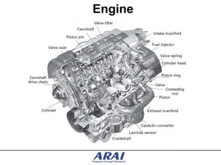
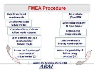
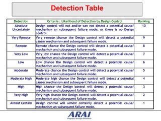
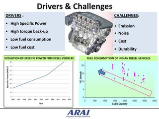
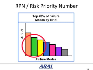
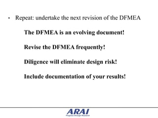
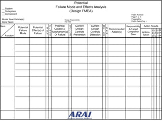
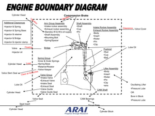
The document discusses failure mode and effects analysis (FMEA) of engine systems to identify potential failures, analyze their causes and effects, and determine corrective actions to improve reliability. It provides details on conducting a DFMEA, including assembling a cross-functional team, documenting functions and potential failure modes, analyzing severity, occurrence, and detection of failures, and calculating a risk priority number. The goal is to iteratively conduct the DFMEA, take corrective actions, and reduce the risk priority numbers to design more reliable engine components and systems.
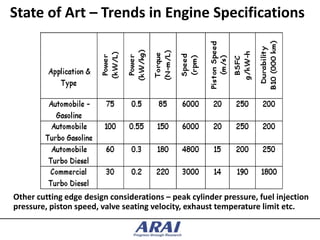
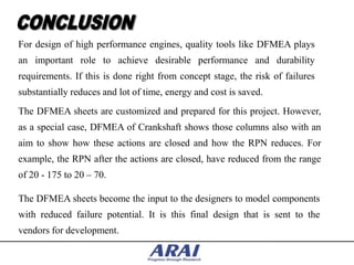
CADmantra Technologies Pvt. Ltd. is one of the best Cad training company in northern zone in India . which are provided many types of courses in cad field i.e AUTOCAD,SOLIDWORK,CATIA,CRE-O,Uniraphics-NX, CNC, REVIT, STAAD.Pro. And many courses
Contact: www.cadmantra.com
www.cadmantra.blogspot.com
www.cadmantra.wix.com
Legal Aspects of FMEA, overview of Canadian Law,
Due Diligence vs Negligence, Criminal Negligenced and what everyone needs to know about duty of care
www.6sengineering.com
Get faster design success eliminating mistakes and proyect bugs by preventive use of DFMEA preventive and corrective actions. Practical experiences and tips
Design Failure Mode and Effect Analysis (DFMEA) is a systematic group of activities used to determine how to recognize and evaluate potential systems, products or process failures.
DFMEA identifies the effects and outcomes of failures, actions that could eliminate or mitigate the failures and provides a historical written record of the work performed.
It is a method used for identifying potential risks introduced in a new or changed design of a product or service.
It analyse the product design before it is released to manufacturing. It identifies design functions, failure modes and their effects on the customer with corresponding severity ranking / danger of the effect.
It also tracks improvements through Risk Priority Number (RPN) reductions by comparing the before and after RPN.
With the increase in global competition, more and more costumers consider reliability as one of their primary deciding factors, when purchasing new products. Several companies have invested in developing their own Design for Reliability (DFR) processes and roadmaps in order to be able to meet those requirements and compete in today’s market. This presentation will describe the DFR roadmap and how to effectively use it to ensure the success of the reliability program by focusing on the following DFR elements.
Improving Rotating Equipment Reliability and Machinery HealthMexxusts
Course Overview:
According to industry reports more than 60% of maintenance costs are spent on equipment wear, tear and failure. This year the Witbank Institute of Technology will be providing training on Improving Rotating Equipment Reliability and Machinery Health to make sure all rotating Equipment functions at its best. Predictably, continuous improvement of reliability by optimizing predictive maintenance for rotating equipment is one of the most important challenges maintenance professionals face today. This three day session course explains The Causes of Rotating Machinery Failures, Precision Maintenance for Rotating Equipment and Machines, Condition Monitoring and Predictive Maintenance, Design of Rotating Equipment and Machines and Root Cause Failure Analysis Procedure.
[Note: This is a partial preview. To download this presentation, visit:
https://www.oeconsulting.com.sg/training-presentations]
Failure Mode & Effects Analysis (FMEA) is a step-by-step approach for identifying all possible failures in a design, a manufacturing or assembly process, or a product or service. The purpose of the FMEA is to take actions to eliminate or reduce failures, starting with the highest-priority ones. FMEA also documents current knowledge and actions about the risks of failures, for use in continuous improvement.
In this training presentation, you can teach your employees on the proper steps to construct an FMEA for a design or process, and then implement action plans to eliminate or reduce the risks of potential failures.
LEARNING OBJECTIVES
1. Understand what an FMEA is, why it is used, and when can it be deployed
2. Understand the definitions, scoring system and calculations used in an FMEA
3. Learn the steps to developing an FMEA and the pitfalls to avoid
CONTENTS
1. Introduction to FMEA
2. FMEA: Definitions, Scoring System & Calculations
3. FMEA Procedure
4. FMEA Example
Authors: (i) Prashanth Lakshmi Narasimhan,
(ii) Mukesh Ravichandran
Industry: Automobile -Auto Ancillary Equipment ( Turbocharger)
This was presented after the completion of our 2 months internship at Turbo Energy Limited during our 3rd Year Summer holidays (2013)
ABOUT THE TRAINING PROGRAM :-
Failure Mode and Effects Analysis or FMEA is a structured technique to analyze a process to determine shortcomings and opportunities for improvement. By assessing the severity of a potential failure, the likelihood that the failure will occur, and the chance of detecting the failure, dozens or even hundreds of potential issues can be prioritized for improvement.
DESIGNED FOR :-
Sr. Engineer, Engineer, Supervisor and Foreman engaged in maintenance, operation, Store, Supply chain, Quality, Safety and Engineering activities.
OBJECTIVE :-
Employees completing this training will be able to effectively participate on an FMEA team and can make immediate contributions to quality and productivity improvement efforts.
The ultimate guide on constructing a FMEA process for Manufacturing, Maintenance, Services and Design.
The presentation include step by step on how to determine the failure modes, failure effects, assign severity, assign occurrence, assign detection, calculate risk priority numbers and prioritize the RPNs for action. With some examples and illustrations.
Presentation contents:
1. Determing failure modes, effects and causes.
2. FMEA team & team leader.
3. Brainstorming.
4. The basic steps of FMEA.
5. Examples.
What is a PPAP (production part approval process) and how does it work? We answer the basic questions about PPAP and how it's used in this presentation.
The cylinder head is a crucial part of engine or combustion chamber which helps to produce energy in a proper measurement for vehicle use. A single crack in cylinder head can give a catastrophic experience on the middle of road or in the traffic. Check the slides here to know the telltale signs of the car cylinder head problems so that you can repair it immediately to avoid any big problem in the future.
FMEA is one of the most commonly used safety and quality analysis procedures used in a variety of industries. It is an inductive bottom-up approach that targets the relevant system, design, software, hardware, production, etc failure modes and evaluates their risks based on their levels of severity, expected occurrence, and detectability/preventive measures.
Learn how to analyze, evaluate and manage the risks during development to avoid systematic failures in your system.
Watch this Expert Series webinar to learn more about Failure Mode and Effects Analysis, and about applying a risk management procedure to ensure the functional safety of your products.
https://intland.com/on-demand-webinar/fmea-risk-management-in-practice/
Introduction to Reliability Centered MaintenanceDibyendu De
Introduces Reliability Centered Maintenance, strategies employed, formulation of effective maintenance plan, reduction of consequences of failures and failure rate.
Armonización de políticas para vehículos ligeros nuevos en América del Norte: Estándares de eficiencia energética, gases de efecto invernadero y contaminantes criterio
7/9/2014-7/10/2014
Mexico City
Is Reliability Centered Maintenance (RCM) right for you?Nancy Regan
This presentation outlines the goals of a Reliability Centered Maintenance (RCM) analysis. It debunks the top misconceptions about RCM. And it poses and answers the top four questions about RCM most people don’t know to ask.
The FMEA relates to a very broad spectrum on how effective this tool can be utilized as solver aid in dealing with the histories/pattern of failure in the product.
And how well can it be hierarchically deal with analysis the root cause of the problem.
This methodology is widely adopted in almost all manufacturing branch industries, due to its efficiency is tracking down all the possibilities occurrence in failure with the severity, occurrence, etc and other parameters to define the intensity of the failure being occurred.
To understand the tools usage a bit further, I have enumerated a case study via a example in this slides.
JPRO Professional Heavy Duty Truck Diagnostic Toolbox User ManualTim Miller
This is the user manual of JPRO Professional Heavy Duty Truck Diagnostic Toolbox.
>> READ MORE: https://www.obdadvisor.com/autel-scanners/
Here is a detailed review of the toolbox based on my own experience, including:
- Compatibility
- Display
- Software
- Features and Functions
- Pros and Cons
Check it out to get the REVIEW and some NOTES about using this tool.
FMEA is a methodical, proactive strategy for assessing a process to determine where and how it might fail as well as to gauge the relative impact of various failures in order to pinpoint the areas of the process that require the greatest improvement. Teams utilise FMEA to assess processes for potential failures and to prevent them by making proactive process corrections as opposed to responding to unfavourable occurrences after failures have happened. With a focus on prevention, there may be a lower chance of injury to patients and staff. FMEA is particularly helpful in assessing the impact of a proposed change to an existing process and in evaluating a new process prior to implementation.
3. FMEA Procedure
List all Function & Re- evaluate
requirements (New RPN )
List all conceivable Define Responsibility
failure modes & Time- frame
Consider effects, if above
Recommend
failure mode happens
improvements
Look possible causes &
mechanism for Calculate the Risk
failures mode Priority Number (RPN)
Assess the frequency of Assess the possibility of
occurrence of Failure being
failure modes (O) detected ( D )
Assess the Severity of effect (s)
5. Occurrence table
Occurrence (o)
Suggested Evaluation Criteria:
Probability of Failure Possible Failure Rates Ranking
Very High : Persistent > 100 per thousand vehicles/ items 10
failures 50per thousand vehicles/ items 9
High : Frequent failures 20 per thousand vehicles/ items 8
10 per thousand vehicles/ items 7
Moderate : Occasional 5 per thousand vehicles/ items 6
failures 2 per thousand vehicles/ items 5
1 per thousand vehicles/ items 4
Low : Relatively few 0.5 per thousand vehicles/ items 3
failures 0.1 per thousand vehicles/ items 2
Remote : Failure is < 0.010 per thousand vehicles/ items 1
unlikely
6. Severity table
Effect Criteria : severity of Effect Ranking
Hazardous Very high severity ranking when a potential failure mode affects safe 10
without vehicle operation and/or involves noncompliance with government
warning regulation without warning.
Hazardous Very high severity ranking when a potential failure mode affects 9
with warning safe vehicle operation and/or involves noncompliance with
government regulation with warning.
Very High Vehicle/ item inoperable (loss of primary function). 8
High Vehicle/ item operable but at reduced level of performance. 7
Customer very dissatisfied.
Moderate Vehicle/ item operable, but Comfort/ Convenience item(s) 6
inoperable. Customer dissatisfied.
Low Vehicle/ item operable, but Comfort/ convenience item(s) operable 5
at a reduced level of performance. Customer somewhat dissatisfied.
Very Low Fit & Finish/ Squeak & Rattle item does not conform. Defect noticed 4
by most customers (greater than 75%).
Minor Fit & Finish/ Squeak & Rattle item does not conform. Defect noticed 3
by 50% of customers.
Very Minor Fit & Finish/ Squeak & rattle item does not conform. Defect noticed 2
by discriminating customer (less than 25%).
None No discernible effect. 1
7. Detection Table
Detection Criteria : Likelihood of Detection by Design Control Ranking
Absolute Design control will not and/or can not detect a potential cause/ 10
Uncertainty mechanism an subsequent failure mode; or there is no Design
control
Very Remote Very remote chance the Design control will detect a potential 9
cause/ mechanism and subsequent failure mode.
Remote Remote chance the Design control will detect a potential cause/ 8
mechanism and subsequent failure mode.
Very Low Very low chance the Design control will detect a potential cause/ 7
mechanism and subsequent failure mode.
Low Low chance the Design control will detect a potential cause/ 6
mechanism and subsequent failure mode.
Moderate Moderate chance the Design control will detect a potential cause/ 5
mechanism and subsequent failure mode.
Moderate High Moderate high chance the Design control will detect a potential 4
cause/ mechanism and subsequent failure mode.
High High chance the Design control will detect a potential cause/ 3
mechanism and subsequent failure mode.
Very High Very high chance the Design control will detect a potential cause/ 2
mechanism and subsequent failure mode.
Almost Certain Design control will almost certainly detect a potential cause/ 1
mechanism an subsequent failure mode.
10. Customer Requirements
• Not just power and speed range
• Not just rated torque but torque profile
• Weight/space
• Fuel economy/emissions/noise
• Duty cycle/durability/reliability
• Service intervals and serviceability
• Cost sensitivity
• Iterations on materials/cost/temperature pressure
capability and target performance
• Upgrade capability
• End of life considerations.
Many methodical techniques such as QFD available for use
11. Drivers & Challenges
DRIVERS : CHALLENGES:
• High Specific Power
• Emission
• High torque back-up • Noise
• Low fuel consumption • Cost
• Low fuel cost • Durability
EVOLUTION OF SPECIFIC POWER FOR DIESEL VEHICLES 25 FUEL CONSUMPTION OF INDIAN DIESEL VEHICLES
20
FC (kmpl)
15
10
5
0
0 500 1000 1500 2000 2500 3000 3500
Cubic Capacity
12. State of Art – Trends in Engine Specifications
Other cutting edge design considerations – peak cylinder pressure, fuel injection
pressure, piston speed, valve seating velocity, exhaust temperature limit etc.
13. • Analyze the engine/components/systems and summarize
various functions and failure modes.
• 50 components and 10 systems to be listed and their functions
and failure modes to be studied.
• 5 out 60 components/systems are picked. DFMEA to be
conducted for these 5 components/systems.
•These components & systems all had failure modes and a
corresponding Risk Priority Number (RPN) to be calculated
using severity, occurrence & detection rankings.
•The idea is to reduce this RPN value so that the
components/systems are designed more towards reliability and
safety. These reductions are to be done through design changes.
14.
15. • FAILURE MODES & EFFECTS ANALYSIS (FMEA) is
a paper-and-pencil analysis method used in engineering to
document and explore ways that a product design might
fail in real-world use.
• Failure Mode & Effects Analysis is an advanced quality
improvement tool.
• FMEA is a technique used to identify, prioritize and
eliminate potential failures from the system, design or
process before they reach the customer.
• It provides a discipline for documenting this analysis for
future use and continuous process improvement.
16. • Historically, FMEA was one of the first systematic techniques for failure
analysis developed by the U.S. Military on 9th November, 1949. FMEA
was implemented in the 1960‟s and refined in the 70‟s. It was used by
reliability engineers working in the aerospace industry.
• Then the Automotive Industry Action Group formed by Chrsyler, Ford &
GM restructured the FMEA techniques which found a lot of importance in
the automotive industry.
• Since then FMEA has been instrumental in producing quality goods in
the automotive sector.
17. • SYSTEM FMEA
- Chassis system
- Engine system
- Transmission
• COMPONENT FMEA
- Piston
- Crankshaft
•PROCESS FMEA
- Involves machine, manufacturing process, materials
18. DFMEA: Starts early in process. It is complete by the time
preliminary drawings are done but before any tooling is initiated.
PFMEA: Starts as soon as the basic manufacturing methods have
been discussed. It is completed prior to finalizing production
plans and releasing for production.
19. MIL-STD 1629, “Procedures for Performing a Failure Mode and Effect
Analysis”
IEC 60812, “Procedures for Failure Mode and Effect Analysis (FMEA)”
BS 5760-5, “Guide to failure modes, effects and criticality analysis (FMEA
and FMECA)”
SAE ARP 5580, “Recommended Failure Modes and Effects Analysis
(FMEA) Practices for Non-Automobile Applications”
SAE J1739, “Potential Failure Mode and Effects Analysis in Design (Design
FMEA)”
SEMATECH (1992,) “Failure Modes and Effects Analysis (FMEA): A Guide
for Continuous Improvement for the Semiconductor Equipment Industry”
20. • They can only be used to identify single failures and not
combinations of failures
• Failures which result from multiple simultaneous faults are not
identified by this
• Unless adequately controlled and focused, the studies can be time
consuming
• They can be difficult and tedious for complex multi-layered systems
• They are not suitable for quantification of system reliability
21. RESPONSIBILITY AND SCOPE OF THE DFMEA
• The DFMEA is a team function
– All team members must participate
– Multi-disciplinary expertise and input is beneficial
• Input from all engineering fields is desirable
• Representatives from all areas (not just technical
disciplines) are generally included as team members
• The DFMEA is not a one meeting activity
– The DFMEA will be refined and evolve with the product
– Numerous revisions are required to obtain the full benefit of
the DFMEA
• The DFMEA must include all systems, sub-systems, and
components in the product design
22. • Form the cross functional team.
• Call FMEA Meeting with advance intimation.
• Complete the top of the form
– Project, year, team members, date, and DFMEA iteration
– There will be many iterations
• List items and functions
– Start with the system, then subsystems and finally components
• Document potential failure modes
– How could the design potentially fail to meet the design intent?
– Consider all types of failure
• Document the potential effects of failure
– How would design potentially fail to meet the design intent?
23. • Rate the severity of the failure effect
– See ranking guidelines
– Severity ranking is linked to the effect of the failure
• Document potential causes and mechanisms of failure
– Failure causes and mechanisms are an indication of design weaknesses
– Potential failure modes are the consequences of the failure causes
– A single failure mode may have multiple failure mechanisms
– Use group brainstorming sessions to identify possible failure mechanisms
– Don‟t be afraid to identify as many potential causes as you can
– This section of the DFMEA will help guide you in necessary design changes
– The output of the DFMEA will indicate on which item to focus design
efforts
24. • Rate the occurrence
– See attached page for ranking guidelines
– Things that may help you rate the occurrence
• Are any elements of the design related to a previous device or design?
• How significant are the changes from a previous design?
• Is the design entirely new?
• List the design controls
– Design controls are intended to:
• Prevent the cause of the failure mode (1st choice solution)
• Detect the cause of the failure mode (2nd choice solution)
• Detect the failure mode directly (3rd choice solution)
– Applicable design controls include
• Predictive code analysis, simulation, and modeling
• Tolerance “stack-up” studies
• Prototype test results (acceptance tests, DOE‟s, limit tests)
• Proven designs, parts, and materials
25. • List any critical or special characteristics
– Critical characteristics: Severity > 8 and Occurrence >1
– Special characteristics: Severity > 6 and Occurrence >2
• Detection rate
– See attached page for ranking guidelines
• Calculate the RPN of each potential failure effect
– RPN = (Severity) x (Occurrence) x (Detection)
– What are the highest RPN items?
• Define recommended actions
– What tests and/or analysis can be used to better understand the problem to
guide necessary design changes ?
26. • Assign action items
– Assemble team
– Partition work among different team members
– Assign completion dates for action items
– Agree on next team meeting date
• Complete “Action Results” Section of DFMEA
– Note any work not accomplished (and the justification for incomplete work)
in the “actions taken” section of the DFMEA.
• Why was nothing done?
– Change ratings if action results justify adjustment, but the rules are:
• Severity: May only be reduced through elimination of the failure effect
• Occurrence: May only be reduced through a design change
• Detection: May only be reduced through improvement and additions in
design control (i.e. a new detection method, better test methodology,
better codes, etc.)
– Include test and analysis results with DFMEA to validate changes.
27. Example of Significant/ Critical Threshold
Special Characteristics Matrix
10 POTENTIAL CRITICAL
9 CHARACTERISTICS Safety/Regulatory
S
E 8 POTENTIAL
V 7 SIGNIFICANT
E 6 CHARACTERISTICS
Customer Dissatisfaction
R 5
I 4 ANOYANCE
T 3 ZONE
ALL OTHER CHARACTERISTICS
Y 2
Appropriate actions /
1 controls already in place
1 2 3 4 5 6 7 8 9 10
OCCURRENCE
28. RPN / Risk Priority Number
Top 20% of Failure
Modes by RPN
R
P
N
Failure Modes
29. • Repeat: undertake the next revision of the DFMEA
The DFMEA is an evolving document!
Revise the DFMEA frequently!
Diligence will eliminate design risk!
Include documentation of your results!
30. Potential
__ System
Failure Mode and Effects Analysis
__ Subsystem (Design FMEA)
__ Component FMEA Number:
Page 1 or 1
Model Year/Vehicle(s): Design Responsibility Prepared by:
FMEA Date (Orig.):
Core Team: Key Date:
Item C Potential O Current Current D Responsibility Action Results
Potential Potential S L C E R. Recommended
Cause(s)/ Design Design & Target
Failure Effect(s) of E A Mechanism(s) C T P. S O D R.
Controls Controls Action(s) Completion Actions
Mode Failure V S U E N.
Date
E C E P.
Function S Of Failure R Prevention Detection C Taken V C T N.
30
31. Cylinder Head Compression Brake
Additional Clearances Arm Group Assembly Shaft Assembly
•Injector & Spring •Intake rocker assembly •Shaft
Intake Rocker Assembly
•Exhaust rocker assembly •Cup Valve Cover
•Injector & Spring Base Exhaust Rocker Assembly
•Stand(s) W & W/o oil supply •Pin
•Body
•Injector & retainer •Shaft Assembly
•Insert
•Injector & Bridge •Mounting Bolt
•Roller
•Spring/Spacer
•Injector & injector clamp •Pin
•Clip
Valve Bridge Lube Oil
Pushrod
•Injector oil •Rod
•Cup
Spring Group •Ball
•Inner & Outer Springs
Cylinder Head •Spring Base
•Retainer/Rotator
•Valve Keeper Lifter Assembly
•Body
Valve Stem Seal
Valve Group •Insert
•Intake Valve •Roller
•Exhaust Valve •Pin
•Intake Seat •Clip
Lube Oil •wire Oscillating Lifter
•Exhaust Seat
•Valve Guide •Pressure Lube
CAM Shaft
Cylinder Head •Valve Guide Seal OR
Bore in Block
Valve Seat CAM Bearings
•Pressure Lube
Seat Insert
Thrust Plate
Cylinder Head
Cylinder Block
32.
33. Tensioner
Cylinder Head Main Hydraulic Lash Rockers
Gallery Adjuster
Vacuum Pump
Orifice
Camshaft
Cam Journal
Cylinder Block Main Gallery
B/Pass Main Bearing Drive &
Oil Filter Turbocharge
Valve No. 1, 2, 3 Tensioner
r
Oil Cooler
Oil Jet Con rod
Oil Pump R/Valve BRG.
No.1, 2, 3
1, 2, 3
Oil Strainer
2 Part Oil PAN with Filter in between
34. • CYLINDER BLOCK
• CYLINDER HEAD
• CYLINDER HEAD GASKET
• VALVES
• PISTON
• CONNECTING ROD
•CRANKSHAFT
• AIR INTAKE SYSTEM
• EXHAUST SYSTEM
• TURBOCHARGER
35. The crankshaft, sometimes casually abbreviated to crank, is the
part of an engine which translates reciprocating linear piston
motion into rotation. To convert the reciprocating motion into
rotation, the crankshaft has "crank throws" or "crankpins",
additional bearing surfaces whose axis is offset from that of the
crank, to which the "big ends" of the connecting rods from each
cylinder attach.
36. • Crankshaft literature Survey
• Crankshaft functions/requirement
• Crankshaft benchmarking
• Visit to vendors place for understanding production process
• Crankshaft concept development
• Crankshaft failure modes
• Design FMEA at vendor’s place
• Crankshaft model
• Classical strength analysis
• Excite strength analysis
• Factor of Safety analysis
• Crankshaft draft drawing
• Sending draft drawing & filled questionnaire to vendor
• Preliminary Design Review with vendor
• Finite Element Analysis by vendor & web optimization
• Material & Heat Treatment discussions
• Closing Design FMEA
• Quotation & Purchase Order
• Process FMEA at vendor’s place
• Die making & production
37. • Convert reciprocating motion of piston to rotary motion
• Transfer energy from engine
• Requires Balancing (In case of 3 cylinder, primary &
secondary couples can be balanced by Balancer shaft,
Rotary couples needs to be balanced by counterweight
optimization)
• Defines piston Travel
• Requires resistance to fatigue (Weak points at the fillet
radius)
• Requires resistance to alternating torsion (Oil holes are
weak points)
38. • Should withstand forces - gas pressure, rotating and
reciprocating inertia
• Should withstand vibratory forces
• Should damp torsional vibrations
• Requires infinite life under high cycle bending
• Requires friction & wear reduction at the bearings
• Requires smooth grain flow through critical regions
• Requires high strength to weight ratio
(Stress increases by 4 times for every doubling of speed)
39. • High cycle bending at webs, nose & flywheel flange
• Galling fillets (Similar to Adhesive wear)
• Radii fracture (at pin & journal)
• Scored bearing journals
• Bends, warpage and cracks
• Abrasive wear
• Chipping
•Torsional failure
• Bearing failure
40.
41.
42. • Major Input Data (at Max BMEP operating point) :-
Sr. No. Parameter Value
1 Main Brg Centre Distance [mm] 100.oo
2 Section modulus of left crank web [mm3] 2008.63
3 Section modulus of Right crank web [mm3] 2008.63
4 Thickness of left and right webs [mm] 20.5
5 Eq length of left crank web [mm] 116.00
6 Eq length of right crank web [mm] 116.00
7 Crank pin / main journal fillet radius [mm] 3.5
8 Material of Crankshaft (Present ) 30CrNiMo8
9 UTS crankshaft material [N/mm2] 1250
10 Fatigue Strength of CS material [N/mm2) 510
11 Engine Speed [rpm] 2000
43. No. Position Amplitude Mean
stress Stress
(N/mm2) (N/mm2)
1 Left Crank pin 239.34 217.05
2 Right Crank pin 239.34 217.05
3 Left Main journal 330.20 299.44
4 Right Main journal 330.20 299.44
44. SAFETY FACTORS
-------------------------------------------------------
CRANK PIN MAIN JOURNAL
FILLET FILLET
LEFT RIGHT LEFT RIGHT
-------------------------------------------------------
1.90 1.90 1.65 1.65
-------------------------------------------------------
2
1.8
1.6
1.4 PERMISSIBLE FOS
1.2 CRANKPIN FILLET LEFT
1 CRANKPIN FILLET RIGHT
0.8 JOURNAL PIN FILLET LEFT
0.6 JOURNAL PIN FILLET RIGHT
0.4
0.2
0
1
48. MAIN BEARING OFT UPPER SHELL (in mm)
No. MAIN BEARING 1 MAIN BEARING 2 MAIN BEARING 3 MAIN BEARING 4
2000 0.0075 0.02 0.0045 0.0075
4200 0.004 0.004 0.0037 0.004
MAIN BEARING OFT LOWER SHELL (grooved)
No. MAIN BEARING 1 MAIN BEARING 2 MAIN BEARING 3 MAIN BEARING 4
2000 0.00225 0.002 0.00175 0.0022
4200 0.0024 0.00185 0.0015 0.0024
BIG END BEARING OFT UPPER SHELL (grooved)
No. BIG END BEARING 1 BIG END BEARING 2 BIG END BEARING 3
2000 0.001 0.001 0.001
4200 0.0014 0.0014 0.0014
BIG END BEARING OFT LOWER SHELL
No. BIG END BEARING 1 BIG END BEARING 2 BIG END BEARING 3
2000 0.007 0.007 0.007
4200 0.002 0.002 0.002
Desirable OFT ≥ 0.001 mm ( 1 micron ) for conventional bearings
≥ 0.0003 mm ( 0.3 micron ) with sputter bearings
49. 3-layer-bearing
Steel backing
bronze layer
intermediate layer
(Ni if nessesary)
running layer
(sputtered, electroplated,
sprayed)
The sputtering process produces a material that combines the high wear-resistance
properties of an aluminum-tin sliding layer with the extremely high-load
withstanding capacity of a cast copper-lead-bearing metal layer.
50. 2000 rpm 4200 rpm
ORDER PULLEY PULLEY
0.5 0.063 0.049
1 0.094 0.084
1.5 2 0.3
Torsional resonance is visible between 4.5 and 6th
2 0.057 0.02 order i.e corresponding speed range of 3345 to
2.5 0.0635 0.064 4460 rpm. Since this falls within operating speed
3 0.2 0.01
3.5 0.05 0.074 range, a TV damper is MUST.
4 0.042 0.08
PULLEY END TV AMPLITUDES
4.5 0.03 0.32
5 0.002 0.65 2.5
5.5 0.03 0.08 MAGNITUDE 2
6 0.02 0.09 1.5
6.5 0.0235 0.02 1
7 0.0215 0.013 0.5
0
7.5 0.03 0.025
1
2
3
4
5
6
7
8
9
10
11
12
0.5
1.5
2.5
3.5
4.5
5.5
6.5
7.5
8.5
9.5
10.5
11.5
8 0.02 0.007
8.5 0.02 0.006 ORDER
9 0.04 0.01 PULLEY END AMPLITUDES @ 2000 rpm PULLEY END AMPLITUDES @ 4200 rpm
9.5 0.025 0.005
10 0.06 0.001
10.5 0.19 0.06
11 0.019 0.002
11.5 0.01 0.001
12 0.014 0.002
52. The three main potential failure modes are:
• Crankshaft fracture
• High noise & vibration
• Bearing wear & failure
As we know, the crankshaft is a component which takes a lot of
stresses and vibrations. The entire gas force is transferred to the
crankshaft. So when failure modes such as fracture occur, the
engine stalls and this is a potential effect of failure. Other
observations made are those caused due to vibrations. There can
be loosening of fasteners, extreme vibrations throughout the
vehicle and lower the life of engine mounts.
53. • Micro alloyed steel is the material that will be used to develop
the crankshaft. Stress risers generate from the sharp edges and
therefore fillets are crucial in a crankshaft design. The fillet
radius is an important parameter and here the CAE analysis is
carried out with different fillet radii and the final radius is
calculated.
• Noise and vibration is optimized by modal testing where the
component is checked for resonance between the operating
engine RPM.
• Surface treatment is vital too.
• Induction hardening is done on the crankshaft to improve the
ultimate tensile strength and fatigue bending strength.
54. For design of high performance engines, quality tools like DFMEA plays
an important role to achieve desirable performance and durability
requirements. If this is done right from concept stage, the risk of failures
substantially reduces and lot of time, energy and cost is saved.
The DFMEA sheets are customized and prepared for this project. However,
as a special case, DFMEA of Crankshaft shows those columns also with an
aim to show how these actions are closed and how the RPN reduces. For
example, the RPN after the actions are closed, have reduced from the range
of 20 - 175 to 20 – 70.
The DFMEA sheets become the input to the designers to model components
with reduced failure potential. It is this final design that is sent to the
vendors for development.
55. • “Potential Failure Mode & Effects Analysis (FMEA)” – Reference
Manual, Chrysler, Ford & G.M, Issued, First Edition February 1993
• D.H. Stamatis, “Failure Modes and Effects Analysis”, Productive Press,
1997
• SAE Standard „SAEJ1739‟ – Failure Modes & Effects Analysis
• www.wikipedia.com (http://en.wikipedia.org/wiki/DFMEA)
• Kevin Hoag, “Vehicular Engine Design”, Springer Wien New York,
2006
• Richard Basshuysen, Internal Combustion Engine – Handbook, SAE
International
• Hiroshi Yamagata, The Science and Technology of materials in
automotive engines, Woodhead Publishing Limited