This document discusses using design failure mode and effects analysis (dFMEA) to improve quality function deployment (QFD) and the theory of inventive problem solving (TRIZ) for computational simulation of component durability. It provides background on dFMEA processes and outlines how dFMEA can be applied to optimize durability simulation by considering potential failure modes and their causes early in the design process. Robustness tools like p-diagrams and boundary diagrams are also discussed as complementary to dFMEA for preventing failures through robust design.
DMAIC addressed Bearnson S-N tracking for all product.Bill Bearnson
1) The document describes the DMAIC process for continuous improvement. It consists of five steps: Define, Measure, Analyze, Improve, and Control.
2) An example project at L-3 CSW aimed to track configurations of delivered products to reduce rework, diagnose issues more quickly, and improve service. They lacked a centralized database to record hardware changes.
3) The root cause was high production demand requiring faster turnaround times. Records of configurations and changes were kept in multiple places, causing delays and redundant work to diagnose returned units. The project combined data from five sources into a searchable master database to improve traceability of configurations.
This document provides guidance on conducting a Design Failure Mode and Effects Analysis (Design FMEA). It outlines the purpose and scope of a Design FMEA, how it relates to System and Process FMEAs, and how to implement and document a Design FMEA. Key aspects include conducting the FMEA as a cross-functional team effort, using a standard form to document potential failures, causes, effects, and actions, and ensuring follow-up to implement recommended actions. The goal is to reduce risk by considering potential failures early in the design process.
This document provides an overview of software configuration management (SCM) concepts and definitions. It discusses SCM as the discipline for systematically controlling changes to software systems throughout the software life cycle. The key activities of SCM are identified as configuration identification, configuration change control, configuration status accounting, and configuration auditing. Baselines, configuration items, and the importance of SCM are also summarized.
To achieve success in any project domains, measures of progress to plan are needed in units meaningful to the decision-makers. These include cost, schedule, and technical performance
This document summarizes key aspects of project planning and estimation techniques discussed in a lecture. It covers topics like plan-driven vs agile development, project scheduling, estimation models like COCOMO II, and factors that affect estimation accuracy. Project planning involves breaking work into tasks, scheduling, and communicating the plan. Estimation can be experience-based or use algorithmic models factoring in attributes like size, team experience, and complexity.
Informing Program Performance with Technical Performance Measures (TPMs)Glen Alleman
This Handbook provides guidance to Government Program Managers and Program Performance Analysts for identifying, integrating, managing and assessing the impacts on program performance from Technical Performance Measures (TPMs).
CMMI - High Maturity Misconceptions and PitfallsRajesh Naik
This document discusses high maturity process implementation and common pitfalls. It begins by outlining the agenda, which includes process performance models, sub-process control, managing process improvements, and typical misconceptions and pitfalls. It then discusses how process performance models are complex because reality is complex, and outlines simplifications commonly made. It also notes that outcomes of complex processes are difficult to intuitively predict. The document concludes by identifying common issues seen in implementing high maturity practices and what should be seen in future high maturity implementations to address these issues.
Lightweight processes are beginning to replace more formal methods. The motivation for this transition is based on many factors. The Internet, time to market, cost reduction, quality increases, market pressures, as well as the popularization of these programming methods. This series of articles will investigate the various lightweight methods, their impact on the management of software development projects and the processes by which managers can determine the appropriateness and usefulness of the various processes. The definition of a lightweight Process is more difficult than it would first appear. This article outlines the foundations of a heavyweight process and describes the appropriate pieces that can be converted to lightweight.
This chapter discusses project integration management, which involves coordinating all aspects of a project throughout its life cycle. It describes developing a project charter, preliminary scope statement, and project management plan. It also covers executing the project according to the plan, monitoring progress, and making any necessary changes. Project selection methods like financial analysis and weighted scoring are presented to help organizations choose the right projects to implement.
This document discusses software project management. It defines software project management and outlines some key aspects of the software development process including requirements management, risk management, change management, software configuration management, and release management. It also discusses project planning, monitoring, and control. The document concludes that the future of the project management software industry looks promising due to increased demand from infrastructure and other projects funded by economic stimulus programs around the world.
The Practical Software Measurement (PSM) Process provides a framework for implementing an effective software measurement process. It involves three key activities: 1) tailoring measures to the specific project, 2) applying measures by collecting and analyzing data, and 3) implementing the measurement process within the organization. The goal is to provide objective information to support project management decisions regarding cost, schedule, and technical objectives. PSM is a flexible, issue-driven process based on measurement best practices.
This document provides an overview of failure mode and effects analysis (FMEA). It defines FMEA as a technique used to identify, analyze, and prevent potential failures. The document outlines the history and evolution of FMEA, describes the different types of FMEA (design, process, etc.), and explains the basic steps to develop an FMEA, including defining the system, identifying failures and their causes/effects, calculating risk priorities, and selecting actions. The overall purpose of FMEA is to reduce risks and improve reliability.
Innovative Approach to FMEA FacilitationGovind Ramu
This document discusses an innovative approach to facilitating failure mode and effects analysis (FMEA). It provides background on the history and traditional approach to FMEA, then outlines an improved approach using brainstorming software, cause-and-effect diagrams, and a focus on identifying root causes and prioritizing corrective actions. Key aspects of the new approach include utilizing cross-functional teams, observing processes first-hand, quantifying severity, occurrence, detection ratings, and regularly reassessing FMEA findings as improvements are made.
The document provides an overview of software cost estimation, outlining various methods used including algorithmic models like COCOMO, expert judgement, top-down and bottom-up approaches, and estimation by analogy. It discusses COCOMO in detail, including the original COCOMO 81 model and updated COCOMO II model, and emphasizes the importance of calibration for accurate estimates.
The document provides an overview of the Define-Measure-Analyze-Improve-Control (DMAIC) methodology, which is Six Sigma's most common problem-solving approach. It consists of five steps: Define the problem, Measure current performance, Analyze to find the root cause, Improve by implementing a solution, and Control to ensure continued benefits. The approach aims to reduce variation and bring processes back into alignment with customer requirements. Key requirements that determine the methodology's activities include understanding the problem definition, current metrics and their trends, identifying root causes, implementing corrective actions, and controlling improvements over time.
Changes in CMMI-DEV and SCAMPI-A v1.3 - An Implementation PerspectiveRajesh Naik
This document summarizes the changes made in version 1.3 of the CMMI®-DEV and SCAMPISM models and methodologies. It outlines the agenda which includes changes to generic goals and practices, as well as changes at different maturity levels. Key changes include removing generic goals 4 and 5, shifting requirements management to the project management category, adding additional specific practices, and renaming and modifying some process areas. The document also provides an overview of the CMMI®-SVC model and how it can be applied to different service domains.
This document provides an overview of the project initiation and planning process for systems development projects. It describes the key deliverables and outcomes of this process, including developing a business case, baseline project plan, and project scope statement. It also covers assessing project feasibility from economic, technical, operational, scheduling, legal and other standpoints. Methods for evaluating project benefits, costs, risks and determining economic feasibility like cost-benefit analysis are explained. The time value of money concepts and techniques for reviewing and finalizing the baseline project plan like structured walkthroughs are also outlined.
The document provides solutions to exercises from the textbook "Software Engineering 9th edition". It begins with a preface explaining that the solutions manual is intended to help teachers mark student homework and that answers are only provided for about half the exercises. For exercises without answers provided, the preface gives reasons such as the answers being in the text, there being multiple valid solutions, or the questions being intended to stimulate discussion. The solutions provided are meant as a guide and teachers should reward students' credible answers that show thought and knowledge.
Smith Systems Consulting has been tasked with developing standardized project documentation and testing procedures. They propose using an Agile development methodology called Scrum. Key aspects of their proposal include defining stakeholders, conducting requirements analysis, implementing a strict change control process, and performing various testing stages. They recommend replacing outdated hardware and software at Kudler Fine Foods locations with newer Windows systems. The goal is to develop a customer rewards program to increase satisfaction and loyalty.
This document summarizes key aspects of process improvement discussed in two lectures. It discusses the process improvement process, including process measurement, analysis, and change. It describes approaches like the CMMI framework and how it is used to assess process maturity levels. It outlines the stages of process change and challenges like resistance to change.
The use of an architecture–centered development process for delivering information technology began with the introduction of client / server based systems. Early client/server and legacy mainframe applications did not provide the architectural flexibility needed to meet the changing business requirements of the modern manufacturing organization. With the introduction of Object Oriented systems, the need for an architecture–centered process became a critical success factor. Object reuse, layered system components, data abstraction,
web based user interfaces, CORBA, and rapid development and deployment processes all provide economic
incentives for object technologies. However, adopting the latest object oriented technology, without an adequate understanding of how this technology fits a specific architecture, risks the creation of an instant legacy
system.
1. Software project estimation involves decomposing a project into smaller problems like major functions and activities. Estimates can be based on similar past projects, decomposition techniques, or empirical models.
2. Accurate estimates depend on properly estimating the size of the software product using techniques like lines of code, function points, or standard components. Baseline metrics from past projects are then applied to the size estimates.
3. Decomposition techniques involve estimating the effort needed for each task or function and combining them. Process-based estimation decomposes the software process into tasks while problem-based estimation decomposes the problem.
This is chapter 3 of ISTQB Advance Test Manager certification. This presentation helps aspirants understand and prepare the content of the certification.
MSF is an iterative process model used by Microsoft for project management. It consists of envision, planning, and development phases. In the envision phase, requirements are identified and the overall project direction is agreed upon. In the planning phase, detailed plans are created for what will be delivered and a schedule is established. Functional specifications are documented and validated. The development phase consists of iterative development where functionality is added incrementally in versions until the project is complete.
This document discusses software quality metrics and the costs of software quality. It describes the classic model which classifies quality costs into costs of control (prevention and appraisal) and costs of failure of control (internal and external failures). Prevention costs include investments in infrastructure and regular quality activities. Appraisal costs cover reviews and testing. Internal failures are errors found before release, while external failures are found after. The document provides examples and estimates for various quality metrics.
Phase gate review development model august 8 2017 - dave litwillerDave Litwiller
Phase gate review R&D process model, including detailed description of phases and gates. Suitable for complex hardware, aerospace, embedded systems and architecture-intensive software development.
The document discusses proposed changes to the CMMI model for high maturity practices. It describes an approach used to solicit feedback on draft proposed changes from SEI authorized individuals. Feedback was collected using "ATLAS" (Ask The Lead AppraiserS) and potential changes were rated. Several specific proposed changes to the OPP, QPM, CAR and OID process areas are presented, including revising practices, goals and adding new practices. The changes aim to better align the model with SEI training courses and appraisal methods for high maturity organizations.
La caza del tesoro es un tipo de actividad didáctica que utilizan los docentes para integrar Internet en el currículo. Consiste en una hoja de trabajo y enlaces web que guían a los estudiantes a encontrar información sobre un tema específico. Las cazas del tesoro promueven la adquisición de conocimientos, desarrollan habilidades de búsqueda en Internet y mejoran la comprensión lectora. Los docentes pueden crear cazas del tesoro sobre cualquier tema del currículo, y son una actividad divertida y formativa para los
Gleaux 5K & Fun Run Flyer 2015 _ AdvertisementLaura Brumbaugh
The St. Martin Parish 4-H Healthy Living Advisory Committee is hosting the second annual glow-in-the-dark 5K race and family 1 mile fun run in downtown Breaux Bridge on March 7, 2015. Registration for both the 5K race and fun run begins at 3:00 pm at the 4-H office. The family fun run starts at 5:00 pm and the 5K race starts at 6:00 pm. Participants are encouraged to wear glow sticks, lights, costumes, and anything else that glows. After the races, there will be educational booths, games, prizes, and an awards ceremony in Veteran's Park. Proceeds benefit the St. Martin Parish 4-H Program.
The skylights at a metal fabrication shop in Butler, WI were aged and cracking, with small holes from animals, debris or traffic. Previous asphalt repairs were failing. The skylights were pressure washed, cracks and holes filled with silicone, a base coat applied to block asphalt oils, and then a thick coat of white silicone to encapsulate and protect the substrate for 20 more years of use. This new silicone approach successfully solved the water penetration issues that previous roofing companies were unable to fix.
Types of Renewable energy
Mix of Renewable Energy in the world
Solar Energy
Scope of Solar energy
Solar Technologies
Applications, Benefits and Drawbacks
Conclusion
The document summarizes an automated medical records disc publishing solution called DISCO. It automates the process of fulfilling medical record requests and audit requests by loading, burning, encrypting, and tracking patient records onto permanently labeled discs. Key benefits include dramatically streamlining the workflow, eliminating manual processes and human errors, providing centralized tracking for HIPAA compliance, and realizing significant cost savings through reduced supplies and staff time.
Este documento relata o caso de um paciente de 19 anos com 10 dentes supranumerários. O paciente não apresentava síndrome. Foi realizada exodontia dos 10 dentes sob anestesia geral. A discussão trata da importância do diagnóstico precoce de dentes supranumerários e do tratamento cirúrgico adequado para prevenir problemas futuros.
1) El documento habla sobre marketing de servicios en el sector de tecnología, procesamiento de datos y aplicaciones de software.
2) Se mencionan algunas ventajas para este sector como exenciones de IVA y oportunidades que abrirá una nueva ley de protección de datos.
3) También presenta ejemplos de exportaciones peruanas de servicios como centros de contacto y datos sobre exportaciones de lúcuma.
The Eiffel Tower was built in Paris for the 1889 World Exhibition celebrating the French Revolution. It was almost torn down in 1909 but was saved by its use for telegraphy. The iconic lattice structure is made of iron and took over two years to construct using 12,000 pieces. It remains open to visitors every day of the year.
Las políticas públicas en Venezuela se han manipulado y utilizado con fines populistas por parte de los políticos, lo que ha llevado a empobrecer al país en lugar de ayudar a la población. A lo largo de la historia de Venezuela, los modelos estructuralista, neoliberal y populista aplicados a las políticas públicas han fracasado en lograr objetivos como erradicar la pobreza y mejorar la economía y sociedad. Mientras que las políticas públicas deben crearse para beneficiar a la población, en Venezuela sus debilidades como la falta
Spyros Ktenas
Project Management for Software Development Projects
KTH Royal Institute of Technology
This is the part of the slides relevant to
GE.SI.PMF – Generic Simple Project Management Framework
Doesn’t include PM tools, risk, communication, stakeholders,
PRINCE2, PMBok etc.
Gerenciamento de Projetos SAP: Do Método a PráticaProjetos e TI
É de conhecimento que realizar a gestão de projetos é uma tarefa árdua, principalmente quando se trata de projetos de tecnologia, o que falar então da gestão de implantação de ferramentas relacionadas ao ERP SAP?
Para sanar suas dúvidas vamos contar com quem entende do assunto! Convidamos Rodrigo Silva que irá abordar as Etapas do Gerenciamento de Projetos utilizando a metodologia SAP ASAP, com passagens pelos principais artefatos, discutindo os pontos de atenção para entrega de valor aos clientes.
Link para o Webinar - https://goo.gl/NM0EPX
The document provides an overview of Failure Modes and Effects Analysis (FMEA). [1] FMEA is a methodology used to anticipate potential failures, determine their effects, and identify actions to address failures.[2] It allows engineers to design reliability into products and processes early in development. [3] FMEAs should be conducted whenever failures could harm users and updated throughout development as designs change.
This document provides an overview of Failure Modes and Effects Analysis (FMEA). FMEA is a methodology used to identify potential failures, determine their causes and effects, and identify actions to address failures. It is done early in the design process to improve reliability. Key aspects of FMEA include identifying failure modes and ranking their severity and likelihood. FMEA is an iterative process that helps engineers design out failures and produce reliable products.
This document provides an overview of failure mode and effects analysis (FMEA). It describes FMEA as a tool to identify potential failure modes, estimate the risk associated with failures, and prioritize actions to address high-risk failures. The document outlines the FMEA process, which involves identifying failure modes and their causes and effects, then calculating a risk priority number to prioritize issues. It also discusses design and process FMEAs and when each is used. Finally, it reviews how FMEA relates to and can be used along with other process analysis tools.
The document discusses Failure Mode and Effects Analysis (FMEA) as part of the Six Sigma methodology. It explains that FMEA is implemented during the "Analyze" phase of the DMAIC cycle to help identify process tasks and product features that are prone to failure. The document then outlines the steps for conducting an FMEA, including compiling a failure list, determining failure impacts and rates, establishing detection probabilities, and developing action plans to address high-risk failures. It stresses that FMEA is a priority tool to improve business processes by enabling teams to proactively identify and eliminate likely defects before they impact customers.
This document discusses reliability engineering and how it fits within the system engineering lifecycle. It provides an overview of reliability engineering processes and tools used to optimize risk for projects. Some key points made include:
- Reliability engineering exists to help design out failure modes and reduce operational risk through a partnership with system engineering teams.
- Reliability processes are applied throughout the project lifecycle from requirements development through operations and disposal. Tools include FMEA, FTA, simulation, testing and data analysis.
- The goal is for engineers to think about both success space (how things work) and failure space (how things can fail) to design out failures and ensure mission success.
The document discusses five core quality tools: APQP (Advanced Product Quality Planning), FMEA (Failure Modes and Effects Analysis), PPAP (Production Part Approval Process), MSA (Measurement Systems Analysis), and SPC (Statistical Process Control). It provides a brief overview of each tool, noting that APQP is used to develop products that satisfy customers, FMEA ensures potential problems are considered, PPAP ensures products meet specifications, MSA assesses measurement systems, and SPC enables process control and improvement. The document emphasizes that these five tools are considered core tools for quality management.
This document discusses various software process models, including:
- Waterfall model - A linear sequential model that emphasizes documentation and rigid phases.
- Prototyping model - Allows requirements to change by building prototypes to understand needs.
- RAD (Rapid Application Development) model - Emphasizes short development cycles using reusable components.
- Incremental model - Applies phases in a staggered way, allowing extensions at each step.
- Spiral model - Organizes activities as a spiral with risk reduction and prototype evaluations.
- Component-based model - Focuses on reusing pre-existing software components.
Software testing and introduction to qualityDhanashriAmbre
The document provides an overview of software testing and quality assurance. It defines software testing as a process to investigate quality and find defects between expected and actual results. Testing is necessary to ensure software is defect-free per customer specifications and increases reliability. The document then discusses types of errors like ambiguous specifications, misunderstood specifications, and logic/coding errors. It outlines the software development life cycle including phases like planning, analysis, design, coding, testing, implementation, and maintenance. Each phase is described in 1-2 sentences.
IRJET- Development Operations for Continuous DeliveryIRJET Journal
This document discusses development operations (DevOps) and continuous delivery practices. It describes how various automation tools like Git, Gerrit, Jenkins, and SonarQube are used together in a DevOps pipeline. Code is committed to a version control system and reviewed. It is then built, tested, and analyzed for quality using these tools. Machine learning algorithms are used to classify build logs and determine if builds succeeded or failed. This helps automate the testing process. Static code analysis with SonarQube also helps maintain code quality. The document demonstrates how such automation practices in DevOps can save time and reduce errors compared to manual processes.
The document proposes updated definitions for technology, manufacturing, and services readiness levels based on lean product development principles. It argues the current definitions promote a flawed "build-test-fix" approach and presents alternative "Lean TRL", "Lean MRL", and "SRL" definitions grounded in robust design, design for six sigma, and lean principles. The updated levels aim to characterize and validate performance earlier to reduce costly late iterations compared to the conventional approach.
This document provides an overview of design failure mode and effects analysis (DFMEA). It begins with an introduction to DFMEA, including its purpose and importance in identifying potential failures early in the design process. It then covers key aspects of conducting a DFMEA such as identifying failure modes and their causes and effects. It also discusses how to analyze and prioritize potential failures using a risk priority number based on severity, occurrence, and detection ratings. The document provides examples of how these aspects are evaluated in a DFMEA. It concludes with emphasizing the role of DFMEA in guiding necessary design changes to improve reliability, safety and quality.
The document discusses various software engineering methodologies including the waterfall model, iterative model, Rational Unified Process (RUP), and agile methodologies like extreme programming (XP) and Scrum. It provides detailed descriptions of each methodology's phases and workflows. The waterfall model divides the life cycle into sequential phases while iterative models allow revisiting previous phases. RUP includes inception, elaboration, construction, and transition phases. Agile prioritizes customer satisfaction, working software, and flexibility over documentation and processes.
This document provides an overview of Failure Mode and Effect Analysis (FMEA). FMEA is a systematic process used to evaluate potential failures in products or processes. It involves identifying possible failures, analyzing their causes and effects, and prioritizing issues based on severity, occurrence, and detection. The document discusses different types of FMEAs, key features like reliability determination and failure detection, advantages, and the typical structure and contents of an FMEA document/form.
The ultimate guide on constructing a FMEA process for Manufacturing, Maintenance, Services and Design.
The presentation include step by step on how to determine the failure modes, failure effects, assign severity, assign occurrence, assign detection, calculate risk priority numbers and prioritize the RPNs for action. With some examples and illustrations.
Presentation contents:
1. Determing failure modes, effects and causes.
2. FMEA team & team leader.
3. Brainstorming.
4. The basic steps of FMEA.
5. Examples.
The document discusses several software engineering process models. It begins by defining a generic process model with five framework activities: communication, planning, modeling, construction, and deployment. It then describes different types of process flows (linear, iterative, evolutionary, parallel). Next, it discusses prescriptive process models in more detail, including the waterfall model, incremental process models, and evolutionary models like prototyping and spiral. For each model, it provides an overview and highlights advantages and disadvantages.
This document presents a case study on optimizing manufacturing test times for printed circuit boards using the DMAIC (Define, Measure, Analyze, Improve, Control) process at a Cisco manufacturing facility. The optimization project reduced advance flying probe test times by over 50% without compromising product quality. Statistical analysis over 6 months confirmed the time savings. The test time optimization provided a significant return on investment. The case study demonstrates how DMAIC can be effectively used for manufacturing process improvement.
The document provides an overview and agenda for a training on Failure Mode and Effects Analysis (FMEA). It discusses the history and purpose of FMEAs, how they are used to systematically identify and prevent potential failures in products and processes, and the benefits of conducting FMEAs. The training will cover both Design FMEAs (DFMEA) and Process FMEAs (PFMEA) and include exercises for participants to work through.
Ch 7 integrating quality activities in the projectlife cycleKittitouch Suteeca
The document describes Kittitouch S.'s software engineering course covering various topics:
- Software development methodologies like waterfall, prototyping, spiral, and object-oriented models.
- Factors affecting quality assurance activities and models for quality assurance planning.
- Key software engineering concepts like verification, validation, and qualification.
- A model for evaluating the effectiveness and costs of software quality assurance plans and defect removal activities.
The document includes three revisions by Kittitouch between January and May 2012 with added topics in each revision.
The document discusses different approaches to systems building, including the traditional systems lifecycle model consisting of definition, feasibility, design, development, testing, implementation, evaluation and maintenance phases. It also covers prototyping, using application software packages, end-user development, outsourcing, structured methodologies, object-oriented development, computer-aided software engineering and software reengineering.
The document discusses process models in software engineering. It defines process models as a framework that defines the typical activities, actions, and tasks required to build high-quality software. Process models provide stability, control, and organization to the software development process. The document discusses the key components of a generic process model, including the five framework activities of communication, planning, modeling, construction, and deployment. It also discusses process flows, task sets, process patterns, process assessment, and prescriptive process models.
2. Page 2 of 11
Figure 1 – typical input to a Design FMEA (DFMEA).
The Quality History is always an important input. Past quality issues need close attention to prevent
reoccurrence.
DFMEA [2] [3] [5] is a thorough and detail analysis of the potential failure modes (soft and hard
failures) related to the system primary functions and interface functions. DFMEA is the primary document for
capturing tests that are required to demonstrate we have avoided mistakes. It analyzes and prioritizes the effects
and causes of failure mode actions. DFMEA [5] [6] identifies current controls and additional actions to reduce
associated risks.
As a complementary effort includes: P-Diagram – identifies and documents the input signal(s), noise
factors, control factors, and error states as associated with the ideal function(s).
The following process elements/tools may provide input to the DFMEA [1] [5] [6]:
• Legal requirements.
• QFDs.
• Historical performance information.
• Benchmarking data.
• P-Diagram.
• Control Factors may help in identifying Design
• Controls or Recommended Actions.
• Boundary Diagram and Interface Matrix.
• Intended outputs as Functions.
• System interactions may help in identifying Cause(s) of Failure.
3. Page 3 of 11
There are three basic cases for which FMEAs [1] [3] [5] [7] are generated, each with a different scope or
focus:
Case 1: New designs, new technology, or new process. The scope of the FMEA is the complete design,
technology or process.
Case 2: Modifications to existing design or process (assumes there is a FMEA for the existing design or
process). The scope of the FMEA [1] [3] [5] [7] should focus on the modification to design or process, possible
interactions due to the modification, and field history.
Case 3: Use of existing design or process in a new environment, location or application (assumes there is
an FMEA for the existing design or process). The scope of the FMEA is the impact of the new environment or
location on the existing design or process.
In function of the general industry trend to continually improve products and processes whenever
possible, using the FMEA [1] [3] [5] [7] as a disciplined technique to identify and help minimize potential
concern is as important as ever. Studies of vehicle campaigns have shown that fully implemented FMEA
programs could have prevented many of the campaigns.
One of the most important factors for the successful implementation of an FMEA [2] [4] [6] program is
timeliness. It is meant to be a "before-the-event" action, not an "after-the-fact" exercise. To achieve the greatest
value, the FMEA [5] [6] must be done before a product or process Failure Mode has been incorporated into a
product or process. Up front time spent properly completing an FMEA, when product/process changes can be
most easily and inexpensively implemented, will minimize late change crises. An FMEA [1] [4] can reduce or
eliminate the chance of implementing a preventive/corrective change, which would create an even larger
concern. Communication and coordination should occur between all types of FMEAs.
FMEA PURPOSES
• Improves the quality and reliability of the evaluated products/processes.
• Reduces product redevelopment timing and cost.
• Documents and tracks actions taken to reduce risk.
• Aids in the development of robust control plans.
• Aids in the development of robust design verification plans.
• Helps engineers prioritize and focus on eliminating/reducing product and process concerns and/or helps
prevent problems from occurring.
• Improves customer/consumer satisfaction.
A series of FMEAs [1] [3] [5] [7] completed according to the best practice could act on the noise factors
shown in this illustration. A best practice FMEA series might be described as:
• Doing FMEAs at the right time.
• Considering all interfaces and "noise factors" (shown on a P-Diagram and Interface matrix).
• Starting FMEAs at the system level and cascading information and requirements down to Component
and Process FMEAs.
• Using appropriate Recommended Actions to mitigate risk.
4. Page 4 of 11
• Completing all Recommended Actions in a timely manner.
Preventing mistakes and improving robustness are two distinct, but complementary efforts in failure
mode avoidance. Each of them has its own focus and strength.
For example, some of the key tasks are:
Boundary Diagram – Defines the system boundary/scope and clarifies the relationship between the
focused system and its interfacing systems.
Interface Matrix – Identifies system interfaces and both the effects of interfaces to the focused system
and the interfacing systems. It documents system interface details.
The Quality History is always an important input. Past quality issues need close attention to prevent
reoccurrence.
DFMEA [5] [7] is a thorough and detail analysis of the potential failure modes (soft and hard failures)
related to the system primary functions and interface functions. DFMEA [1] [8] is the primary document for
capturing tests that are required to demonstrate we have avoided mistakes. It analyzes and prioritizes the effects
and causes of failure mode actions. DFMEA identifies current controls and additional actions to reduce
associated risks.
DFMEA [1] [3] [5] [8] and Robustness Engineering are complementary. For example, noise factors
assist failure causes identification and error states provide input to failure mode and effect identification. More
importantly, the outcomes from REDPEPR become knowledge and need to be institutionalized for future
mistake prevention. Conversely, high risk failure modes identified in the FMEA may need to be analyzed in-
depth using REDPEPR.
Design Verification Plan (DVP) is a comprehensive design verification plan that incorporates inputs
from both DFMEA. It ensures that the noise factors are included in tests and it addresses the critical measurable
for evaluation of ideal functions and potential/anticipated failure modes during and after the tests.
The Design FMEA [5] [7] supports the design process in reducing the risk of failures (including
unintended outcomes) by:
• Aiding in the objective evaluation of design, including functional requirements and design alternatives.
• Evaluating the initial design for manufacturing, assembly, service, and recycling requirements.
• Increasing the probability that potential Failure Modes and their effects on system and vehicle operation
have been considered in the design/development process.
• Providing additional information to aid in the planning of thorough and efficient design, development,
and validation programs.
• Developing a ranked list of potential Failure Modes according to their effect on the "customer," thus
establishing a priority system for design improvements, development and validation testing/analysis.
• Providing an open issue format for recommending and tracking risk reducing actions.
5. Page 5 of 11
• Providing future reference, e.g., lessons learned, to aid in analyzing field concerns, evaluating design
changes and developing advanced designs.
• Helping identify potential Critical Characteristics and potential Significant Characteristics.
• Helping validate the Design Verification Plan (DVP) and the System Design Specifications (SDSs).
• Focusing on potential Failure Modes of products caused by design deficiencies.
• Identifying potential designated characteristics, called Special Characteristics.
The outputs of a Design FMEA include:
• A list of potential product Failure Modes and Causes.
• A list of potential Critical Characteristics and/or Significant Characteristics.
• A list of recommended actions for reducing severity, eliminating the causes of product Failure Modes or
reducing their rate of Occurrence, or improving Detection.
• For system-level Design FMEAs, confirmation of the SDSs or updates required for SDSs.
• Confirmation of the Design Verification Plan (DVP).
• Feedback of design changes to the design committee.
INITIATES AN DFMEA
During development of a Concept FMEA, the responsible activity may be Research & Advanced
Engineering, Advanced Manufacturing, or the program team [2] [3].
Design FMEAs are initiated by an engineer from the responsible design function or activity. For a
proprietary design, this may be the supplier.
FMEA Team During the initial Design potential FMEA process, the responsible engineer is expected to
directly and actively involve representatives from all affected areas. These areas of expertise and responsibility
should include, but are not limited to: assembly, manufacturing, design, analysis/test, reliability, materials,
quality, service, and suppliers, as well as the design area responsible for the next higher or lower assembly or
system, sub-assembly or component. The FMEA should be a catalyst to stimulate the interchange of ideas
between the functions affected and thus promote a team approach.
PREPARES AN DFMEA
Although an individual is usually responsible for the preparation of an FMEA [1] [3] [5] [7], input
should be a team effort. A team of knowledgeable individuals should be assembled (e.g., engineers with
expertise in Design, Analysis/Testing, Manufacturing, Assembly, Service, Recycling, Quality, and Reliability).
The FMEA [8] is initiated by the engineer from the responsible activity, which can be the Original
Equipment Manufacturer (i.e., produces the final product), supplier, or a subcontractor.
6. Page 6 of 11
Team members may also include Purchasing, Testing, the supplier and other subject matter experts as
appropriate. Team members will vary as the concept, product, and process designs mature.
For proprietary designs, suppliers are responsible. The responsible design activity approves the accuracy
and thoroughness of suppliers’ FMEAs, including subsequent FMEA updates [1] [2] [3], whether Design or
Process FMEAs [1] [2] [8].
During the initial Design FMEA [1] [2] [3] [4] [5] [6] [7] [8] process, the responsible engineer is
expected to directly and actively involve representatives from all affected areas. These areas of expertise and
responsibility should include, but are not limited to: assembly, manufacturing, design, analysis/test, reliability,
materials, quality, service, and suppliers, as well as the design area responsible for the next higher or lower
assembly or system, subassembly or component. The FMEA [1] [2] [3] [4] should be a catalyst to stimulate the
interchange of ideas between the functions affected and thus promote a team approach. Unless the responsible
engineer is experienced with FMEA and team facilitation, it is helpful to have an experienced FMEA [6] [7] [8]
facilitator assist the team in its activities.
UPDATES AN DFMEA
The necessity for taking specific, preventive/corrective actions with quantifiable benefits,
recommending actions to other activities and following-up all recommendations cannot be overemphasized. A
thoroughly thought out and well developed FMEA [1] [2] [3] [4] [5] [6] [7] [8] will be of limited value without
positive and effective preventive/corrective actions.
The responsible engineer is in charge of assuring that all recommended actions have been implemented
or adequately addressed. The FMEA [5] [6] [7] [8] is a living document and should always reflect the latest
level, as well as the latest relevant actions, including those occurring after the start of production.
These FMEAs [1] [2] [3] [4] need to be reviewed and approved by the responsible design activity.
The Design FMEA [4] [7] [8] is a living document and should: be initiated before or at finalization of
design concept, be continually updated as changes occur or additional information is obtained throughout the
phases of product development, and be fundamentally completed before the production drawings are released
for tooling
Note: Although an FMEA [8] is required, it is not necessary to begin an FMEA from a clean sheet of
paper. Previous FMEAs or “generic” FMEAs may be employed as a starting point.
The definition of customer for a Design potential FMEA is not only the end user, but also the design
responsible engineers/teams of the vehicle or higher-level assemblies, and/or the manufacturing process
responsible engineers in activities such as manufacturing, assembly and service.
END OF DFMEA
A dFMEA is a living document [1] [2] [3] [4] [5] [6] [7] [8], and in that sense, must be updated
whenever significant changes occur in the design or manufacturing/assembly process. The dFMEA is complete
when matched with a released/signed-off product or process. Remember that subsequent updates may be
required. At any point the dFMEA should reflect the actual present design or process. A periodic dFMEA
review and update schedule should be developed and followed.
7. Page 7 of 11
A dFMEA [6] [7] [8] is considered complete when the product design is released for production or
program has reached sign-off.
DFMEA SCOPE
dFmea Scope is the boundary or extent of the analysis and defines what is included and excluded.
FMEA scope is set by a Boundary Diagram [6] [7] [8]. To set the scope of the analysis, obtain team
consensus by determining from the Boundary Diagram: what is included and what is excluded ?
Setting the correct boundaries prior to doing an FMEA analysis will focus the FMEA and avoid
expanding the FMEA [1] [2] [3] [7] [8] analysis into areas not being revised or created. This will prevent
lengthening or missing the analysis and establishing the wrong team membership.
To determine the extent of the dFMEA [4] [5] [6], the following decisions are made by the team or
responsible engineering activity:
• How many attributes or features are still under discussion or still need to be determined?
• How close is the design or process to completion? Can changes still be made?
• Determine the stability of the design or process development. Is the design or process approaching or
just past a checkpoint?
As many open issues as possible should be addressed prior to starting the dFMEA [1] [2] [3] [4] [5] [6]
[7] [8]. The design of the product or process must be stable, or it will be necessary to re-visit the dFMEA after
every change. Design stability does not mean the final release level has been reached or that the process is
finalized. Changes must be able to occur as the dFMEA is developed so that Recommended Actions can be
implemented where possible.
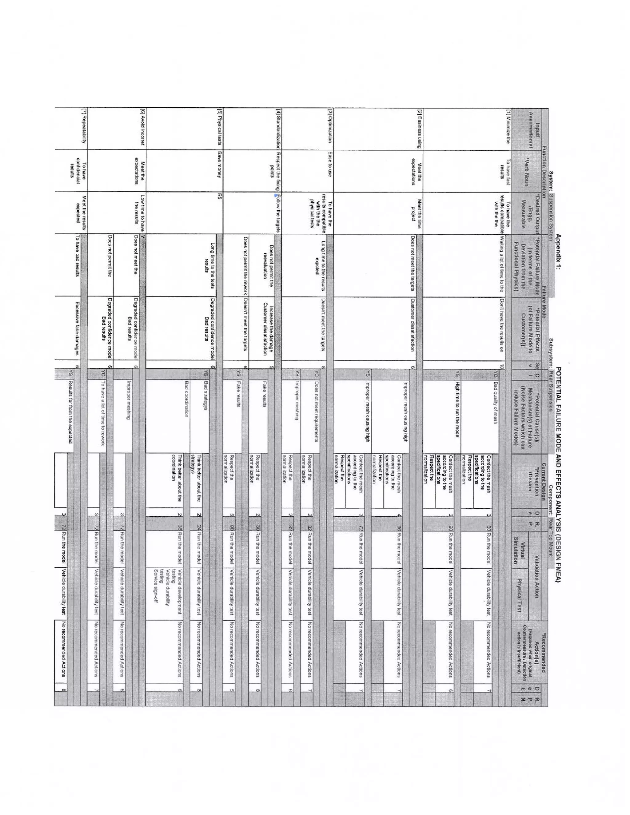
Note: see the dFmea on the appendix 1.
ROBUSTNESS TOOLS, ROBUSTNEES LINKAGES
Robustness Tools (Robustness Linkages) have been added to the FMEA process to significantly reduce
vehicle campaigns, enhance the corporate image, reduce warranty claims, and increase customer satisfaction.
These Robustness Tools primarily emanate from the P-Diagram, which identifies the five noise factors. These
factors need to be addressed early to make the design insensitive to the noise factors. This is the essence of
Robustness. It is the engineer's responsibility to ensure that the Robustness Tools are captured in the
engineering documentation.
BOUNDARY DIAGRAM
A boundary diagram is a graphical illustration of the relationships between the subsystems, assemblies,
subassemblies, and components within the object as well as the interfaces with the neighboring systems and
environments.
Boundary diagrams [5] [6] [7] [8] are a mandatory element of a Design FMEA. It breaks the FMEA into
manageable levels. When correctly constructed it provides detailed information to the Interface Matrix, P-
Diagram, and the FMEA. It is important to note that when completed or revised, the boundary diagram shall be
attached to the FMEA.
8. Page 8 of 11
Although boundary diagrams can be constructed to any level of detail, it is important to identify the
major elements, understand how they interact with each other, and how they may interact with outside systems.
Furthermore, early in the design program, a boundary diagram may be no more than a few blocks
representing major functions and their interrelationships at the system level. Then, as the design matures,
boundary diagrams may be revised, or additional ones developed to illustrate lower levels of detail, all the way
down to the component level.
For example, a completed system FMEA boundary diagram has blocks representing the subsystems
within its scope and its interfacing systems. Then, moving into the subsystem, another boundary diagram is
developed showing components of the subsystem as the block elements. In addition, on large systems a third or
fourth level boundary diagram may be necessary to fully identify smaller subsystems, components and their
relationships to the lowest level.
Figure 2 – Boundary conditions diagram.
INTERFACE MATRIX
A system interface matrix illustrates relationships between the subsystems, assemblies, subassemblies,
and components within the object as well as the interfaces with the neighboring systems and environments. A
system interface matrix documents the details, such as types of interfaces, strength/importance of interface,
potential effect of interface, and etc. It is a recommended robustness tool that acts as an input to Design FMEA
[4] [8]. It is important to note that not addressing interactions at this point can lead to potential warranty and
recall issues.
The information in a system interface matrix provides valuable input to Design FMEA [1] [2] [8], such
as primary functions or interface functions for system function identification, and/or the effects from
neighboring systems, environments or human for Potential Causes/Mechanisms Failure identification. Also, it
provides input to P-Diagram in the section of input/output and noise factors. In addition, every interface with
positive or negative impact should be verified. Then, negative impacts are analyzed for corrective and/or
preventive actions.
9. Page 9 of 11
Top mounting
Coil spring
Shock absorber
Rubber mounting
Clamping (nut)
Figure 3 – Interface matrix diagram.
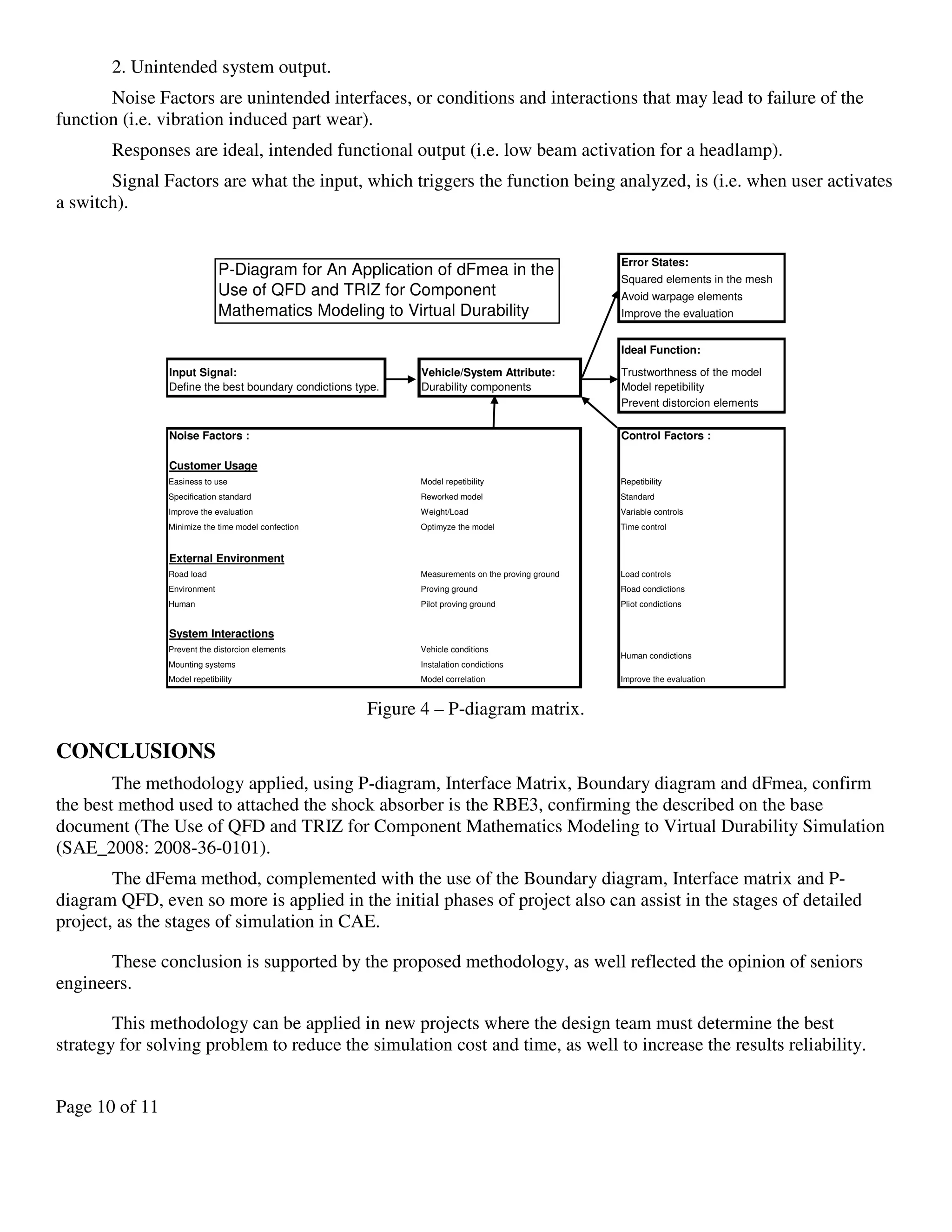
P-DIAGRAM
A P-Diagram [6] [7] [8] is a structured tool recommended to identify intended inputs (Signals) and
outputs (Functions) for the subject under investigation. Once these inputs and outputs are identified for a
specific Function, error states are identified. Noise factors, outside of the control of Design Engineers, that
could lead to the error states are then listed:
• Piece to Piece Variation
• Changes Over Time/Mileage (e.g. wear)
• Customer Usage
• External Environment (e.g. road type, weather)
• System Interactions
Finally, control factors are identified and means for Noise Factor Management settled to compensate for
the identified noise factors.
Depending on the level of detail contained in the P-Diagram, this information will input to various
FMEA columns. When completed or revised, it is recommended to attach the P-Diagram to the FMEA.
The P-Diagram [6] [7] [8] assists the engineers to:
• Describes noise factors, control factors, ideal function, and error states.
• Assists in the identification of Potential Causes for failure.
• Failure Modes Potential Effects of failure.
• Current Controls.
• Recommended Actions.
Control Factors are the means to make the items function more robust.
An Error State can be classified into two categories:
1. Deviation of intended Function - Deviation of intended Function is equal to Potential Failure Modes
in the FMEA. Potential Failure Modes are [1] [2] [3] [4] [5] [6] [7] [8]:
• No Function
• Partial Function (including Degraded Function over time)
• Intermittent Function
• Over Function
10. Page 10 of 11
2. Unintended system output.
Noise Factors are unintended interfaces, or conditions and interactions that may lead to failure of the
function (i.e. vibration induced part wear).
Responses are ideal, intended functional output (i.e. low beam activation for a headlamp).
Signal Factors are what the input, which triggers the function being analyzed, is (i.e. when user activates
a switch).
Error States:
Squared elements in the mesh
Avoid warpage elements
Improve the evaluation
Ideal Function:
Input Signal: Vehicle/System Attribute: Trustworthness of the model
Define the best boundary condictions type. Durability components Model repetibility
Prevent distorcion elements
Noise Factors : Control Factors :
Customer Usage
Easiness to use Model repetibility Repetibility
Specification standard Reworked model Standard
Improve the evaluation Weight/Load Variable controls
Minimize the time model confection Optimyze the model Time control
External Environment
Road load Measurements on the proving ground Load controls
Environment Proving ground Road condictions
Human Pilot proving ground Pliot condictions
System Interactions
Prevent the distorcion elements Vehicle conditions
Mounting systems Instalation condictions
Model repetibility Model correlation Improve the evaluation
Human condictions
P-Diagram for An Application of dFmea in the
Use of QFD and TRIZ for Component
Mathematics Modeling to Virtual Durability
Simulation.
Figure 4 – P-diagram matrix.
CONCLUSIONS
The methodology applied, using P-diagram, Interface Matrix, Boundary diagram and dFmea, confirm
the best method used to attached the shock absorber is the RBE3, confirming the described on the base
document (The Use of QFD and TRIZ for Component Mathematics Modeling to Virtual Durability Simulation
(SAE_2008: 2008-36-0101).
The dFema method, complemented with the use of the Boundary diagram, Interface matrix and P-
diagram QFD, even so more is applied in the initial phases of project also can assist in the stages of detailed
project, as the stages of simulation in CAE.
These conclusion is supported by the proposed methodology, as well reflected the opinion of seniors
engineers.
This methodology can be applied in new projects where the design team must determine the best
strategy for solving problem to reduce the simulation cost and time, as well to increase the results reliability.
11. Page 11 of 11
REFERENCES
[1] Palady, Paul, “ FMEA – Análise dos modos de falhas e seus efeitos”, editora Imam.
[2] Campos, José. “Risk Management And Fmea For Product Development”.
[3] Brussee, Warren / Mcgraw-hill Digital. “Statistics For Six Sigma Made Easy: Simplified Fmea”.
[4] ULLMAN, D. G. "The Mechanical Design Process". Singapore: McGraw-Hill Co., 1992.
[5] ANDRADE, R. S. (1991) Preliminary Evaluation of Needs in the Design Process, International Conference
on Engineering Design - ICED 91, Zurich, August, pp. 717-720.
[6] MADSEN, DAVID A. (1999) - "Geometric Dimensioning and Tolerancing", The Goodheart, Tinley Park -
Illinois USA.
[7] ASME Y14.5M STANDARD (1994) – Dimensioning and Tolerancing - The American Society of
Mechanical Engineering – 1994 (Revision of ANSI Y 14.5 M – 1982 (R1988).
[8] FORCELLINI, F.A, ROZENFELD, HENRIQYE – Gestão de Desenvolvimento de Produtos.
CONTACT INFORMATION
Silas Luis Sartori Paschoal da Silva Rosa
e-mail: silas.sartori@gmail.com
phone: +55 (71) 8166-7215
Iuri Pepe
e-mail: mpepe@ufba.br
phone: +55 (71) 3283-6619
APPENDIX