Downloaded 137 times
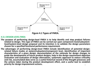

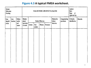
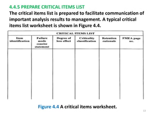
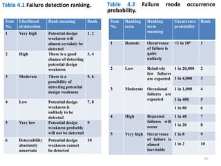
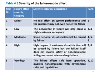
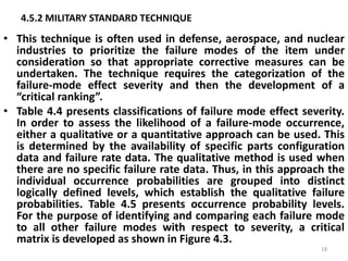
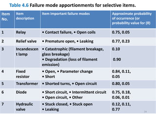
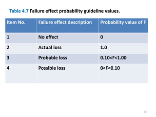

The document discusses failure modes and effects analysis (FMEA). It describes FMEA as a design tool used to analyze engineering systems by examining the effects of potential failure modes. The document outlines the types of FMEA (design-level, system-level, process-level), the steps to perform FMEA, and methods to assess failure criticality. Key terms used in FMEA are also defined.