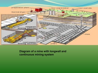
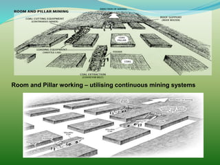
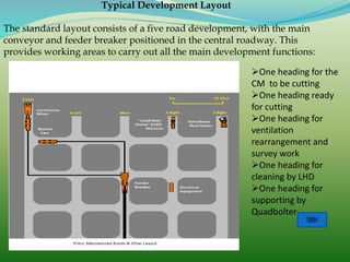
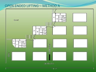
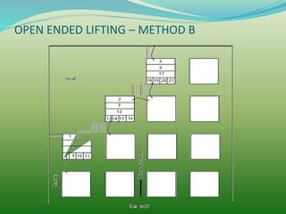
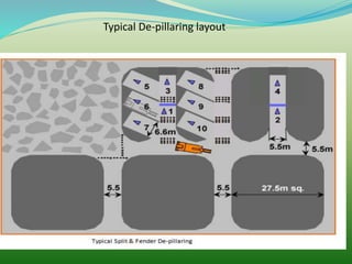
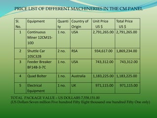
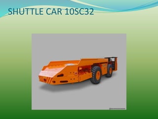
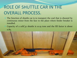
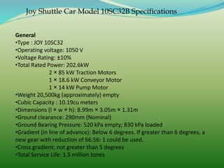
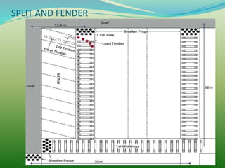
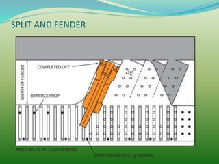
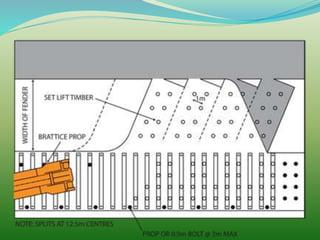
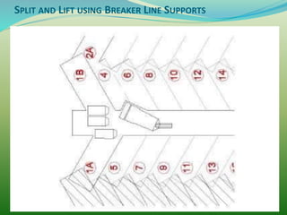
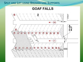
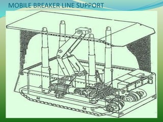
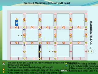
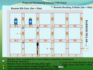
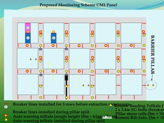
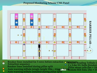
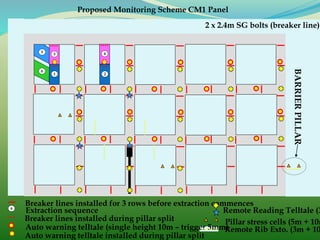
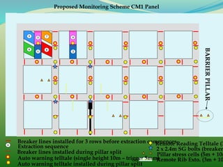
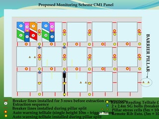
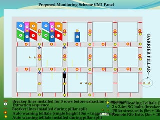
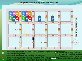
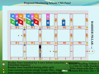
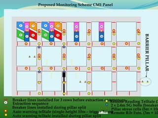
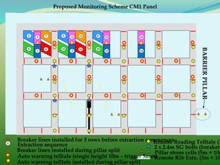
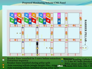
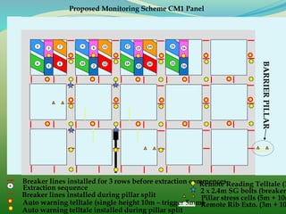
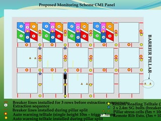
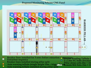
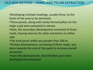
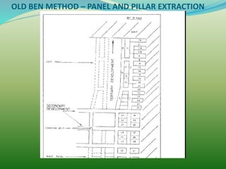
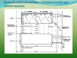
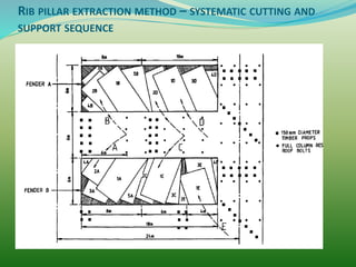
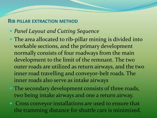
www.MINEPORTAL.in
ONLINE TEST SERIES FOR
GATE MINING
COAL/METAL FIRST/SECOND CLASS
COAL INDIA MT MINING EXAM
OVERMAN/SIRDAR EXAM
OTHER PSU MANAGEMENT TRAINEE EXAM
FREE STUDY MATERIAL/VIDEO LECTURES
ONLINE ORDER MINING BOOKS
CALL/WHATSAPP-8804777500 www.fb.com/mineportal.in
Diagram of a mine with longwall and
continuous mining system
Room and Pillar working – utilising continuous mining systems
FIRST WORKINGS
•First workings are conducted for two main reasons:
•To develop the pillars, bords and/or panels to
enable their subsequent extraction, and
•To develop multiple main entries for access to the
coal reserves. These entries are supported in the
long term by the pillars consequently formed.
FIRST WORKINGS
The number of development headings driven in any area of
workings can vary between two and eight.
This is dependent primarily on the purpose of development,
and the second method of working together with the following
factors:
• Mine capacity,
• Pillar and /or pillar and panel system relating to depth of
working, productivity and panel extraction system,
• Number of continuous miner units operating,
• Coal clearance system,
• Men and material transport, and
• Ventilation.
FIRST WORKINGS
Typical Development Layout
The standard layout consists of a five road development, with the main
conveyor and feeder breaker positioned in the central roadway. This
provides working areas to carry out all the main development functions:
One heading for the
CM to be cutting
One heading ready
for cutting
One heading for
ventilation
rearrangement and
survey work
One heading for
cleaning by LHD
One heading for
supporting by
Quadbolter
OPEN ENDED LIFTING – METHOD A
OPEN ENDED LIFTING – METHOD B
SPLIT AND FENDER
This is the most common method of pillar mining.
The pillars are usually square or rectangular with dimensions
dependent on the depth of working. Typically a pillar dimension of 45
x 45 meter is used at depth of around 450 m.
Basically the pillars developed by the first working are split into sub-
pillars and the fenders are then lifted (mined).
The width of the lift is governed by the length of the continuous miner,
roof conditions and support rules of the individual mine.
Generally the split is supported by roof bolts or other means of
supporting, depending on the timing of the mining.
Roof bolting and W-straps were supplemented with timber props and
bars.
SPLIT AND FENDER
The lifting operation took place usually towards the goaf side with
the pillar, with the basic philosophy of working adjacent to a
competent rib.
However, in mines with competent roof conditions, lifting from both
sides of the split was possible, and with the approval of mine
inspectorate.
When extracting on both left and right, pillars up to four meters in
width were left in the fenders to provide temporary support.
However, the current system of splitting with mobile breaker line
supports, lifting from both sides of the split is standard practice.
A small stook (support Buttress) of coal seam ( min width 2.0m) is
normally left to control caving, particularly on the goaf side.
Typical De-pillaring layout
PRICE LIST OF DIFFERENT MACHINERIES IN THE CM PANEL
Sl.
No.
Equipment Quanti
ty
Country of
Origin
Unit Price
US $
Total Price
US $
1 Continuous
Miner 12CM15-
10D
1 no. USA 2,791,265.00 2,791,265.00
2 Shuttle Car
10SC32B
2 no. RSA 934,617.00 1,869,234.00
3 Feeder Breaker
BF14B-3-7C
1 no. USA 743,312.00 743,312.00
4 Quad Bolter 1 no. Australia 1,183,225.00 1,183,225.00
5 Electrical
Equipment
1 no. UK 971,115.00 971,115.00
TOTAL PACKAGE VALUE – US DOLLARS 7,558,151.00
(US Dollars Seven million Five hundred Fifty Eight thousand one hundred Fifty One only)
SHUTTLE CAR 10SC32
ROLE OF SHUTTLE CAR IN THE
OVERALL PROCESS.
 The function of shuttle car is to transport the coal that is sheared by
continuous miner from the face to the place where feeder breaker is
installed.
 Capacity of a 10SC32 shuttle is 10.19 tons and the fill factor is about
0.85.
Joy Shuttle Car Model 10SC32B Specifications
General
•Type : JOY 10SC32
•Operating voltage: 1050 V
•Voltage Rating: ±10%
•Total Rated Power: 202.6kW
2 × 85 kW Traction Motors
1 × 18.6 kW Conveyor Motor
1 × 14 kW Pump Motor
•Weight 20,500kg (approximately) empty
•Cubic Capacity : 10.19cu meters
•Dimensions (l × w × h): 8.99m × 3.05m × 1.31m
•Ground clearance: 290mm (Nominal)
•Ground Bearing Pressure: 520 kPa empty; 830 kPa loaded
•Gradient (in line of advance): Below 6 degrees. If greater than 6 degrees, a
new gear with reduction of 66.56: 1 could be used.
•Cross gradient: not greater than 5 degrees
•Total Service Life: 1.5 million tones
SPLIT AND FENDER
SPLIT AND FENDER
SPLIT AND FENDER
SPLIT AND LIFT USING BREAKER LINE SUPPORTS
BREAKER LINE SUPPORT (BLS)
Advantages.
 Greater positive setting loads and roof support on goaf
edge .
 Cost saving in timber usage to defray their capital cost.
 Able to be reset to the new breaker line position as
extraction takes place faster than timber breaker lines can
be set.
 Increases potential continuous miner cutting time and
productivity.
 Through remote control they remove the active goaf edge
area personnel who would be required otherwise to set the
breaker-line props thus further improving safety.
MOBILE BREAKER LINE SUPPORT
Breaker lines installed for 3 rows before extraction commences6
Extraction sequence
Breaker lines installed during pillar split
Remote Reading Telltale (3
2 x 2.4m SG bolts (breaker
Pillar stress cells (5m + 10m
Auto warning telltale (single height 10m – trigger 5mm)Remote Rib Exto. (3m + 10
BARRIERPILLAR
Proposed Monitoring Scheme CM1 Panel
1
Auto warning telltale installed during pillar split
Breaker lines installed for 3 rows before extraction commences6
Extraction sequence
Breaker lines installed during pillar split
Remote Reading Telltale (3m + 10m)
2 x 2.4m SG bolts (breaker line)
Pillar stress cells (5m + 10m)
Auto warning telltale (single height 10m – trigger 5mm)
Remote Rib Exto. (3m + 10m)
BARRIERPILLAR
Proposed Monitoring Scheme CM1 Panel
1
Auto warning telltale installed during pillar split
2
Breaker lines installed for 3 rows before extraction commences6
Breaker lines installed during pillar split
Remote Reading Telltale (3
2 x 2.4m SG bolts (breaker
Pillar stress cells (5m + 10m
Auto warning telltale (single height 10m – trigger 5mm)Remote Rib Exto. (3m + 10
BARRIERPILLAR
Proposed Monitoring Scheme CM1 Panel
1
Auto warning telltale installed during pillar split
2
3
4
Breaker lines installed for 3 rows before extraction commences6
Extraction sequence
Breaker lines installed during pillar split
Remote Reading Telltale (3
2 x 2.4m SG bolts (breaker line)
Pillar stress cells (5m + 10m
Auto warning telltale (single height 10m – trigger 5mm)Remote Rib Exto. (3m + 10
BARRIERPILLAR
Proposed Monitoring Scheme CM1 Panel
1
Auto warning telltale installed during pillar split
2
3
5
6
4
Breaker lines installed for 3 rows before extraction commences6
Extraction sequence
Breaker lines installed during pillar split
Remote Reading Telltale (3
2 x 2.4m SG bolts (breaker
Pillar stress cells (5m + 10m
Auto warning telltale (single height 10m – trigger 5mm)Remote Rib Exto. (3m + 10
BARRIERPILLAR
Proposed Monitoring Scheme CM1 Panel
1
Auto warning telltale installed during pillar split
2
3
5
6
7
8
9
10
11
12
13
4
Breaker lines installed for 3 rows before extraction commences6
Extraction sequence
Breaker lines installed during pillar split
Remote Reading Telltale (3
2 x 2.4m SG bolts (breaker
Pillar stress cells (5m + 10m
Auto warning telltale (single height 10m – trigger 5mm)Remote Rib Exto. (3m + 10
BARRIERPILLAR
Proposed Monitoring Scheme CM1 Panel
1
Auto warning telltale installed during pillar split
2
3
5
6
7
8
9
10
11
12
13 14
154
Breaker lines installed for 3 rows before extraction commences6
Extraction sequence
Breaker lines installed during pillar split
Remote Reading Telltale (3
2 x 2.4m SG bolts (breaker
Pillar stress cells (5m + 10m
Auto warning telltale (single height 10m – trigger 5mm)Remote Rib Exto. (3m + 10
BARRIERPILLAR
Proposed Monitoring Scheme CM1 Panel
1
Auto warning telltale installed during pillar split
2
3
5
6
7
8
9
10
11
12
13 14
16154
Breaker lines installed for 3 rows before extraction commences6
Extraction sequence
Breaker lines installed during pillar split
Remote Reading Telltale (3
2 x 2.4m SG bolts (breaker
Pillar stress cells (5m + 10m
Auto warning telltale (single height 10m – trigger 5mm)Remote Rib Exto. (3m + 10
BARRIERPILLAR
Proposed Monitoring Scheme CM1 Panel
1
Auto warning telltale installed during pillar split
2
3
5
6
7
8
9
10
11
12
13 14
17
18
19
20
21
22
23
24
25
27
26
28
29
30
31
32
16154
Breaker lines installed for 3 rows before extraction commences6 Extraction sequence
Breaker lines installed during pillar split
Remote Reading Telltale (3m + 10m)
2 x 2.4m SG bolts (breaker line)
Pillar stress cells (5m + 10m)
Auto warning telltale (single height 10m – trigger 5mm)
Remote Rib Exto. (3m + 10m)
BARRIERPILLAR
Proposed Monitoring Scheme CM1 Panel
1
Auto warning telltale installed during pillar split
2
3
5
6
7
8
9
10
11
12
13 14
17
18
19
20
21
22
23
24
25
27
26
28
30
29
32
31
33
34
35
36
OLD BEN METHOD – PANEL AND PILLAR EXTRACTION
•Developing multiple headings, usually three, to the
limits of the area to be extracted.
•These panels, along with newly formed pillars (in the
virgin coal) were extracted in retreat.
•Here, the secondary development consisted of three
roads, leaving reserves for pillar extraction on either
side.
•The total panel width was greater than 200 m.
•Tertiary development, consisting of three roads, was
done towards the end of the panel to increase overall
extraction.
•From this development, short fenders were then
developed and extracted.
OLD BEN METHOD – PANEL AND PILLAR EXTRACTION
WONGAWILLI METHOD
 The Wongawilli system was developed at Wongawilli
Colliery in the southern coalfield of New South Wales in
the early 1960s.
 Generally with the Wongawilli system, a panel is created by
a secondary development consisting of three to five roads
and leaving a continuous pillar of coal between the
development and the previously caved area.
 The pillar is normally between 50 m and 150 m wide and is
extracted by developing and extracting 7 m wide ribs in a
modified split and lift system.
 The pillars formed by the development are extracted as the
rib extraction retreats. As a result of the length of the rib
pillars, this method resembles a shortwall face.
WONGAWILLI METHOD
 This method was developed to provide a single
working place to extract coal in a stress-relieved area
and to utilize the coal seam as support during
extraction.
 An overall extraction of 90 per cent was achieved by
this system.
WONGAWILLI METHOD
 The main disadvantages of the Wongawilli system
area:
 ➤ Excessive floor lift when splitting successive
headings in a large panel
 ➤ Difficulties when removing stooks on the return
run out of each heading
 ➤ Difficulties with ventilating rib pillar panels when
the roof caves completely, thus filling voids in the goaf
area and choking the ventilation flow.
 1. Provision of a single working place
2. Extraction of coal in stress relieved areas
3. Maximise extraction of the seam,
4. Simple system readily understood by all employees.
 The method provides;
a) A straight goaf line
b) Simple ventilation system, with air being coursed
via the goaf, and
c) Working within de-stressed areas.
WONGAWILLI METHOD
WONGAWILLI METHOD
RIB PILLAR EXTRACTION METHOD
RIB PILLAR EXTRACTION METHOD – SYSTEMATIC CUTTING AND
SUPPORT SEQUENCE
RIB PILLAR EXTRACTION METHOD – SYSTEMATIC CUTTING AND
SUPPORT SEQUENCE
RIB PILLAR EXTRACTION METHOD
 Panel Layout and Cutting Sequence
 The area allocated to rib-pillar mining is divided into
workable sections, and the primary development
normally consists of four roadways from the main
development to the limit of the remnant. The two
outer roads are utilized as return airways, and the two
inner road travelling and conveyor-belt roads. The
inner roads also serve as intake airways
 The secondary development consists of three roads,
two being intake airways and one a return airway.
 Cross conveyor installations are used to ensure that
the tramming distance for shuttle cars is minimized.

Development and depillaring with continuous miner

  • 1.
    www.MINEPORTAL.in ONLINE TEST SERIESFOR GATE MINING COAL/METAL FIRST/SECOND CLASS COAL INDIA MT MINING EXAM OVERMAN/SIRDAR EXAM OTHER PSU MANAGEMENT TRAINEE EXAM FREE STUDY MATERIAL/VIDEO LECTURES ONLINE ORDER MINING BOOKS CALL/WHATSAPP-8804777500 www.fb.com/mineportal.in
  • 3.
    Diagram of amine with longwall and continuous mining system
  • 4.
    Room and Pillarworking – utilising continuous mining systems
  • 5.
    FIRST WORKINGS •First workingsare conducted for two main reasons: •To develop the pillars, bords and/or panels to enable their subsequent extraction, and •To develop multiple main entries for access to the coal reserves. These entries are supported in the long term by the pillars consequently formed.
  • 6.
    FIRST WORKINGS The numberof development headings driven in any area of workings can vary between two and eight. This is dependent primarily on the purpose of development, and the second method of working together with the following factors: • Mine capacity, • Pillar and /or pillar and panel system relating to depth of working, productivity and panel extraction system, • Number of continuous miner units operating, • Coal clearance system, • Men and material transport, and • Ventilation.
  • 7.
  • 8.
    Typical Development Layout Thestandard layout consists of a five road development, with the main conveyor and feeder breaker positioned in the central roadway. This provides working areas to carry out all the main development functions: One heading for the CM to be cutting One heading ready for cutting One heading for ventilation rearrangement and survey work One heading for cleaning by LHD One heading for supporting by Quadbolter
  • 9.
    OPEN ENDED LIFTING– METHOD A
  • 10.
    OPEN ENDED LIFTING– METHOD B
  • 11.
    SPLIT AND FENDER Thisis the most common method of pillar mining. The pillars are usually square or rectangular with dimensions dependent on the depth of working. Typically a pillar dimension of 45 x 45 meter is used at depth of around 450 m. Basically the pillars developed by the first working are split into sub- pillars and the fenders are then lifted (mined). The width of the lift is governed by the length of the continuous miner, roof conditions and support rules of the individual mine. Generally the split is supported by roof bolts or other means of supporting, depending on the timing of the mining. Roof bolting and W-straps were supplemented with timber props and bars.
  • 12.
    SPLIT AND FENDER Thelifting operation took place usually towards the goaf side with the pillar, with the basic philosophy of working adjacent to a competent rib. However, in mines with competent roof conditions, lifting from both sides of the split was possible, and with the approval of mine inspectorate. When extracting on both left and right, pillars up to four meters in width were left in the fenders to provide temporary support. However, the current system of splitting with mobile breaker line supports, lifting from both sides of the split is standard practice. A small stook (support Buttress) of coal seam ( min width 2.0m) is normally left to control caving, particularly on the goaf side.
  • 13.
  • 14.
    PRICE LIST OFDIFFERENT MACHINERIES IN THE CM PANEL Sl. No. Equipment Quanti ty Country of Origin Unit Price US $ Total Price US $ 1 Continuous Miner 12CM15- 10D 1 no. USA 2,791,265.00 2,791,265.00 2 Shuttle Car 10SC32B 2 no. RSA 934,617.00 1,869,234.00 3 Feeder Breaker BF14B-3-7C 1 no. USA 743,312.00 743,312.00 4 Quad Bolter 1 no. Australia 1,183,225.00 1,183,225.00 5 Electrical Equipment 1 no. UK 971,115.00 971,115.00 TOTAL PACKAGE VALUE – US DOLLARS 7,558,151.00 (US Dollars Seven million Five hundred Fifty Eight thousand one hundred Fifty One only)
  • 15.
  • 16.
    ROLE OF SHUTTLECAR IN THE OVERALL PROCESS.  The function of shuttle car is to transport the coal that is sheared by continuous miner from the face to the place where feeder breaker is installed.  Capacity of a 10SC32 shuttle is 10.19 tons and the fill factor is about 0.85.
  • 17.
    Joy Shuttle CarModel 10SC32B Specifications General •Type : JOY 10SC32 •Operating voltage: 1050 V •Voltage Rating: ±10% •Total Rated Power: 202.6kW 2 × 85 kW Traction Motors 1 × 18.6 kW Conveyor Motor 1 × 14 kW Pump Motor •Weight 20,500kg (approximately) empty •Cubic Capacity : 10.19cu meters •Dimensions (l × w × h): 8.99m × 3.05m × 1.31m •Ground clearance: 290mm (Nominal) •Ground Bearing Pressure: 520 kPa empty; 830 kPa loaded •Gradient (in line of advance): Below 6 degrees. If greater than 6 degrees, a new gear with reduction of 66.56: 1 could be used. •Cross gradient: not greater than 5 degrees •Total Service Life: 1.5 million tones
  • 18.
  • 19.
  • 20.
  • 21.
    SPLIT AND LIFTUSING BREAKER LINE SUPPORTS
  • 22.
    SPLIT AND LIFTUSING BREAKER LINE SUPPORTS
  • 23.
    BREAKER LINE SUPPORT(BLS) Advantages.  Greater positive setting loads and roof support on goaf edge .  Cost saving in timber usage to defray their capital cost.  Able to be reset to the new breaker line position as extraction takes place faster than timber breaker lines can be set.  Increases potential continuous miner cutting time and productivity.  Through remote control they remove the active goaf edge area personnel who would be required otherwise to set the breaker-line props thus further improving safety.
  • 24.
  • 25.
    Breaker lines installedfor 3 rows before extraction commences6 Extraction sequence Breaker lines installed during pillar split Remote Reading Telltale (3 2 x 2.4m SG bolts (breaker Pillar stress cells (5m + 10m Auto warning telltale (single height 10m – trigger 5mm)Remote Rib Exto. (3m + 10 BARRIERPILLAR Proposed Monitoring Scheme CM1 Panel 1 Auto warning telltale installed during pillar split
  • 26.
    Breaker lines installedfor 3 rows before extraction commences6 Extraction sequence Breaker lines installed during pillar split Remote Reading Telltale (3m + 10m) 2 x 2.4m SG bolts (breaker line) Pillar stress cells (5m + 10m) Auto warning telltale (single height 10m – trigger 5mm) Remote Rib Exto. (3m + 10m) BARRIERPILLAR Proposed Monitoring Scheme CM1 Panel 1 Auto warning telltale installed during pillar split 2
  • 27.
    Breaker lines installedfor 3 rows before extraction commences6 Breaker lines installed during pillar split Remote Reading Telltale (3 2 x 2.4m SG bolts (breaker Pillar stress cells (5m + 10m Auto warning telltale (single height 10m – trigger 5mm)Remote Rib Exto. (3m + 10 BARRIERPILLAR Proposed Monitoring Scheme CM1 Panel 1 Auto warning telltale installed during pillar split 2 3
  • 28.
    4 Breaker lines installedfor 3 rows before extraction commences6 Extraction sequence Breaker lines installed during pillar split Remote Reading Telltale (3 2 x 2.4m SG bolts (breaker Pillar stress cells (5m + 10m Auto warning telltale (single height 10m – trigger 5mm)Remote Rib Exto. (3m + 10 BARRIERPILLAR Proposed Monitoring Scheme CM1 Panel 1 Auto warning telltale installed during pillar split 2 3
  • 29.
    4 Breaker lines installedfor 3 rows before extraction commences6 Extraction sequence Breaker lines installed during pillar split Remote Reading Telltale (3 2 x 2.4m SG bolts (breaker line) Pillar stress cells (5m + 10m Auto warning telltale (single height 10m – trigger 5mm)Remote Rib Exto. (3m + 10 BARRIERPILLAR Proposed Monitoring Scheme CM1 Panel 1 Auto warning telltale installed during pillar split 2 3 5 6
  • 30.
    4 Breaker lines installedfor 3 rows before extraction commences6 Extraction sequence Breaker lines installed during pillar split Remote Reading Telltale (3 2 x 2.4m SG bolts (breaker Pillar stress cells (5m + 10m Auto warning telltale (single height 10m – trigger 5mm)Remote Rib Exto. (3m + 10 BARRIERPILLAR Proposed Monitoring Scheme CM1 Panel 1 Auto warning telltale installed during pillar split 2 3 5 6 7 8
  • 31.
    4 Breaker lines installedfor 3 rows before extraction commences6 Extraction sequence Breaker lines installed during pillar split Remote Reading Telltale (3 2 x 2.4m SG bolts (breaker Pillar stress cells (5m + 10m Auto warning telltale (single height 10m – trigger 5mm)Remote Rib Exto. (3m + 10 BARRIERPILLAR Proposed Monitoring Scheme CM1 Panel 1 Auto warning telltale installed during pillar split 2 3 5 6 7 8 9 10
  • 32.
    4 Breaker lines installedfor 3 rows before extraction commences6 Extraction sequence Breaker lines installed during pillar split Remote Reading Telltale (3 2 x 2.4m SG bolts (breaker Pillar stress cells (5m + 10m Auto warning telltale (single height 10m – trigger 5mm)Remote Rib Exto. (3m + 10 BARRIERPILLAR Proposed Monitoring Scheme CM1 Panel 1 Auto warning telltale installed during pillar split 2 3 5 6 7 8 9 10 11 12 13
  • 33.
    4 Breaker lines installedfor 3 rows before extraction commences6 Extraction sequence Breaker lines installed during pillar split Remote Reading Telltale (3 2 x 2.4m SG bolts (breaker Pillar stress cells (5m + 10m Auto warning telltale (single height 10m – trigger 5mm)Remote Rib Exto. (3m + 10 BARRIERPILLAR Proposed Monitoring Scheme CM1 Panel 1 Auto warning telltale installed during pillar split 2 3 5 6 7 8 9 10 11 12 13 14
  • 34.
    154 Breaker lines installedfor 3 rows before extraction commences6 Extraction sequence Breaker lines installed during pillar split Remote Reading Telltale (3 2 x 2.4m SG bolts (breaker Pillar stress cells (5m + 10m Auto warning telltale (single height 10m – trigger 5mm)Remote Rib Exto. (3m + 10 BARRIERPILLAR Proposed Monitoring Scheme CM1 Panel 1 Auto warning telltale installed during pillar split 2 3 5 6 7 8 9 10 11 12 13 14
  • 35.
    16154 Breaker lines installedfor 3 rows before extraction commences6 Extraction sequence Breaker lines installed during pillar split Remote Reading Telltale (3 2 x 2.4m SG bolts (breaker Pillar stress cells (5m + 10m Auto warning telltale (single height 10m – trigger 5mm)Remote Rib Exto. (3m + 10 BARRIERPILLAR Proposed Monitoring Scheme CM1 Panel 1 Auto warning telltale installed during pillar split 2 3 5 6 7 8 9 10 11 12 13 14
  • 36.
    16154 Breaker lines installedfor 3 rows before extraction commences6 Extraction sequence Breaker lines installed during pillar split Remote Reading Telltale (3 2 x 2.4m SG bolts (breaker Pillar stress cells (5m + 10m Auto warning telltale (single height 10m – trigger 5mm)Remote Rib Exto. (3m + 10 BARRIERPILLAR Proposed Monitoring Scheme CM1 Panel 1 Auto warning telltale installed during pillar split 2 3 5 6 7 8 9 10 11 12 13 14 17 18
  • 37.
    16154 Breaker lines installedfor 3 rows before extraction commences6 Extraction sequence Breaker lines installed during pillar split Remote Reading Telltale (3 2 x 2.4m SG bolts (breaker Pillar stress cells (5m + 10m Auto warning telltale (single height 10m – trigger 5mm)Remote Rib Exto. (3m + 10 BARRIERPILLAR Proposed Monitoring Scheme CM1 Panel 1 Auto warning telltale installed during pillar split 2 3 5 6 7 8 9 10 11 12 13 14 17 18 19 20
  • 38.
    16154 Breaker lines installedfor 3 rows before extraction commences6 Extraction sequence Breaker lines installed during pillar split Remote Reading Telltale (3 2 x 2.4m SG bolts (breaker Pillar stress cells (5m + 10m Auto warning telltale (single height 10m – trigger 5mm)Remote Rib Exto. (3m + 10 BARRIERPILLAR Proposed Monitoring Scheme CM1 Panel 1 Auto warning telltale installed during pillar split 2 3 5 6 7 8 9 10 11 12 13 14 17 18 19 20 21 22
  • 39.
    16154 Breaker lines installedfor 3 rows before extraction commences6 Extraction sequence Breaker lines installed during pillar split Remote Reading Telltale (3 2 x 2.4m SG bolts (breaker Pillar stress cells (5m + 10m Auto warning telltale (single height 10m – trigger 5mm)Remote Rib Exto. (3m + 10 BARRIERPILLAR Proposed Monitoring Scheme CM1 Panel 1 Auto warning telltale installed during pillar split 2 3 5 6 7 8 9 10 11 12 13 14 17 18 19 20 21 22 23 24
  • 40.
    16154 Breaker lines installedfor 3 rows before extraction commences6 Extraction sequence Breaker lines installed during pillar split Remote Reading Telltale (3 2 x 2.4m SG bolts (breaker Pillar stress cells (5m + 10m Auto warning telltale (single height 10m – trigger 5mm)Remote Rib Exto. (3m + 10 BARRIERPILLAR Proposed Monitoring Scheme CM1 Panel 1 Auto warning telltale installed during pillar split 2 3 5 6 7 8 9 10 11 12 13 14 17 18 19 20 21 22 23 24 25 27 26 28
  • 41.
    16154 Breaker lines installedfor 3 rows before extraction commences6 Extraction sequence Breaker lines installed during pillar split Remote Reading Telltale (3 2 x 2.4m SG bolts (breaker Pillar stress cells (5m + 10m Auto warning telltale (single height 10m – trigger 5mm)Remote Rib Exto. (3m + 10 BARRIERPILLAR Proposed Monitoring Scheme CM1 Panel 1 Auto warning telltale installed during pillar split 2 3 5 6 7 8 9 10 11 12 13 14 17 18 19 20 21 22 23 24 25 27 26 28 29 30 31 32
  • 42.
    16154 Breaker lines installedfor 3 rows before extraction commences6 Extraction sequence Breaker lines installed during pillar split Remote Reading Telltale (3m + 10m) 2 x 2.4m SG bolts (breaker line) Pillar stress cells (5m + 10m) Auto warning telltale (single height 10m – trigger 5mm) Remote Rib Exto. (3m + 10m) BARRIERPILLAR Proposed Monitoring Scheme CM1 Panel 1 Auto warning telltale installed during pillar split 2 3 5 6 7 8 9 10 11 12 13 14 17 18 19 20 21 22 23 24 25 27 26 28 30 29 32 31 33 34 35 36
  • 43.
    OLD BEN METHOD– PANEL AND PILLAR EXTRACTION •Developing multiple headings, usually three, to the limits of the area to be extracted. •These panels, along with newly formed pillars (in the virgin coal) were extracted in retreat. •Here, the secondary development consisted of three roads, leaving reserves for pillar extraction on either side. •The total panel width was greater than 200 m. •Tertiary development, consisting of three roads, was done towards the end of the panel to increase overall extraction. •From this development, short fenders were then developed and extracted.
  • 44.
    OLD BEN METHOD– PANEL AND PILLAR EXTRACTION
  • 45.
    OLD BEN METHOD– PANEL AND PILLAR EXTRACTION
  • 46.
    WONGAWILLI METHOD  TheWongawilli system was developed at Wongawilli Colliery in the southern coalfield of New South Wales in the early 1960s.  Generally with the Wongawilli system, a panel is created by a secondary development consisting of three to five roads and leaving a continuous pillar of coal between the development and the previously caved area.  The pillar is normally between 50 m and 150 m wide and is extracted by developing and extracting 7 m wide ribs in a modified split and lift system.  The pillars formed by the development are extracted as the rib extraction retreats. As a result of the length of the rib pillars, this method resembles a shortwall face.
  • 47.
    WONGAWILLI METHOD  Thismethod was developed to provide a single working place to extract coal in a stress-relieved area and to utilize the coal seam as support during extraction.  An overall extraction of 90 per cent was achieved by this system.
  • 48.
    WONGAWILLI METHOD  Themain disadvantages of the Wongawilli system area:  ➤ Excessive floor lift when splitting successive headings in a large panel  ➤ Difficulties when removing stooks on the return run out of each heading  ➤ Difficulties with ventilating rib pillar panels when the roof caves completely, thus filling voids in the goaf area and choking the ventilation flow.
  • 49.
     1. Provisionof a single working place 2. Extraction of coal in stress relieved areas 3. Maximise extraction of the seam, 4. Simple system readily understood by all employees.  The method provides; a) A straight goaf line b) Simple ventilation system, with air being coursed via the goaf, and c) Working within de-stressed areas. WONGAWILLI METHOD
  • 50.
  • 51.
  • 52.
  • 53.
    RIB PILLAR EXTRACTIONMETHOD – SYSTEMATIC CUTTING AND SUPPORT SEQUENCE
  • 54.
    RIB PILLAR EXTRACTIONMETHOD – SYSTEMATIC CUTTING AND SUPPORT SEQUENCE
  • 55.
    RIB PILLAR EXTRACTIONMETHOD  Panel Layout and Cutting Sequence  The area allocated to rib-pillar mining is divided into workable sections, and the primary development normally consists of four roadways from the main development to the limit of the remnant. The two outer roads are utilized as return airways, and the two inner road travelling and conveyor-belt roads. The inner roads also serve as intake airways  The secondary development consists of three roads, two being intake airways and one a return airway.  Cross conveyor installations are used to ensure that the tramming distance for shuttle cars is minimized.