Downloaded 278 times

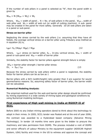
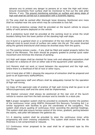
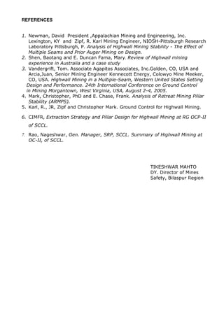
![Design of Web pillar
Strength of Web Pillar
Numerous empirical formulas are available to predict coal pillar strength, but Mark-
Bieniawski formula for rectangular pillar is best suitable Web and Barrier pillar
design.
Bieniawski formula for square pillar design is;
SP = SI[ 0.64 + 0.36 W / h ] (1
Where:
Sp= strength of Square pillar
SI = in situ coal strength = 6.0 for US condition and > 6.0 for Indian condition.
W = width of square pillar, and h = mining height
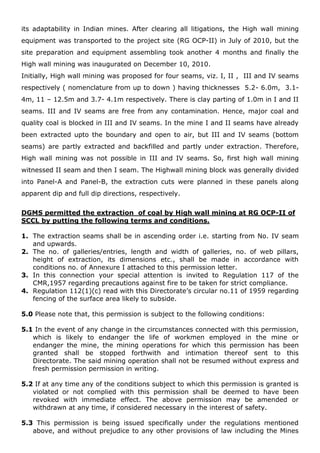
Later Mark modified this formula to design the rectangular pillar, which is known as
Mark- Bieniawski formula. The Mark-Bieniawski formula applies best for web pillars,
which are very long, narrow rectangular pillars. By far, the most widely accepted
formula for web pillars design in the United States today is the Mark-Bieniawski pillar
design formula.
Mark- Bieniawski formula for rectangular pillar is;
SP = SI [0.64 + 0.54 W / h – 0.18 W2
/Lh] (2
Where:
Sp= web or barrier pillar strength
SI = in situ coal strength
W = web or barrier pillar width, h = mining height, and
L = length of the pillar.
t
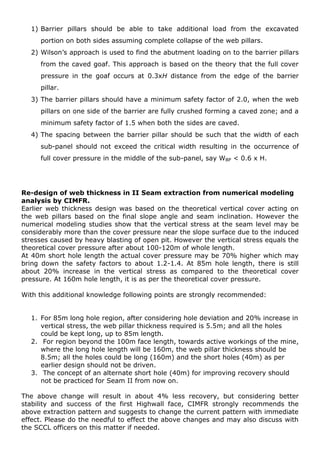
Front view of Highwall mining face
HIGHWALL BENCHES
Web Cuts Web Pillars](https://image.slidesharecdn.com/highwallmininganewapproachinindia-140608100610-phpapp01/85/Highwall-mining-a-new-approach-in-india-8-320.jpg)
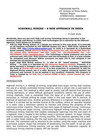
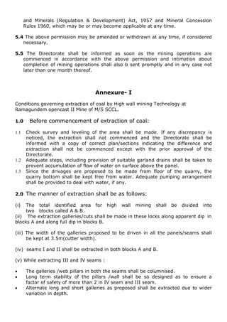
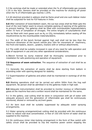
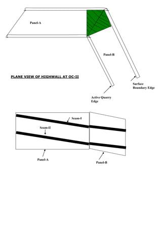
![In the case of high wall mining where the pillar length (miner penetration) is much
greater than either the pillar height or width, the last term may be omitted, and
Mark- Bieniawski formula (2) reduces to;
SP = SI [0.64 + 0.54 W / h] (3
In situ coal strength is normally taken as 6.2 MPa (900 psi, not for Indian Coal Mines).
For Indian Coal Mines, it is more than 20 MPa.
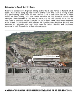
In India first high wall mining Technology was applied at RG OCP-II of SCCL and
completed successfully with little problem of roof collapses. Ground control layout
was formulated by CIMFR, Dhanbad. Web pillars strength was designed by using the
CIMFR`S formula, which is as follows.
Sp =0.27pc* h-0.36
+ (H/250 +1)(We/h -1) Mpa………………………………….(5)
Where, Sp = strength of web pillar (in Mpa)
Pc = compressive strength of sample of 25mm cube (23.8 Mpa);
h = height of extraction (in meter);
H = depth of cover(in meter) , and
We = equivalent width of web pillar (in meter)
= 4A/P
= 2W1*W2/W1+W2 (for rectangular pillar )
= 2W1 (W1+W2 ≈ W2 ,for long narrow web pillar of high wall)
Where, W1 is the width of web pillar
Stress on web pillar
Once web pillar strength is determined, an estimate of pillar loading is required to
calculate a safety factor. Pillar loading is estimated using tributary area load theory
as follows:
LP= SV(W + WE)(L)/W*L
Or, LP= SV(W + WE)/W ----------------------------------------(6
Where,
Lp = average vertical load on the pillar](https://image.slidesharecdn.com/highwallmininganewapproachinindia-140608100610-phpapp01/85/Highwall-mining-a-new-approach-in-india-9-320.jpg)
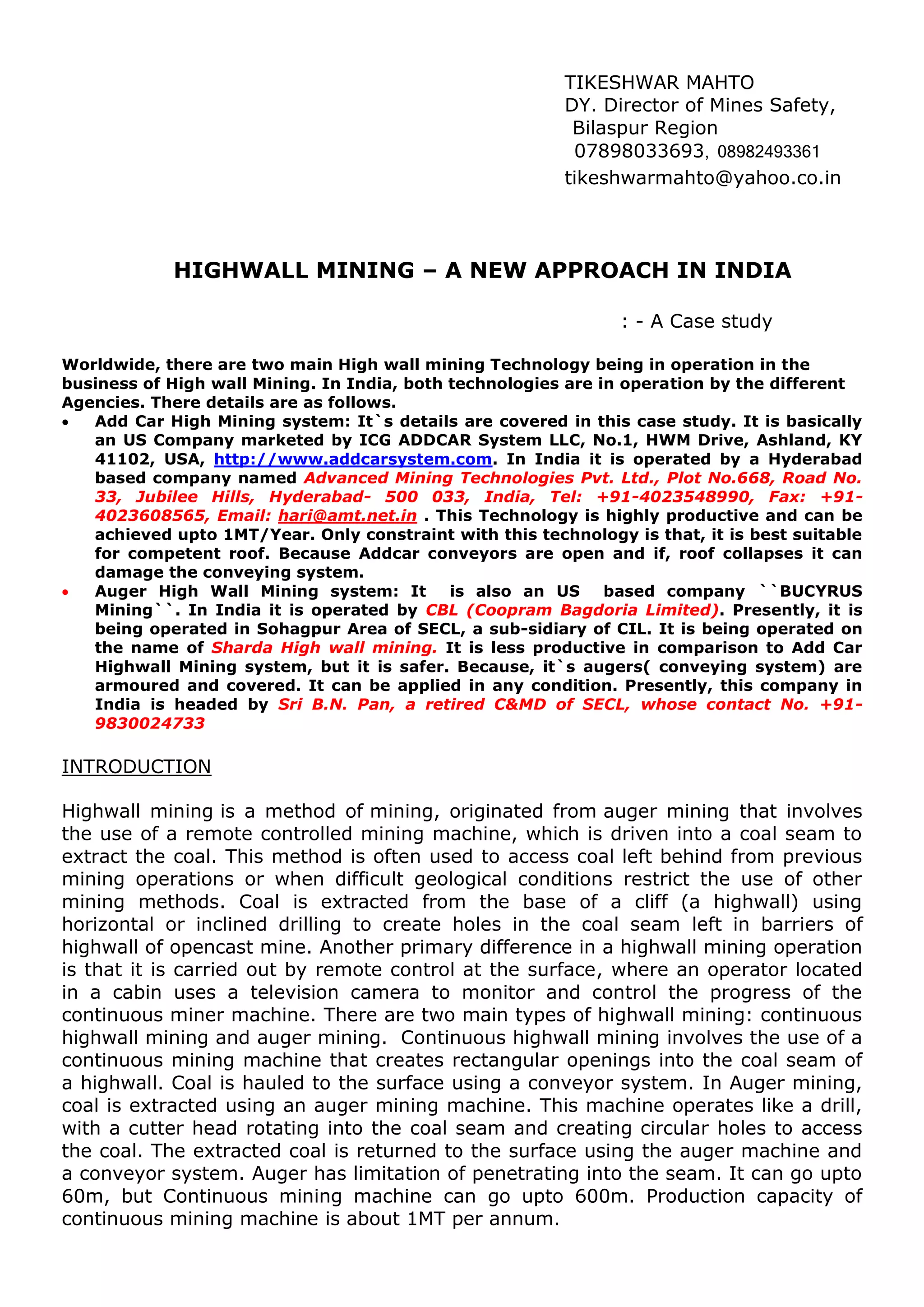
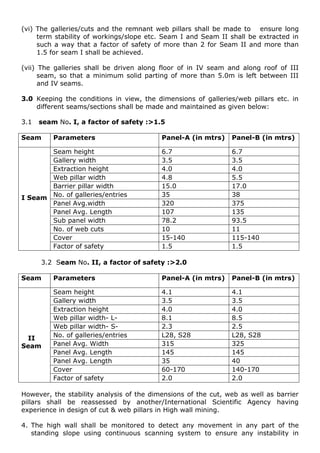
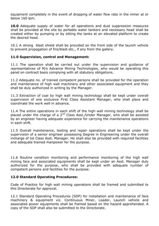
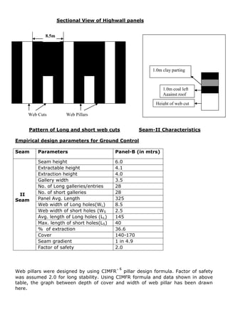
![SV = in situ vertical stress W
= web pillar width, WE = entry width (or web cut width) and L= length of web cut
The high wall mining equipment dictates the hole width, which varies from 2.7 to 3.6
m. In situ vertical stress depends on the overlying rock density and overburden
depth. Vertical stress gradient is typically 0.025 MPa/m. Overburden depth may be
taken as the average of maximum overburden depth and minimum overburden
depth on a high wall mining web pillar. 75% weightage is given to the maximum
overburden depth and 25% weightage to the minimum overburden depth, which is
as follows,
H = 0.75 * HMAX+ 0.25 * HMIN (7
Where:
HMAX = maximum overburden depth,
HMIN = minimum overburden depth, and
H= average depth of cover
And In-situ vertical stress,
SV = density of rock * overburden depth
Or, SV = 2.5 * H , t/m2
= 0.025 * H, Mpa
Hence, LP = SV(W + WE)/W
or, LP = 0.025 H (W + WE)/W Mpa
Finally, the safety factor of web pillar is calculated as:
SF = SP/LP (9
For design purposes, the stability factor for web pillars typically ranges from 1.3 to
2.0. CIMFR designed the FOS of web pillar of high wall mining at RGOCP-II in the
range of 1.5 to 2.0. FOS of 1.5 for top most seam (I-seam) , and 2.0 for lower
seams (II, IIIA, III and IV- seams)
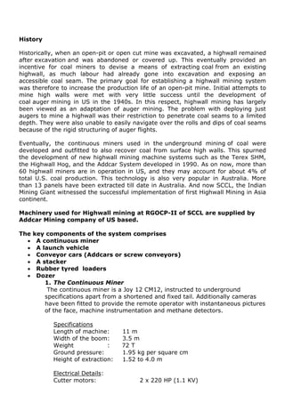
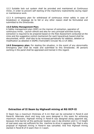
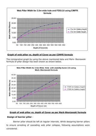
Design of barrier pillar
Strength of barrier pillar
Strength of barrier pillar can be calculated by using `Mark- Bieniawski formula or
CIMFR formula.
Mark- Bieniawski formula is;
SBP = SI [0.64 + 0.54 WBP / h] (10
Where, SBP = strength of barrier pillar, SI = In-situ coal strength= 6.0 for US
condition and > 6.0 for Indian condition, WBP = width of barrier pillar and h= height
of barrier pillar.](https://image.slidesharecdn.com/highwallmininganewapproachinindia-140608100610-phpapp01/85/Highwall-mining-a-new-approach-in-india-10-320.jpg)
The document presents an overview of highwall mining technology in India, detailing two major systems: the Addcar high mining system and the auger high wall mining system. It describes the operational capabilities, safety features, machinery used, and limitations of each system, emphasizing the importance of effective ground control and web pillar design to prevent collapses. The document highlights the first successful implementation of highwall mining technology in Asia at the SCCL's RG OCP-II site, showcasing its potential to enhance coal production from highwalls.