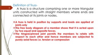
1) A truss is a structure composed of straight members connected at joints that allows the members to only experience axial forces from the connections and any applied loads.
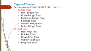
2) Trusses are divided into bridge trusses and roof trusses with various types of each including Pratt, Howe, Warren, and more.
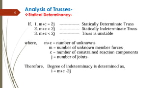
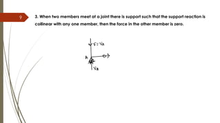
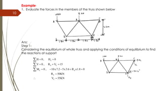
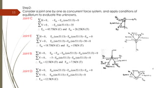
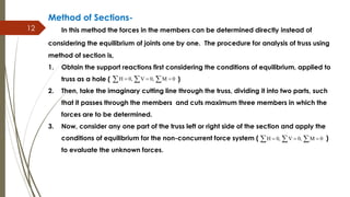
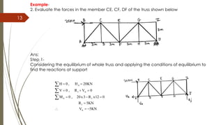
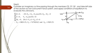
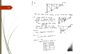
3) Trusses can be analyzed through the method of joints which involves applying equilibrium conditions to each joint sequentially or the method of sections which uses equilibrium on a cut portion of the truss to directly find member forces.