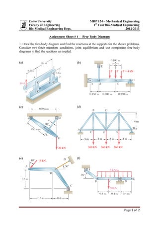
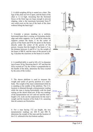
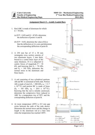
SlideShare a Scribd company logo
Page 1 of 2
Cairo University MDP 124 – Mechanical Engineering
Faculty of Engineering 1st
Year Bio-Medical Engineering
Bio-Medical Engineering Dept. 2012-2013
Assignment Sheet # 1 – Free-Body Diagram
1. Draw the free-body diagram and find the reactions at the supports for the shown problems.
Consider two-force members conditions, joint equilibrium and use component free-body
diagrams to find the reactions as needed.
360 kN 360 kN 360 kN
4 m
3 m 3 m 3 m 3 m
(c)
(b)(a)
(d)
20 kN
P = 4 kNP P
16 kN
(e) (f)
Page 2 of 2
2. A child weighing 40 kg is seated on a chair. The
legs of the chair are 0.4 m apart, and the back of the
chair is 1.2 m high. Assuming that the frictional
forces at the front legs are large enough to prevent
slipping, what is the maximum horizontal force F
one could exert on the top of the back of the chair
without lifting the back legs?
3. Consider a person standing on a uniform,
horizontal beam that is resting on frictionless knife-
edge and roller supports. Let A and B be where the
supports contact the beam, C be the center of
gravity of the beam and D be the point on the beam
directly under the center of the gravity of the
person. Assume that the length of the beam is 5 m,
the distance between A and D is 3 m, the weight of
the beam is 900 N, and the mass of the person is 60
kg. Calculate the reactions on the beam at A and B.
4. A modified dolly is used to lift a 0.2 m diameter
log of mass 36 kg. Knowing that θ= 45º and that the
force exerted at C by the worker is perpendicular to
the handle of the dolly, determine the force exerted
by the arms of the worker.
5. The shown platform is used to measure the
weight and center of gravity position of a man’s
body. The weight of the man is determined while he
is standing at the middle of the platform. The C.G.
location is obtained through a dynamometer reading
while the man is laying horizontally with his head
resting on the shown head rest. If the two readings
of the dynamometer are wt1 and wt2 and the man’s
height is H, work out the expressions for the man’s
weight and the location of his body C.G. assuming
that all contacts are frictionless.
6. For a man having 172 cm height, the two
dynamometer readings are 420 N and 490 N,
determine the weight of the man and the location of
his C.G. referred to his feet bottom surface.
Page 1 of 1
Cairo University MDP 124 – Mechanical Engineering
Faculty of Engineering 1st
Year Bio-Medical Engineering
Bio-Medical Engineering Dept. 2012-2013
Assignment Sheet # 2 – Internal Reactions Diagrams
1. Draw the internal reaction diagrams for the beams shown below:
(a) (b)
(c) (d)
2. Draw the internal reaction diagrams for the beams shown below:
(P = 150 N, wn = 2.5N/mm, Mb = 1000 N.mm, L = 1000 mm, x = 0.25)
Page 1 of 2
Cairo University MDP 124 – Mechanical Engineering
Faculty of Engineering 1st
Year Bio-Medical Engineering
Bio-Medical Engineering Dept. 2012-2013
Assignment Sheet # 3 – Axially Loaded Bars
1. Rod ABC is made of aluminum for which
E = 70 GPa.
(a) If P = 6 kN and Q = 42 kN, determine
the deflection of points A and B.
(b) If P = 4 kN, determine the value of Q so
that the deflection at A is zero and determine
the corresponding deflection of point B.
2. A 250 mm bar of 15 x 30 mm
rectangular cross section consists of
two aluminum layers, 5 mm thick,
brazed to a center brass layer of the
same thickness. If it is subjected to
centric forces of magnitude P = 30
kN, and knowing that Ea = 70 GPa
and Eb = 105 GPa, determine the
normal stress in the aluminum and
brass layers.
3. A rod consisting of two cylindrical portions
AB and BC is restrained at both ends. Portion
AB is made of steel (Es = 200 GPa, s = 11.7
x 10-6
/o
C) and portion BC is made of brass
(Eb = 105 GPa, b = 20.9 x 10⁻⁶
/o
C).
Knowing that the rod is initially unstressed,
determine the compressive force induced in
ABC by a temperature rise of 50o
C and the
corresponding deflection of point B.
4. At room temperature (20o
C) a 0.5 mm gap
exists between the ends of the rods shown.
Determine the normal stress and the change in
length in the aluminum rod at a later time
when the temperature has reached 140o
C.
Page 2 of 2
5. The 4-mm-diameter cable BC is made of a steel
with E = 200 GPa. Knowing that the maximum
stress in the cable must not exceed 190 MPa and
that the elongation of the cable must not exceed 6
mm, find the maximum load P that can be applied
as shown.
6. The steel frame (E = 200 GPa) shown has a
diagonal brace BD with a cross-sectional area of
1920 mm2
. Determine the largest allowable load P
if the change in length of member BD is not to
exceed 1.6 mm.
7. Link BD is made of brass (E = 105 GPa) and has a
cross-sectional area of 240 mm2
. Link CE is made
of aluminum (E = 72 GPa) and has a cross-
sectional area of 300 mm2
. Knowing that they
support rigid member ABC, determine the
maximum force P that can be applied vertically at
point A if the deflection of A is not to exceed 0.35
mm.
8. Rod AB is made of steel for which the yield
strength is Y = 450 MPa and E = 200 GPa. Rod
BC is made of an aluminum alloy for which Y =
280 MPa and E = 73 GPa. Determine the
maximum strain energy that can be acquired by the
composite rod ABC without causing any
permanent deformations.
Cairo University MDP 124 – Mechanical Engineering
Faculty of Engineering 1st
Year Bio-Medical Engineering
Bio-Medical Engineering Dept. 2012-2013
Assignment Sheet # 4 - Bending of Bars
1. For the shown sections, determine the
location of the centriodal line and hence
give expressions to calculate Izz , Iyy for each
section. For each section two types of strips
are used in construction. Strip(1) is having
width (W) and thickness (t1) while strip(2) is
of a height (H) and thickness (t2). Give
numerical values for these sections if
W=100 mm, t1=10 mm, H= 200 mm, and
t2=5 mm.
Strip(2)
Strip(1)
y
z
2. A wooden shelf 1000 mm long is used to
support a set of books as shown. The shelf
width is 200 mm while its thickness is 15
mm. The weight of the books is assumed to
be distributed force with intensity of 3
N/mm. Obtain the location of the critical
section and hence determine the maximum
and minimum stress for the proposed two
arrangements. 600 mm
1000 mm
Arrangement (2)
200 mm
Arrangement (1)
Simple support
3. ABC is an elastic beam which is kept in
position through the shown circular tie bar
BD. If a load P of 20 kN is applied at point
A obtain the value and direction of reactions
at supports C and D. Also get the stress and
strains in the tie rod BD. Draw the internal
reaction diagrams for the beam ABC and the
max. and min. stresses at the critical
section. Draw a sketch for the stress
distribution at this section. Obtain the
displacement of point A in direction of the
applied force P.
(H=200 mm, W= 40 mm, d = 20 mm, E =
210 GPa,  = 0.30 )
1000mm
1000 mm
C
D
m
m
500
B
P
A
Sec. m-m

40
200
4. The shown bar is subjected to a force F=
125 kN where the bar section is made of one
of the shown assemblies. Determine the
maximum and minimum stresses acting on
each of these sections. Locate the neutral
line for each section and draw the stress
distribution. For section assemblies, strip (1)
has a width of W=100 mm and a thickness
of t1=10 mm and for strip (2), the height is
H= 200 mm, and thickness is t2=5 mm.
Obtain the displacement of the applied force
if material elastic constant is E= 75 GPa.
FF
L
Strip(2)
Strip(1)
F
F
Force Action
Cairo University MDP 124 – Mechanical Engineering
Faculty of Engineering 1st
Year Bio-Medical Engineering
Bio-Medical Engineering Dept. 2012-2013
Assignment Sheet # 5 - Torsion of Bars
1- A 25 mm diameter shaft runs at 1200 rpm and transmits 30 kW. Calculate the
maximum shear stress and give the angle of twist in degrees if its length is 3 meters.
If a hole of 18 mm is dilled along the shaft length, what will be the maximum stress
and what will be the angle of twist for the hollow shaft if it is transmitting the same
power at the same speed. (G= 85.5 GPa.).
2- A hollow steel shaft is 30 mm outside diameter and 20 mm inside diameter. Calculate
the maximum transmitted power if the shaft is rotated at 1500 rpm and its material
can stand maximum shear stress of 70 MPa. If this shaft is replaced by another solid
one, determine its outer diameter if it is used to transmit the same power at the same
speed and is made of the same material. Compare between the resulting angles of
twist for the two shafts if each is of 750 mm length. (E= 210 GPa.,  = 0.30).
3- A solid shaft is used to transmit 7.5 kW at 2000 rpm. If the shaft is not to twist more
than 1o
on a length of 12 times its diameter and its maximum shear stress is not to
exceed 45 MPa., Determine the minimum shaft diameter. (G = 73 GPa).
4- Two steel shafts are assembled as shown. The hollow shaft is of 50 mm outer
diameter and 35 mm inner diameter. The solid shaft is 35 mm and is welded to the
inner surface of the hollow one. Obtain the maximum allowed power transmitted by
this assembly if the maximum shear stress does not exceed 60 MPa., and both are
rotated at 2500 rpm. What will be the total angle of twist for this compound shaft.
(G= 81 GPa., L= 300 mm.).
300 mm 300 mm
80 mm Solid Shaft
Cairo University MDP 124 – Mechanical Engineering
Faculty of Engineering 1st
Year Bio-Medical Engineering
Bio-Medical Engineering Dept. 2012-2013
Assignment Sheet # 6 - Thin Walled Pressure Containers
1-The tank of the air compressor is
subjected to an internal pressure of 0.63
MPa. If the internal diameter of the tank
is 550 mm, and the wall thickness is 6
mm, determine the stress components
acting at point A.
2-A water tank is filled to the top as
shown. The tank has a wall thickness of
20 mm at the lower section and a
diameter of 10 m. Determine the hoop
stress at the base of the tank. (The mass
density of the water = 1000 Kg/m³.)
3-A scuba diver's tank is made of
ASTM-A242 steel. The ends are
hemispherical with wall thickness of 3
mm. and diameter of 0.3 m. based on a
factor of safety against yielding of 4.0;
determine the largest internal pressure
that the tank can hold. ( 350 MPa)
4-The open-ended polyvinyl chloride
pipe has an inner diameter of 100 mm
and thickness of 5 mm. if it carries
flowing water at 0.42 MPa pressure,
determine the state of stress in the walls
of the pipe. If the flow of water within
the pipe is stopped due to the closing of
a valve, determine the state of stress in
the walls of the pipe. Neglect the weight
of the water. Assume the supports only
exert vertical forces on the pipe.
5-A spherical gas tank has an inner
radius of r=1.5 m. if it’s subjected to an
internal pressure of p=300 KPa,
determine its required thickness if the
maximum normal stress is not to exceed
12 MPa.
6-The thin walled cylinder can be
supported in of two ways as shown.
Determine the state of stress in the wall
of the cylinder for both cases if the
piston P causes the internal pressure to
be 0.3 Mpa. The wall thickness is 6 mm.
7-Air pressure in the cylinder is
increased by exerting forces P=2 KN on
the two pistons, each having a radius of
45 mm. if the cylinder has a wall
thickness of 2 mm, determine the state
of stress in the wall of the cylinder.
8-The cap on the cylindrical tank is
bolted to the tank along the flanges. The
tank has an inner diameter of 1.5 m and
a wall thickness of 18 mm. if the largest
normal stress is not to exceed 150 MPa,
determine the maximum pressure the
tank can sustain. Also, compute the
number of bolts required to attach the
cap to the tank if each bolt has a
diameter of 20 mm. the allowable stress
for the bolts is 180 MPa.
Cairo University MDP 124 – Mechanical Engineering
Faculty of Engineering 1st
Year Bio-Medical Engineering
Bio-Medical Engineering Dept. 2012-2013
Sheet 7 - Stress Transformation
1. For the following loads acting on a bar having 50 mm diameter and 1000 mm length , sketch
the stress element and draw Mohr’s circle for stress and determine the values and directions of
principal stresses and maximum shear stresses:
a) Axial load of 235 kN.
b) Axial load of 235 kN with pressure on the bar surface of 600 bar.
c) Bending moment of 1.2 kN.m and a torque of 1.0 kN.m.
d) All the above given loads.
2. A shaft having diameter of d subjected to bending moment Mb and torsional moment of T,
prove that the maximum normal stress and the maximum shear stress are given by the following
expressions:















2
3max 11
16
b
b
M
T
d
M

 ,
2
3max 1
16







b
b
M
T
d
M


Check these relations using values and results of problem (1-c)
3. A closed thin walled pressure container having mean diameter D, thickness t and length L is
subjected to internal pressure p. Derive the expressions for the maximum normal stress and
maximum shear stress.
4. The shown thin walled steel container is used
to keep gas under pressure of 30 bar. The
container’s diameter is 200 mm and its totallength
is 700 mm. If the allowable normal stress for the
used steel weld is 100 MPa., determine the
required wall thickness and give the values of the
stresses developed in the weld lines. If an inclined
weld line, which makes an angle of 15o
with the
cylinder’s axis, .replaces the axial one, what will
be the values of normal and tangential stresses
acting on this inclined weld line
Weld Lines
Spherical Head
5. Strain gauges are applied to the surface of a
circular bar having diameter of 50 mm subjected
to an axial force of 235 kN and torsional moment
of 1.2 kN.m. If the setting of the of the strain
gauges are at 45o
to the bar axis as shown.
Determine the strain readings of both gauges. (E =
210 GPa.,  =0.33)
mm
Strain Gauges
T
structure problems

More Related Content

What's hot

Steel design-examples
Steel design-examplesSteel design-examples
Steel design-examples
Faisal Amin
 
Simple Stress: Normal Stress
Simple Stress: Normal StressSimple Stress: Normal Stress
Simple Stress: Normal Stress
Lk Rigor
 
Chapter 6-structural-analysis-8th-edition-solution
Chapter 6-structural-analysis-8th-edition-solutionChapter 6-structural-analysis-8th-edition-solution
Chapter 6-structural-analysis-8th-edition-solution
Daniel Nunes
 
structural analysis CE engg. solved ex.
structural analysis CE engg. solved ex.structural analysis CE engg. solved ex.
structural analysis CE engg. solved ex.
IMALONE1
 
Chapter 6
Chapter 6Chapter 6
Chapter 6
Neagal Shu
 
Bending stress
Bending stressBending stress
Bending stress
Taral Soliya
 
First moment of area
First moment of areaFirst moment of area
First moment of area
Salman Jailani
 
Chapter 15
Chapter 15Chapter 15
Chapter 15
aryaanuj1
 
Structural Analysis 8th Edition Solutions Manual
Structural Analysis 8th Edition Solutions ManualStructural Analysis 8th Edition Solutions Manual
Structural Analysis 8th Edition Solutions Manual
Bahzad5
 
Earthquake Load Calculation (base shear method)
Earthquake Load Calculation (base shear method)Earthquake Load Calculation (base shear method)
Earthquake Load Calculation (base shear method)
Shekh Muhsen Uddin Ahmed
 
Hibbeler chapter5
Hibbeler chapter5Hibbeler chapter5
Hibbeler chapter5laiba javed
 
Lecture 12 deflection in beams
Lecture 12 deflection in beamsLecture 12 deflection in beams
Lecture 12 deflection in beamsDeepak Agarwal
 
Stresses in beams
Stresses in beamsStresses in beams
Stresses in beams
SURYAKANT KUMAR
 
Ch06 07 pure bending & transverse shear
Ch06 07 pure bending & transverse shearCh06 07 pure bending & transverse shear
Ch06 07 pure bending & transverse shear
Dario Ch
 
Flexural design of beam...PRC-I
Flexural design of beam...PRC-IFlexural design of beam...PRC-I
Flexural design of beam...PRC-I
Irfan Malik
 
Ref F2F Week 4 - Solution_unlocked.pdf
Ref F2F Week 4 - Solution_unlocked.pdfRef F2F Week 4 - Solution_unlocked.pdf
Ref F2F Week 4 - Solution_unlocked.pdf
Robin Arthur Flores
 
Solution Manul for Structural Analysis in SI Units 10th Edition by Russell Hi...
Solution Manul for Structural Analysis in SI Units 10th Edition by Russell Hi...Solution Manul for Structural Analysis in SI Units 10th Edition by Russell Hi...
Solution Manul for Structural Analysis in SI Units 10th Edition by Russell Hi...
physicsbook
 
Hibbeler chapter10
Hibbeler chapter10Hibbeler chapter10
Hibbeler chapter10ahmedalnamer
 

What's hot (20)

Steel design-examples
Steel design-examplesSteel design-examples
Steel design-examples
 
Simple Stress: Normal Stress
Simple Stress: Normal StressSimple Stress: Normal Stress
Simple Stress: Normal Stress
 
Chapter 6-structural-analysis-8th-edition-solution
Chapter 6-structural-analysis-8th-edition-solutionChapter 6-structural-analysis-8th-edition-solution
Chapter 6-structural-analysis-8th-edition-solution
 
01 01 chapgere[1]
01 01 chapgere[1]01 01 chapgere[1]
01 01 chapgere[1]
 
structural analysis CE engg. solved ex.
structural analysis CE engg. solved ex.structural analysis CE engg. solved ex.
structural analysis CE engg. solved ex.
 
Chapter 6
Chapter 6Chapter 6
Chapter 6
 
6 shearing stresses
6 shearing stresses6 shearing stresses
6 shearing stresses
 
Bending stress
Bending stressBending stress
Bending stress
 
First moment of area
First moment of areaFirst moment of area
First moment of area
 
Chapter 15
Chapter 15Chapter 15
Chapter 15
 
Structural Analysis 8th Edition Solutions Manual
Structural Analysis 8th Edition Solutions ManualStructural Analysis 8th Edition Solutions Manual
Structural Analysis 8th Edition Solutions Manual
 
Earthquake Load Calculation (base shear method)
Earthquake Load Calculation (base shear method)Earthquake Load Calculation (base shear method)
Earthquake Load Calculation (base shear method)
 
Hibbeler chapter5
Hibbeler chapter5Hibbeler chapter5
Hibbeler chapter5
 
Lecture 12 deflection in beams
Lecture 12 deflection in beamsLecture 12 deflection in beams
Lecture 12 deflection in beams
 
Stresses in beams
Stresses in beamsStresses in beams
Stresses in beams
 
Ch06 07 pure bending & transverse shear
Ch06 07 pure bending & transverse shearCh06 07 pure bending & transverse shear
Ch06 07 pure bending & transverse shear
 
Flexural design of beam...PRC-I
Flexural design of beam...PRC-IFlexural design of beam...PRC-I
Flexural design of beam...PRC-I
 
Ref F2F Week 4 - Solution_unlocked.pdf
Ref F2F Week 4 - Solution_unlocked.pdfRef F2F Week 4 - Solution_unlocked.pdf
Ref F2F Week 4 - Solution_unlocked.pdf
 
Solution Manul for Structural Analysis in SI Units 10th Edition by Russell Hi...
Solution Manul for Structural Analysis in SI Units 10th Edition by Russell Hi...Solution Manul for Structural Analysis in SI Units 10th Edition by Russell Hi...
Solution Manul for Structural Analysis in SI Units 10th Edition by Russell Hi...
 
Hibbeler chapter10
Hibbeler chapter10Hibbeler chapter10
Hibbeler chapter10
 

Similar to structure problems

CE 6306 STRENGTH OF MATERIALS
CE 6306 STRENGTH OF MATERIALSCE 6306 STRENGTH OF MATERIALS
CE 6306 STRENGTH OF MATERIALS
BIBIN CHIDAMBARANATHAN
 
Mechanics of Materials: Question Bank from old VTU Question papers
Mechanics of Materials: Question Bank from old VTU Question papersMechanics of Materials: Question Bank from old VTU Question papers
Mechanics of Materials: Question Bank from old VTU Question papers
Hareesha N Gowda, Dayananda Sagar College of Engg, Bangalore
 
Mechanics of solids 1 lecture-1
Mechanics of solids 1 lecture-1Mechanics of solids 1 lecture-1
Mechanics of solids 1 lecture-1
EngrKhalid Yousaf
 
Unit 2 simple stresses and strain
Unit 2 simple stresses and strainUnit 2 simple stresses and strain
Unit 2 simple stresses and strain
PratikAkarte2
 
Assignment 3
Assignment 3Assignment 3
Assignment 3
Yatin Singh
 
ME6503 design of machine elements - question bank.
ME6503 design of machine elements  - question bank.ME6503 design of machine elements  - question bank.
ME6503 design of machine elements - question bank.
Mohan2405
 
Assignment shear and bending
Assignment shear and bendingAssignment shear and bending
Assignment shear and bending
Yatin Singh
 
Simple stresses and Stain
Simple stresses and StainSimple stresses and Stain
Simple stresses and Stain
Hamood Saif
 
L1303017175
L1303017175L1303017175
L1303017175
IOSR Journals
 
Ce6306 strength of materials
Ce6306 strength of materialsCe6306 strength of materials
Ce6306 strength of materials
praveen kumar
 
Ce6306 strength of materials
Ce6306 strength of materialsCe6306 strength of materials
Ce6306 strength of materials
Siddhu Siddhu
 
1 lista 2020.2 res mat cart
1 lista 2020.2   res mat cart1 lista 2020.2   res mat cart
1 lista 2020.2 res mat cart
Eunice Santos
 
C09 m-403032016 som
C09 m-403032016 somC09 m-403032016 som
C09 m-403032016 som
vinodh kumar
 
Mm210(2)
Mm210(2)Mm210(2)
Mm210(2)
Osman Atalay
 
strength of materials TUTORIAL 1
strength of materials TUTORIAL 1strength of materials TUTORIAL 1
strength of materials TUTORIAL 1
musadoto
 
Strength of materials
Strength of materialsStrength of materials
Strength of materials
Reyam AL Mousawi
 
X10703 (me8593)
X10703 (me8593)X10703 (me8593)
X10703 (me8593)
BIBIN CHIDAMBARANATHAN
 
Strength of materials_I
Strength of materials_IStrength of materials_I
Strength of materials_I
Pralhad Kore
 
9 a01302 strength of materials i
9 a01302 strength of materials   i9 a01302 strength of materials   i
9 a01302 strength of materials i
Sree Murthy
 
design-of-combined-footings-by-is-456-ppt.pdf
design-of-combined-footings-by-is-456-ppt.pdfdesign-of-combined-footings-by-is-456-ppt.pdf
design-of-combined-footings-by-is-456-ppt.pdf
yohannesmesfin7
 

Similar to structure problems (20)

CE 6306 STRENGTH OF MATERIALS
CE 6306 STRENGTH OF MATERIALSCE 6306 STRENGTH OF MATERIALS
CE 6306 STRENGTH OF MATERIALS
 
Mechanics of Materials: Question Bank from old VTU Question papers
Mechanics of Materials: Question Bank from old VTU Question papersMechanics of Materials: Question Bank from old VTU Question papers
Mechanics of Materials: Question Bank from old VTU Question papers
 
Mechanics of solids 1 lecture-1
Mechanics of solids 1 lecture-1Mechanics of solids 1 lecture-1
Mechanics of solids 1 lecture-1
 
Unit 2 simple stresses and strain
Unit 2 simple stresses and strainUnit 2 simple stresses and strain
Unit 2 simple stresses and strain
 
Assignment 3
Assignment 3Assignment 3
Assignment 3
 
ME6503 design of machine elements - question bank.
ME6503 design of machine elements  - question bank.ME6503 design of machine elements  - question bank.
ME6503 design of machine elements - question bank.
 
Assignment shear and bending
Assignment shear and bendingAssignment shear and bending
Assignment shear and bending
 
Simple stresses and Stain
Simple stresses and StainSimple stresses and Stain
Simple stresses and Stain
 
L1303017175
L1303017175L1303017175
L1303017175
 
Ce6306 strength of materials
Ce6306 strength of materialsCe6306 strength of materials
Ce6306 strength of materials
 
Ce6306 strength of materials
Ce6306 strength of materialsCe6306 strength of materials
Ce6306 strength of materials
 
1 lista 2020.2 res mat cart
1 lista 2020.2   res mat cart1 lista 2020.2   res mat cart
1 lista 2020.2 res mat cart
 
C09 m-403032016 som
C09 m-403032016 somC09 m-403032016 som
C09 m-403032016 som
 
Mm210(2)
Mm210(2)Mm210(2)
Mm210(2)
 
strength of materials TUTORIAL 1
strength of materials TUTORIAL 1strength of materials TUTORIAL 1
strength of materials TUTORIAL 1
 
Strength of materials
Strength of materialsStrength of materials
Strength of materials
 
X10703 (me8593)
X10703 (me8593)X10703 (me8593)
X10703 (me8593)
 
Strength of materials_I
Strength of materials_IStrength of materials_I
Strength of materials_I
 
9 a01302 strength of materials i
9 a01302 strength of materials   i9 a01302 strength of materials   i
9 a01302 strength of materials i
 
design-of-combined-footings-by-is-456-ppt.pdf
design-of-combined-footings-by-is-456-ppt.pdfdesign-of-combined-footings-by-is-456-ppt.pdf
design-of-combined-footings-by-is-456-ppt.pdf
 

More from cairo university

Tocci chapter 13 applications of programmable logic devices extended
Tocci chapter 13 applications of programmable logic devices extendedTocci chapter 13 applications of programmable logic devices extended
Tocci chapter 13 applications of programmable logic devices extended
cairo university
 
Tocci chapter 12 memory devices
Tocci chapter 12 memory devicesTocci chapter 12 memory devices
Tocci chapter 12 memory devices
cairo university
 
Tocci ch 9 msi logic circuits
Tocci ch 9 msi logic circuitsTocci ch 9 msi logic circuits
Tocci ch 9 msi logic circuits
cairo university
 
Tocci ch 7 counters and registers modified x
Tocci ch 7 counters and registers modified xTocci ch 7 counters and registers modified x
Tocci ch 7 counters and registers modified x
cairo university
 
Tocci ch 6 digital arithmetic operations and circuits
Tocci ch 6 digital arithmetic operations and circuitsTocci ch 6 digital arithmetic operations and circuits
Tocci ch 6 digital arithmetic operations and circuits
cairo university
 
Tocci ch 3 5 boolean algebra, logic gates, combinational circuits, f fs, - re...
Tocci ch 3 5 boolean algebra, logic gates, combinational circuits, f fs, - re...Tocci ch 3 5 boolean algebra, logic gates, combinational circuits, f fs, - re...
Tocci ch 3 5 boolean algebra, logic gates, combinational circuits, f fs, - re...
cairo university
 
A15 sedra ch 15 memory circuits
A15  sedra ch 15 memory circuitsA15  sedra ch 15 memory circuits
A15 sedra ch 15 memory circuits
cairo university
 
A14 sedra ch 14 advanced mos and bipolar logic circuits
A14  sedra ch 14 advanced mos and bipolar logic circuitsA14  sedra ch 14 advanced mos and bipolar logic circuits
A14 sedra ch 14 advanced mos and bipolar logic circuits
cairo university
 
A13 sedra ch 13 cmos digital logic circuits
A13  sedra ch 13 cmos digital logic circuitsA13  sedra ch 13 cmos digital logic circuits
A13 sedra ch 13 cmos digital logic circuits
cairo university
 
A09 sedra ch 9 frequency response
A09  sedra ch 9 frequency responseA09  sedra ch 9 frequency response
A09 sedra ch 9 frequency response
cairo university
 
5 sedra ch 05 mosfet.ppsx
5  sedra ch 05  mosfet.ppsx5  sedra ch 05  mosfet.ppsx
5 sedra ch 05 mosfet.ppsx
cairo university
 
5 sedra ch 05 mosfet
5  sedra ch 05  mosfet5  sedra ch 05  mosfet
5 sedra ch 05 mosfet
cairo university
 
5 sedra ch 05 mosfet revision
5  sedra ch 05  mosfet revision5  sedra ch 05  mosfet revision
5 sedra ch 05 mosfet revision
cairo university
 
Fields Lec 2
Fields Lec 2Fields Lec 2
Fields Lec 2
cairo university
 
Fields Lec 1
Fields Lec 1Fields Lec 1
Fields Lec 1
cairo university
 
Fields Lec 5&6
Fields Lec 5&6Fields Lec 5&6
Fields Lec 5&6
cairo university
 
Fields Lec 4
Fields Lec 4Fields Lec 4
Fields Lec 4
cairo university
 
Fields Lec 3
Fields Lec 3Fields Lec 3
Fields Lec 3
cairo university
 
Lecture 2 (system overview of c8051 f020) rv01
Lecture 2 (system overview of c8051 f020) rv01Lecture 2 (system overview of c8051 f020) rv01
Lecture 2 (system overview of c8051 f020) rv01
cairo university
 
Lecture 1 (course overview and 8051 architecture) rv01
Lecture 1 (course overview and 8051 architecture) rv01Lecture 1 (course overview and 8051 architecture) rv01
Lecture 1 (course overview and 8051 architecture) rv01
cairo university
 

More from cairo university (20)

Tocci chapter 13 applications of programmable logic devices extended
Tocci chapter 13 applications of programmable logic devices extendedTocci chapter 13 applications of programmable logic devices extended
Tocci chapter 13 applications of programmable logic devices extended
 
Tocci chapter 12 memory devices
Tocci chapter 12 memory devicesTocci chapter 12 memory devices
Tocci chapter 12 memory devices
 
Tocci ch 9 msi logic circuits
Tocci ch 9 msi logic circuitsTocci ch 9 msi logic circuits
Tocci ch 9 msi logic circuits
 
Tocci ch 7 counters and registers modified x
Tocci ch 7 counters and registers modified xTocci ch 7 counters and registers modified x
Tocci ch 7 counters and registers modified x
 
Tocci ch 6 digital arithmetic operations and circuits
Tocci ch 6 digital arithmetic operations and circuitsTocci ch 6 digital arithmetic operations and circuits
Tocci ch 6 digital arithmetic operations and circuits
 
Tocci ch 3 5 boolean algebra, logic gates, combinational circuits, f fs, - re...
Tocci ch 3 5 boolean algebra, logic gates, combinational circuits, f fs, - re...Tocci ch 3 5 boolean algebra, logic gates, combinational circuits, f fs, - re...
Tocci ch 3 5 boolean algebra, logic gates, combinational circuits, f fs, - re...
 
A15 sedra ch 15 memory circuits
A15  sedra ch 15 memory circuitsA15  sedra ch 15 memory circuits
A15 sedra ch 15 memory circuits
 
A14 sedra ch 14 advanced mos and bipolar logic circuits
A14  sedra ch 14 advanced mos and bipolar logic circuitsA14  sedra ch 14 advanced mos and bipolar logic circuits
A14 sedra ch 14 advanced mos and bipolar logic circuits
 
A13 sedra ch 13 cmos digital logic circuits
A13  sedra ch 13 cmos digital logic circuitsA13  sedra ch 13 cmos digital logic circuits
A13 sedra ch 13 cmos digital logic circuits
 
A09 sedra ch 9 frequency response
A09  sedra ch 9 frequency responseA09  sedra ch 9 frequency response
A09 sedra ch 9 frequency response
 
5 sedra ch 05 mosfet.ppsx
5  sedra ch 05  mosfet.ppsx5  sedra ch 05  mosfet.ppsx
5 sedra ch 05 mosfet.ppsx
 
5 sedra ch 05 mosfet
5  sedra ch 05  mosfet5  sedra ch 05  mosfet
5 sedra ch 05 mosfet
 
5 sedra ch 05 mosfet revision
5  sedra ch 05  mosfet revision5  sedra ch 05  mosfet revision
5 sedra ch 05 mosfet revision
 
Fields Lec 2
Fields Lec 2Fields Lec 2
Fields Lec 2
 
Fields Lec 1
Fields Lec 1Fields Lec 1
Fields Lec 1
 
Fields Lec 5&6
Fields Lec 5&6Fields Lec 5&6
Fields Lec 5&6
 
Fields Lec 4
Fields Lec 4Fields Lec 4
Fields Lec 4
 
Fields Lec 3
Fields Lec 3Fields Lec 3
Fields Lec 3
 
Lecture 2 (system overview of c8051 f020) rv01
Lecture 2 (system overview of c8051 f020) rv01Lecture 2 (system overview of c8051 f020) rv01
Lecture 2 (system overview of c8051 f020) rv01
 
Lecture 1 (course overview and 8051 architecture) rv01
Lecture 1 (course overview and 8051 architecture) rv01Lecture 1 (course overview and 8051 architecture) rv01
Lecture 1 (course overview and 8051 architecture) rv01
 

Recently uploaded

Standard Reomte Control Interface - Neometrix
Standard Reomte Control Interface - NeometrixStandard Reomte Control Interface - Neometrix
Standard Reomte Control Interface - Neometrix
Neometrix_Engineering_Pvt_Ltd
 
CW RADAR, FMCW RADAR, FMCW ALTIMETER, AND THEIR PARAMETERS
CW RADAR, FMCW RADAR, FMCW ALTIMETER, AND THEIR PARAMETERSCW RADAR, FMCW RADAR, FMCW ALTIMETER, AND THEIR PARAMETERS
CW RADAR, FMCW RADAR, FMCW ALTIMETER, AND THEIR PARAMETERS
veerababupersonal22
 
Recycled Concrete Aggregate in Construction Part III
Recycled Concrete Aggregate in Construction Part IIIRecycled Concrete Aggregate in Construction Part III
Recycled Concrete Aggregate in Construction Part III
Aditya Rajan Patra
 
Forklift Classes Overview by Intella Parts
Forklift Classes Overview by Intella PartsForklift Classes Overview by Intella Parts
Forklift Classes Overview by Intella Parts
Intella Parts
 
Hierarchical Digital Twin of a Naval Power System
Hierarchical Digital Twin of a Naval Power SystemHierarchical Digital Twin of a Naval Power System
Hierarchical Digital Twin of a Naval Power System
Kerry Sado
 
AP LAB PPT.pdf ap lab ppt no title specific
AP LAB PPT.pdf ap lab ppt no title specificAP LAB PPT.pdf ap lab ppt no title specific
AP LAB PPT.pdf ap lab ppt no title specific
BrazilAccount1
 
block diagram and signal flow graph representation
block diagram and signal flow graph representationblock diagram and signal flow graph representation
block diagram and signal flow graph representation
Divya Somashekar
 
NUMERICAL SIMULATIONS OF HEAT AND MASS TRANSFER IN CONDENSING HEAT EXCHANGERS...
NUMERICAL SIMULATIONS OF HEAT AND MASS TRANSFER IN CONDENSING HEAT EXCHANGERS...NUMERICAL SIMULATIONS OF HEAT AND MASS TRANSFER IN CONDENSING HEAT EXCHANGERS...
NUMERICAL SIMULATIONS OF HEAT AND MASS TRANSFER IN CONDENSING HEAT EXCHANGERS...
ssuser7dcef0
 
Design and Analysis of Algorithms-DP,Backtracking,Graphs,B&B
Design and Analysis of Algorithms-DP,Backtracking,Graphs,B&BDesign and Analysis of Algorithms-DP,Backtracking,Graphs,B&B
Design and Analysis of Algorithms-DP,Backtracking,Graphs,B&B
Sreedhar Chowdam
 
Student information management system project report ii.pdf
Student information management system project report ii.pdfStudent information management system project report ii.pdf
Student information management system project report ii.pdf
Kamal Acharya
 
space technology lecture notes on satellite
space technology lecture notes on satellitespace technology lecture notes on satellite
space technology lecture notes on satellite
ongomchris
 
Hybrid optimization of pumped hydro system and solar- Engr. Abdul-Azeez.pdf
Hybrid optimization of pumped hydro system and solar- Engr. Abdul-Azeez.pdfHybrid optimization of pumped hydro system and solar- Engr. Abdul-Azeez.pdf
Hybrid optimization of pumped hydro system and solar- Engr. Abdul-Azeez.pdf
fxintegritypublishin
 
HYDROPOWER - Hydroelectric power generation
HYDROPOWER - Hydroelectric power generationHYDROPOWER - Hydroelectric power generation
HYDROPOWER - Hydroelectric power generation
Robbie Edward Sayers
 
Sachpazis:Terzaghi Bearing Capacity Estimation in simple terms with Calculati...
Sachpazis:Terzaghi Bearing Capacity Estimation in simple terms with Calculati...Sachpazis:Terzaghi Bearing Capacity Estimation in simple terms with Calculati...
Sachpazis:Terzaghi Bearing Capacity Estimation in simple terms with Calculati...
Dr.Costas Sachpazis
 
CME397 Surface Engineering- Professional Elective
CME397 Surface Engineering- Professional ElectiveCME397 Surface Engineering- Professional Elective
CME397 Surface Engineering- Professional Elective
karthi keyan
 
Cosmetic shop management system project report.pdf
Cosmetic shop management system project report.pdfCosmetic shop management system project report.pdf
Cosmetic shop management system project report.pdf
Kamal Acharya
 
Immunizing Image Classifiers Against Localized Adversary Attacks
Immunizing Image Classifiers Against Localized Adversary AttacksImmunizing Image Classifiers Against Localized Adversary Attacks
Immunizing Image Classifiers Against Localized Adversary Attacks
gerogepatton
 
weather web application report.pdf
weather web application report.pdfweather web application report.pdf
weather web application report.pdf
Pratik Pawar
 
一比一原版(UofT毕业证)多伦多大学毕业证成绩单如何办理
一比一原版(UofT毕业证)多伦多大学毕业证成绩单如何办理一比一原版(UofT毕业证)多伦多大学毕业证成绩单如何办理
一比一原版(UofT毕业证)多伦多大学毕业证成绩单如何办理
ydteq
 
Gen AI Study Jams _ For the GDSC Leads in India.pdf
Gen AI Study Jams _ For the GDSC Leads in India.pdfGen AI Study Jams _ For the GDSC Leads in India.pdf
Gen AI Study Jams _ For the GDSC Leads in India.pdf
gdsczhcet
 

Recently uploaded (20)

Standard Reomte Control Interface - Neometrix
Standard Reomte Control Interface - NeometrixStandard Reomte Control Interface - Neometrix
Standard Reomte Control Interface - Neometrix
 
CW RADAR, FMCW RADAR, FMCW ALTIMETER, AND THEIR PARAMETERS
CW RADAR, FMCW RADAR, FMCW ALTIMETER, AND THEIR PARAMETERSCW RADAR, FMCW RADAR, FMCW ALTIMETER, AND THEIR PARAMETERS
CW RADAR, FMCW RADAR, FMCW ALTIMETER, AND THEIR PARAMETERS
 
Recycled Concrete Aggregate in Construction Part III
Recycled Concrete Aggregate in Construction Part IIIRecycled Concrete Aggregate in Construction Part III
Recycled Concrete Aggregate in Construction Part III
 
Forklift Classes Overview by Intella Parts
Forklift Classes Overview by Intella PartsForklift Classes Overview by Intella Parts
Forklift Classes Overview by Intella Parts
 
Hierarchical Digital Twin of a Naval Power System
Hierarchical Digital Twin of a Naval Power SystemHierarchical Digital Twin of a Naval Power System
Hierarchical Digital Twin of a Naval Power System
 
AP LAB PPT.pdf ap lab ppt no title specific
AP LAB PPT.pdf ap lab ppt no title specificAP LAB PPT.pdf ap lab ppt no title specific
AP LAB PPT.pdf ap lab ppt no title specific
 
block diagram and signal flow graph representation
block diagram and signal flow graph representationblock diagram and signal flow graph representation
block diagram and signal flow graph representation
 
NUMERICAL SIMULATIONS OF HEAT AND MASS TRANSFER IN CONDENSING HEAT EXCHANGERS...
NUMERICAL SIMULATIONS OF HEAT AND MASS TRANSFER IN CONDENSING HEAT EXCHANGERS...NUMERICAL SIMULATIONS OF HEAT AND MASS TRANSFER IN CONDENSING HEAT EXCHANGERS...
NUMERICAL SIMULATIONS OF HEAT AND MASS TRANSFER IN CONDENSING HEAT EXCHANGERS...
 
Design and Analysis of Algorithms-DP,Backtracking,Graphs,B&B
Design and Analysis of Algorithms-DP,Backtracking,Graphs,B&BDesign and Analysis of Algorithms-DP,Backtracking,Graphs,B&B
Design and Analysis of Algorithms-DP,Backtracking,Graphs,B&B
 
Student information management system project report ii.pdf
Student information management system project report ii.pdfStudent information management system project report ii.pdf
Student information management system project report ii.pdf
 
space technology lecture notes on satellite
space technology lecture notes on satellitespace technology lecture notes on satellite
space technology lecture notes on satellite
 
Hybrid optimization of pumped hydro system and solar- Engr. Abdul-Azeez.pdf
Hybrid optimization of pumped hydro system and solar- Engr. Abdul-Azeez.pdfHybrid optimization of pumped hydro system and solar- Engr. Abdul-Azeez.pdf
Hybrid optimization of pumped hydro system and solar- Engr. Abdul-Azeez.pdf
 
HYDROPOWER - Hydroelectric power generation
HYDROPOWER - Hydroelectric power generationHYDROPOWER - Hydroelectric power generation
HYDROPOWER - Hydroelectric power generation
 
Sachpazis:Terzaghi Bearing Capacity Estimation in simple terms with Calculati...
Sachpazis:Terzaghi Bearing Capacity Estimation in simple terms with Calculati...Sachpazis:Terzaghi Bearing Capacity Estimation in simple terms with Calculati...
Sachpazis:Terzaghi Bearing Capacity Estimation in simple terms with Calculati...
 
CME397 Surface Engineering- Professional Elective
CME397 Surface Engineering- Professional ElectiveCME397 Surface Engineering- Professional Elective
CME397 Surface Engineering- Professional Elective
 
Cosmetic shop management system project report.pdf
Cosmetic shop management system project report.pdfCosmetic shop management system project report.pdf
Cosmetic shop management system project report.pdf
 
Immunizing Image Classifiers Against Localized Adversary Attacks
Immunizing Image Classifiers Against Localized Adversary AttacksImmunizing Image Classifiers Against Localized Adversary Attacks
Immunizing Image Classifiers Against Localized Adversary Attacks
 
weather web application report.pdf
weather web application report.pdfweather web application report.pdf
weather web application report.pdf
 
一比一原版(UofT毕业证)多伦多大学毕业证成绩单如何办理
一比一原版(UofT毕业证)多伦多大学毕业证成绩单如何办理一比一原版(UofT毕业证)多伦多大学毕业证成绩单如何办理
一比一原版(UofT毕业证)多伦多大学毕业证成绩单如何办理
 
Gen AI Study Jams _ For the GDSC Leads in India.pdf
Gen AI Study Jams _ For the GDSC Leads in India.pdfGen AI Study Jams _ For the GDSC Leads in India.pdf
Gen AI Study Jams _ For the GDSC Leads in India.pdf
 

structure problems

  • 1. Page 1 of 2 Cairo University MDP 124 – Mechanical Engineering Faculty of Engineering 1st Year Bio-Medical Engineering Bio-Medical Engineering Dept. 2012-2013 Assignment Sheet # 1 – Free-Body Diagram 1. Draw the free-body diagram and find the reactions at the supports for the shown problems. Consider two-force members conditions, joint equilibrium and use component free-body diagrams to find the reactions as needed. 360 kN 360 kN 360 kN 4 m 3 m 3 m 3 m 3 m (c) (b)(a) (d) 20 kN P = 4 kNP P 16 kN (e) (f)
  • 2. Page 2 of 2 2. A child weighing 40 kg is seated on a chair. The legs of the chair are 0.4 m apart, and the back of the chair is 1.2 m high. Assuming that the frictional forces at the front legs are large enough to prevent slipping, what is the maximum horizontal force F one could exert on the top of the back of the chair without lifting the back legs? 3. Consider a person standing on a uniform, horizontal beam that is resting on frictionless knife- edge and roller supports. Let A and B be where the supports contact the beam, C be the center of gravity of the beam and D be the point on the beam directly under the center of the gravity of the person. Assume that the length of the beam is 5 m, the distance between A and D is 3 m, the weight of the beam is 900 N, and the mass of the person is 60 kg. Calculate the reactions on the beam at A and B. 4. A modified dolly is used to lift a 0.2 m diameter log of mass 36 kg. Knowing that θ= 45º and that the force exerted at C by the worker is perpendicular to the handle of the dolly, determine the force exerted by the arms of the worker. 5. The shown platform is used to measure the weight and center of gravity position of a man’s body. The weight of the man is determined while he is standing at the middle of the platform. The C.G. location is obtained through a dynamometer reading while the man is laying horizontally with his head resting on the shown head rest. If the two readings of the dynamometer are wt1 and wt2 and the man’s height is H, work out the expressions for the man’s weight and the location of his body C.G. assuming that all contacts are frictionless. 6. For a man having 172 cm height, the two dynamometer readings are 420 N and 490 N, determine the weight of the man and the location of his C.G. referred to his feet bottom surface.
  • 3. Page 1 of 1 Cairo University MDP 124 – Mechanical Engineering Faculty of Engineering 1st Year Bio-Medical Engineering Bio-Medical Engineering Dept. 2012-2013 Assignment Sheet # 2 – Internal Reactions Diagrams 1. Draw the internal reaction diagrams for the beams shown below: (a) (b) (c) (d) 2. Draw the internal reaction diagrams for the beams shown below: (P = 150 N, wn = 2.5N/mm, Mb = 1000 N.mm, L = 1000 mm, x = 0.25)
  • 4. Page 1 of 2 Cairo University MDP 124 – Mechanical Engineering Faculty of Engineering 1st Year Bio-Medical Engineering Bio-Medical Engineering Dept. 2012-2013 Assignment Sheet # 3 – Axially Loaded Bars 1. Rod ABC is made of aluminum for which E = 70 GPa. (a) If P = 6 kN and Q = 42 kN, determine the deflection of points A and B. (b) If P = 4 kN, determine the value of Q so that the deflection at A is zero and determine the corresponding deflection of point B. 2. A 250 mm bar of 15 x 30 mm rectangular cross section consists of two aluminum layers, 5 mm thick, brazed to a center brass layer of the same thickness. If it is subjected to centric forces of magnitude P = 30 kN, and knowing that Ea = 70 GPa and Eb = 105 GPa, determine the normal stress in the aluminum and brass layers. 3. A rod consisting of two cylindrical portions AB and BC is restrained at both ends. Portion AB is made of steel (Es = 200 GPa, s = 11.7 x 10⁻⁶ /o C) and portion BC is made of brass (Eb = 105 GPa, b = 20.9 x 10⁻⁶ /o C). Knowing that the rod is initially unstressed, determine the compressive force induced in ABC by a temperature rise of 50o C and the corresponding deflection of point B. 4. At room temperature (20o C) a 0.5 mm gap exists between the ends of the rods shown. Determine the normal stress and the change in length in the aluminum rod at a later time when the temperature has reached 140o C.
  • 5. Page 2 of 2 5. The 4-mm-diameter cable BC is made of a steel with E = 200 GPa. Knowing that the maximum stress in the cable must not exceed 190 MPa and that the elongation of the cable must not exceed 6 mm, find the maximum load P that can be applied as shown. 6. The steel frame (E = 200 GPa) shown has a diagonal brace BD with a cross-sectional area of 1920 mm2 . Determine the largest allowable load P if the change in length of member BD is not to exceed 1.6 mm. 7. Link BD is made of brass (E = 105 GPa) and has a cross-sectional area of 240 mm2 . Link CE is made of aluminum (E = 72 GPa) and has a cross- sectional area of 300 mm2 . Knowing that they support rigid member ABC, determine the maximum force P that can be applied vertically at point A if the deflection of A is not to exceed 0.35 mm. 8. Rod AB is made of steel for which the yield strength is Y = 450 MPa and E = 200 GPa. Rod BC is made of an aluminum alloy for which Y = 280 MPa and E = 73 GPa. Determine the maximum strain energy that can be acquired by the composite rod ABC without causing any permanent deformations.
  • 6. Cairo University MDP 124 – Mechanical Engineering Faculty of Engineering 1st Year Bio-Medical Engineering Bio-Medical Engineering Dept. 2012-2013 Assignment Sheet # 4 - Bending of Bars 1. For the shown sections, determine the location of the centriodal line and hence give expressions to calculate Izz , Iyy for each section. For each section two types of strips are used in construction. Strip(1) is having width (W) and thickness (t1) while strip(2) is of a height (H) and thickness (t2). Give numerical values for these sections if W=100 mm, t1=10 mm, H= 200 mm, and t2=5 mm. Strip(2) Strip(1) y z 2. A wooden shelf 1000 mm long is used to support a set of books as shown. The shelf width is 200 mm while its thickness is 15 mm. The weight of the books is assumed to be distributed force with intensity of 3 N/mm. Obtain the location of the critical section and hence determine the maximum and minimum stress for the proposed two arrangements. 600 mm 1000 mm Arrangement (2) 200 mm Arrangement (1) Simple support 3. ABC is an elastic beam which is kept in position through the shown circular tie bar BD. If a load P of 20 kN is applied at point A obtain the value and direction of reactions at supports C and D. Also get the stress and strains in the tie rod BD. Draw the internal reaction diagrams for the beam ABC and the max. and min. stresses at the critical section. Draw a sketch for the stress distribution at this section. Obtain the displacement of point A in direction of the applied force P. (H=200 mm, W= 40 mm, d = 20 mm, E = 210 GPa,  = 0.30 ) 1000mm 1000 mm C D m m 500 B P A Sec. m-m  40 200
  • 7. 4. The shown bar is subjected to a force F= 125 kN where the bar section is made of one of the shown assemblies. Determine the maximum and minimum stresses acting on each of these sections. Locate the neutral line for each section and draw the stress distribution. For section assemblies, strip (1) has a width of W=100 mm and a thickness of t1=10 mm and for strip (2), the height is H= 200 mm, and thickness is t2=5 mm. Obtain the displacement of the applied force if material elastic constant is E= 75 GPa. FF L Strip(2) Strip(1) F F Force Action
  • 8. Cairo University MDP 124 – Mechanical Engineering Faculty of Engineering 1st Year Bio-Medical Engineering Bio-Medical Engineering Dept. 2012-2013 Assignment Sheet # 5 - Torsion of Bars 1- A 25 mm diameter shaft runs at 1200 rpm and transmits 30 kW. Calculate the maximum shear stress and give the angle of twist in degrees if its length is 3 meters. If a hole of 18 mm is dilled along the shaft length, what will be the maximum stress and what will be the angle of twist for the hollow shaft if it is transmitting the same power at the same speed. (G= 85.5 GPa.). 2- A hollow steel shaft is 30 mm outside diameter and 20 mm inside diameter. Calculate the maximum transmitted power if the shaft is rotated at 1500 rpm and its material can stand maximum shear stress of 70 MPa. If this shaft is replaced by another solid one, determine its outer diameter if it is used to transmit the same power at the same speed and is made of the same material. Compare between the resulting angles of twist for the two shafts if each is of 750 mm length. (E= 210 GPa.,  = 0.30). 3- A solid shaft is used to transmit 7.5 kW at 2000 rpm. If the shaft is not to twist more than 1o on a length of 12 times its diameter and its maximum shear stress is not to exceed 45 MPa., Determine the minimum shaft diameter. (G = 73 GPa). 4- Two steel shafts are assembled as shown. The hollow shaft is of 50 mm outer diameter and 35 mm inner diameter. The solid shaft is 35 mm and is welded to the inner surface of the hollow one. Obtain the maximum allowed power transmitted by this assembly if the maximum shear stress does not exceed 60 MPa., and both are rotated at 2500 rpm. What will be the total angle of twist for this compound shaft. (G= 81 GPa., L= 300 mm.). 300 mm 300 mm 80 mm Solid Shaft
  • 9. Cairo University MDP 124 – Mechanical Engineering Faculty of Engineering 1st Year Bio-Medical Engineering Bio-Medical Engineering Dept. 2012-2013 Assignment Sheet # 6 - Thin Walled Pressure Containers 1-The tank of the air compressor is subjected to an internal pressure of 0.63 MPa. If the internal diameter of the tank is 550 mm, and the wall thickness is 6 mm, determine the stress components acting at point A. 2-A water tank is filled to the top as shown. The tank has a wall thickness of 20 mm at the lower section and a diameter of 10 m. Determine the hoop stress at the base of the tank. (The mass density of the water = 1000 Kg/m³.) 3-A scuba diver's tank is made of ASTM-A242 steel. The ends are hemispherical with wall thickness of 3 mm. and diameter of 0.3 m. based on a factor of safety against yielding of 4.0; determine the largest internal pressure that the tank can hold. ( 350 MPa) 4-The open-ended polyvinyl chloride pipe has an inner diameter of 100 mm and thickness of 5 mm. if it carries flowing water at 0.42 MPa pressure, determine the state of stress in the walls of the pipe. If the flow of water within the pipe is stopped due to the closing of a valve, determine the state of stress in the walls of the pipe. Neglect the weight of the water. Assume the supports only exert vertical forces on the pipe.
  • 10. 5-A spherical gas tank has an inner radius of r=1.5 m. if it’s subjected to an internal pressure of p=300 KPa, determine its required thickness if the maximum normal stress is not to exceed 12 MPa. 6-The thin walled cylinder can be supported in of two ways as shown. Determine the state of stress in the wall of the cylinder for both cases if the piston P causes the internal pressure to be 0.3 Mpa. The wall thickness is 6 mm. 7-Air pressure in the cylinder is increased by exerting forces P=2 KN on the two pistons, each having a radius of 45 mm. if the cylinder has a wall thickness of 2 mm, determine the state of stress in the wall of the cylinder. 8-The cap on the cylindrical tank is bolted to the tank along the flanges. The tank has an inner diameter of 1.5 m and a wall thickness of 18 mm. if the largest normal stress is not to exceed 150 MPa, determine the maximum pressure the tank can sustain. Also, compute the number of bolts required to attach the cap to the tank if each bolt has a diameter of 20 mm. the allowable stress for the bolts is 180 MPa.
  • 11. Cairo University MDP 124 – Mechanical Engineering Faculty of Engineering 1st Year Bio-Medical Engineering Bio-Medical Engineering Dept. 2012-2013 Sheet 7 - Stress Transformation 1. For the following loads acting on a bar having 50 mm diameter and 1000 mm length , sketch the stress element and draw Mohr’s circle for stress and determine the values and directions of principal stresses and maximum shear stresses: a) Axial load of 235 kN. b) Axial load of 235 kN with pressure on the bar surface of 600 bar. c) Bending moment of 1.2 kN.m and a torque of 1.0 kN.m. d) All the above given loads. 2. A shaft having diameter of d subjected to bending moment Mb and torsional moment of T, prove that the maximum normal stress and the maximum shear stress are given by the following expressions:                2 3max 11 16 b b M T d M   , 2 3max 1 16        b b M T d M   Check these relations using values and results of problem (1-c) 3. A closed thin walled pressure container having mean diameter D, thickness t and length L is subjected to internal pressure p. Derive the expressions for the maximum normal stress and maximum shear stress. 4. The shown thin walled steel container is used to keep gas under pressure of 30 bar. The container’s diameter is 200 mm and its totallength is 700 mm. If the allowable normal stress for the used steel weld is 100 MPa., determine the required wall thickness and give the values of the stresses developed in the weld lines. If an inclined weld line, which makes an angle of 15o with the cylinder’s axis, .replaces the axial one, what will be the values of normal and tangential stresses acting on this inclined weld line Weld Lines Spherical Head 5. Strain gauges are applied to the surface of a circular bar having diameter of 50 mm subjected to an axial force of 235 kN and torsional moment of 1.2 kN.m. If the setting of the of the strain gauges are at 45o to the bar axis as shown. Determine the strain readings of both gauges. (E = 210 GPa.,  =0.33) mm Strain Gauges T