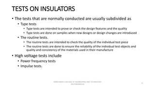
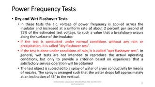
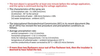
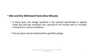
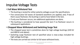
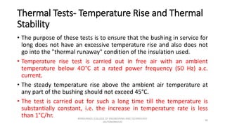
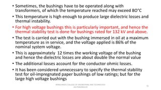
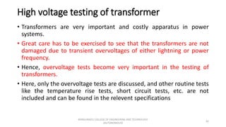
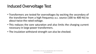
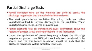
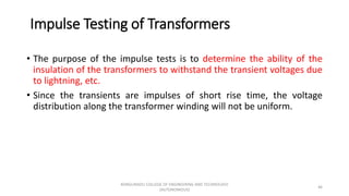
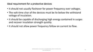
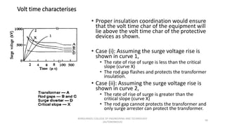
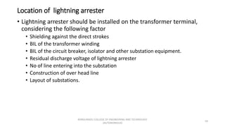
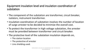
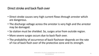
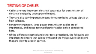
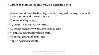
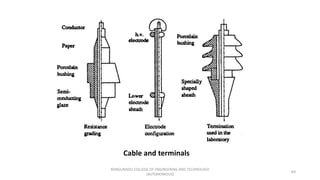
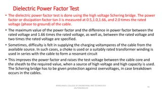
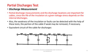
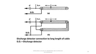
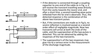
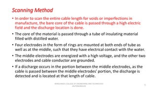
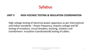
This document discusses high voltage testing and insulation coordination. It defines key terms related to high voltage testing such as disruptive discharge voltage, withstand voltage, and flashover voltage. It then describes various types of high voltage tests that are performed on electrical equipment, including power frequency tests, impulse tests, and pollution testing. Power frequency tests involve dry and wet flashover tests and withstand tests. Impulse tests include impulse withstand voltage tests and impulse flashover tests.
This document discusses power system protection schemes, including:
- Zones of protection with protective relays coordinated between zones
- Attributes of reliable, selective, and fast relaying
- Fault clearing times of relays and circuit breakers
- Protection of system components like feeders, transmission lines, transformers, generators
It provides examples of overcurrent protection design using time-graded and current-graded discrimination. Directional relays, differential protection, and power line carrier communication are also summarized.
This document discusses parallel resonance in an electrical circuit. It defines parallel resonance as occurring when circuit elements are connected in parallel with their inductance and capacitance, causing impedance to rise to a maximum at the resonant frequency. The resonant frequency is where the inductive and capacitive reactances are equal. At resonance, the parallel circuit acts resistive and the impedance is at its peak while the current is at its minimum. Key characteristics of a parallel resonant circuit including impedance, current, susceptance, and bandwidth are explained.
This document discusses polyphase circuits, including:
1. Polyphase circuits have multiple phases or windings that produce voltages displaced by equal electrical angles. Three-phase systems produce three voltages displaced by 120 degrees.
2. Star and delta connections are used to interconnect the phases. In a star connection, line voltage is 3 times phase voltage and line current equals phase current. In a delta connection, line voltage equals phase voltage and line current is 3 times phase current.
3. Three-phase systems have advantages over single-phase like constant power, greater output, cheaper transmission, and easier rectification for DC power.
This document discusses basic concepts in electrical circuits including charge, current, voltage, power, energy, circuit elements, resistors, capacitors, inductors, and circuit theorems. It defines:
- Charge as an electrical property measured in coulombs.
- Current as the motion of charge through a conductor measured in amperes.
- Voltage as the energy required to move charge from one point to another measured in volts.
- Power as the rate of expending or absorbing energy measured in watts.
- Basic circuit elements like resistors, capacitors, and inductors.
- Kirchhoff's laws and theorems for circuit analysis like Ohm's law, superposition, Theven
Qualidade energia - 105 Slides de conteúdo verdadeiramente relevanteSala da Elétrica
O documento discute os conceitos de qualidade da energia elétrica e os principais distúrbios que afetam essa qualidade, como variação de tensão, flicker, transientes, surtos e desequilíbrio de tensão. Explica como esses distúrbios impactam diferentes tipos de equipamentos e indústrias e quais são as soluções para melhorar a qualidade da energia ao longo da geração, transmissão, distribuição e uso.
A norma NBR5410 estabelece que a taxa máxima de ocupação da seção transversal de eletrodutos não deve exceder 53% para um condutor, 31% para dois condutores ou 40% para três ou mais condutores. O dimensionamento de eletrodutos envolve determinar as seções dos condutores, somar suas áreas e selecionar o diâmetro do eletroduto na tabela que acomode essa área total.
Introduction to reactive power control in electrical powerDr.Raja R
Introduction to reactive power control in electrical power
Reactive power in transmission line :
Reactive power control
Reactive power and its importance
Apparent Power
Reactive Power
Apparent Power
Reactive Power Formula
Insulation coordination involves selecting insulation strength for power system equipment that is consistent with expected overvoltages while obtaining an acceptable failure risk. This is achieved by determining the voltage-time characteristics of equipment and protective devices and positioning their curves such that devices protect connected equipment. A statistical approach relates the distribution of overvoltages to insulation breakdown probabilities to determine a suitable insulation level expressed as a withstand voltage where the risk of failure is very small.
This document discusses gas insulated substations (GIS). It provides an overview of conventional air insulated substations and their limitations, leading to the need for GIS. A GIS uses sulfur hexafluoride (SF6) gas as the insulating medium within an enclosed steel housing. It describes the essential components of a GIS and their assembly. Key advantages of GIS include occupying less space and being more reliable than conventional substations. The document also outlines some design challenges and drawbacks of GIS, as well as environmental concerns around the use of SF6 gas.
Earth resistance is a key parameter in determining the efficiency of earthing systems. In this application note we look at the measurement of earth resistance.
After a description of some universal fundamentals (e.g. standards, error margins and the influence of the weather), various measurement methods are discussed. A common feature of all the methods is that they determine the earth impedance by measuring the voltage across the earthing system for a known test current. Apart from that, there is a wide degree of variation in the internal circuitry of the measuring instruments used and the layout and arrangement of the external measuring circuit. A major distinction can be made between methods that draw current directly from the supply, and those methods that don’t.
Each method has its own particular disadvantages such as limited applicability, electric shock hazard, larger measurement errors, or requiring more time and effort to complete. The various advantages and disadvantages of the individual measurement techniques are described in the final chapters of this application note.
Power quality refers to maintaining the electric power within acceptable tolerances to allow devices to function properly without loss of performance. It is defined by parameters such as voltage, frequency and purity of waveform. Poor power quality can be caused by issues like sags, swells, transients, harmonics and grounding problems. The susceptibility of electrical equipment depends on the weakest component. While all devices are susceptible to some degree, the goal is to balance maintaining adequate power quality with designing equipment to have sufficient immunity to power quality issues.
O documento descreve as características e componentes das máquinas de corrente contínua. Explica que atualmente são mais usadas como geradores durante frenagem e reversão de motores. Também descreve os principais tipos de motores CC, incluindo excitação paralela, série e independente, e suas aplicações típicas.
Chapter 4 mechanical design of transmission linesfiraoltemesgen1
This chapter discusses the mechanical design of transmission lines. It covers various topics such as types of conductors, line supports, spacing between conductors, and sag-tension calculations. The key conductors mentioned are copper, aluminum, and steel. Wooden poles, steel tubular poles, reinforced concrete poles, and steel towers are described as the main types of line supports. The document also discusses the effects of wind and ice loading on transmission lines. Sag-tension calculations are explained using catenary curve equations.
This document discusses five types of transformer testing: open circuit testing, short circuit testing, load testing of single phase transformers, Sumpner's testing, and polarity testing. Open circuit testing determines losses with one winding open. Short circuit testing determines copper losses at full load. Load testing determines efficiency and regulation characteristics. Sumpner's testing uses two identical transformers to determine iron and copper losses. Polarity testing determines if the transformer windings produce voltages that are additive or subtractive.
Effect of earth on transmission line, bundle conductor & method of gmdvishalgohel12195
Effect of earth on transmission line, Bundle conductor & Method of GMD
EFFECTS OF EARTH ON THE CAPACITANCE OF THREE PHASE TRANSMISSION LINES
Bundle Conductors
DC biasing applies fixed voltages to transistors to place them in an operating region for amplification. The operating point defines the transistor's quiescent operating conditions under DC. Stability refers to a circuit's insensitivity to parameter variations like temperature. Emitter-stabilized and voltage divider biasing improve stability over fixed biasing by incorporating an emitter or voltage divider resistor. Feedback biasing further increases stability by introducing negative feedback from collector to base.
Design aspects of high voltage transmission linejournalBEEI
The transmission lines are very important in the transmitted of electrical power, and the process of selecting the voltage of the line is an important task in the design and implementation process. The process of transferring electrical power from one side then onto the next place for long away. While maintaining the percentage regulation within the permissible limits is an important problem in the transfer of energy. In electrical transmission line there are important elements are resistance, inductance and capacitance. The purpose of this paper is to study and calculate economic high-tension voltage and selection of overhead line conductor ACSR.
This document discusses different types of AC voltage controllers. It begins by introducing AC voltage controllers and how they can control power flow into a load by varying the RMS value of the load voltage using thyristors. It then describes the main types of AC voltage controllers classified by input supply type and control method. Applications such as lighting, heating and motor speed control are also outlined. The document proceeds to explain the principles and techniques of on-off control and phase control. Circuit diagrams are provided to illustrate single phase and three phase controller configurations. The document concludes by briefly discussing cycloconverters which can provide a variable output voltage and frequency.
The document describes two types of AC lap windings for electrical machines:
1) A single-phase, single-layer lap winding is developed for a 4-pole, 24-slot AC machine. The winding table is provided.
2) A double-layer lap winding is developed for a 3-phase, 4-pole, 24-slot AC machine. The slot distribution and winding table for the RYB phases are provided. A diagram of the complete main winding is included.
1. This document provides specifications for 1N4001-1N4007 general purpose rectifiers made by Fairchild Semiconductor, including maximum ratings, electrical characteristics, features, typical characteristics, and disclaimer information.
2. The rectifiers have low forward voltage drop and high surge current capability. Key parameters specified include forward voltage, reverse current, total capacitance, peak reverse voltage rating, average rectified forward current, and non-repetitive peak forward surge current.
3. Graphs show characteristics like forward voltage vs. forward current, non-repetitive surge current vs. number of cycles, and average rectified forward current vs. ambient temperature.
Performance of 400 kV line insulators under pollution | PDF | DOC | PPTSeminar Links
Visit https://seminarlinks.blogspot.com to download.
Outdoor insulators are subjected to nature Polluted environmental contaminants, which may include sea salt, cement dust, fly ash, birds droppings, industrial emissions etc. deposit on their surface With the increasing industrialization not only the degree of pollution but also the type of pollution has an effect on the performance of the insulators.
This document discusses power electronics and various types of rectifiers. It covers topics such as diode rectifiers, controlled rectifiers, rectifier performance parameters, single-phase and three-phase rectifiers, and applications of single-phase controlled rectifiers in battery chargers. Diode and thyristor-based rectifiers are classified as uncontrolled and controlled rectifiers. Key performance parameters discussed include form factor, efficiency, ripple factor, and transformer utilization factor. Circuit diagrams and voltage and current waveforms of half-wave, full-wave, and bridge rectifiers are presented.
The document discusses various types of tests conducted on isolators, bushings, cables, and circuit breakers. Key tests include:
1. Power frequency and impulse voltage withstand tests to check the insulation strength of isolators, bushings, and cables.
2. Partial discharge and tan delta tests to evaluate insulation condition and dielectric losses.
3. Short circuit tests on circuit breakers to check their ability to safely interrupt fault currents under different voltage and current conditions.
4. Other tests include temperature rise, mechanical endurance, and measurement of electrical characteristics.
The document discusses electromagnetic compatibility (EMC) immunity testing standards. It focuses on electrostatic discharge (ESD), electrical fast transients (EFT), surge, radiated immunity, and conducted immunity tests. For each test, it describes the purpose, needed equipment, test setup, procedures, performance criteria, standards, and other test considerations. The performance criteria classify immunity test results into four categories based on the equipment's performance.
High voltage testing is important for ensuring insulation can withstand transient overvoltages. There are several types of high voltage tests:
(1) Power frequency tests include dry and wet flashover tests and withstand tests to determine insulation withstand capability under normal and wet conditions.
(2) Impulse tests involve applying standard impulse voltages to determine insulation withstand under transient overvoltages like lightning.
(3) Partial discharge testing locates internal insulation weaknesses by detecting and measuring electrical discharges within insulation.
Type tests are comprehensive tests conducted on protection equipment by manufacturers to prove relays meet specifications and standards. These involve testing hardware and software under various conditions. Routine factory tests check for defects during manufacturing. Commissioning and periodic maintenance tests ensure proper functioning when relays are installed and over time.
HIGH VOL TAGE TESTING OF TRANSFORMER BY HARI SHANKAR SINGHShankar Singh
1. The document discusses high voltage testing of electrical transformers, including various types of tests like partial discharge testing, impulse testing, turns ratio testing, and insulation resistance testing.
2. These tests help check the insulation quality, detect defects, verify voltage ratios, and ensure transformers can withstand high voltage surges to prevent failures.
3. High voltage testing provides advantages like improved safety, energy efficiency, lower costs, and failure detection; but can also have disadvantages like not removing the root causes of failures.
This document discusses high voltage testing that is needed on ships to ensure reliability and safety of HV systems. It describes several types of common HV tests: insulation resistance testing to measure insulation integrity; polarity index testing for more detailed insulation measurements; infrared imaging to detect hotspots; circuit breaker testing; and partial discharge testing to detect early insulation issues. Proper procedures are outlined for each test to safely isolate, ground, and conduct the tests.
Circuit breaker testing is necessary to verify their performance under normal and abnormal conditions. There are two main types of tests: type tests to prove design features and quality, and routine tests to check for defects. Routine tests include mechanical endurance, thermal, dielectric, short circuit, and measurement of resistance tests. Proper preparation and equipment such as a short circuit generator, transformer, and measuring instruments are required to perform circuit breaker testing.
AC High voltage Air Break Disconnector Switch Routine Test According to IEC 6...Ali Sepehri
AC High voltage Air Break Disconnector Switch Routine Test According to IEC 62271-102 Standard
Article 9(09.10.2018) direct link: https://lnkd.in/gX_aVqq
The document discusses various types of electrical test equipment used to test circuits and electrical components. It describes multimeters, megohmmeters, low-resistance ohmmeters, hipotential test sets, high current test sets, secondary test sets, relay test sets, power factor test sets, winding resistance test sets, current transformer test sets, ground resistance test sets, and power recorders. The document provides details on what each type of test equipment is used for and how measurements are made.
Non-destructive testing (NDT) involves analysis techniques used to evaluate materials, components, or systems without damaging them. NDT is used to determine properties like resistivity, dielectric constant, and loss factor of insulating materials. It helps ensure materials maintain their insulating properties during operation. Two common methods for measuring dielectric loss and loss angle of insulating materials are the Schering bridge and transformer ratio arm bridge. The loss angle tan δ indicates the quality of insulation and can determine material life expectancy. Partial discharges within insulating materials are detected using NDT and indicate weaknesses.
This document discusses various tests performed on surge diverters/lightning arresters to ensure they function properly. It describes tests such as the power frequency spark over test to check insulation, the 100% standard impulse spark over test to check operation during transient overvoltages, and residual voltage and high current impulse tests on pro-rated units. Other mechanical, pressure relief, and pollution tests are also conducted to test important properties. The conclusion is that understanding these various tests provides knowledge about surge diverter ratings and testing.
This document discusses testing of transformers. It provides an overview of transformers and their functions in transmission and distribution of electrical energy. It then describes various routine, type, and special tests performed on transformers, including winding resistance measurement, voltage ratio measurement, no-load loss measurement, load loss measurement, insulation resistance measurement, and dielectric tests. It also discusses short-circuit testing procedures and criteria. Temperature rise testing and its limits are also summarized.
Installation, Testing and Troubleshooting of TransformersLiving Online
The document discusses the installation, testing, and troubleshooting of transformers. It describes the different types of tests performed on transformers, including routine tests, type tests, and special tests. Routine tests check characteristics like winding resistance, voltage ratios, losses, and insulation. Special tests examine properties such as dielectric strength, capacitance, and harmonics. The document also outlines standards and procedures for testing, as well as limits for temperature rise and requirements for insulating oil.
1) Tan delta testing uses a very low frequency AC voltage to measure the dissipation factor of insulation to determine its quality and condition. A higher loss angle indicates more contamination.
2) The cable or winding is disconnected and the test voltage is applied and increased in steps while tan delta measurements are taken. A straight trend line indicates healthy insulation while a rising line indicates contamination.
3) Routine maintenance of bushings includes inspecting the porcelain for cracks, metal parts for corrosion, oil levels, and cleaning surface contamination which can cause flashovers. Leaks should be repaired to prevent moisture issues.
The document discusses diagnostic testing and monitoring of power transformers. It describes how diagnostic testing and monitoring helps determine a transformer's condition and identify corrective measures to ensure reliable operation and extend lifespan. Various influences like thermal, aging, mechanical, electrical, and protection problems can negatively impact a transformer's expected lifetime. Testing and corrective measures discussed include maintaining auxiliary components, reconditioning insulation, and replacing parts.
This document discusses tests performed on transformers and surge arresters, including induced voltage tests, partial discharge tests, impulse tests, and surge arrester tests like spark over tests and residual voltage tests. The tests are used to evaluate the insulation strength and ability to withstand transient overvoltages of transformers and effectiveness of surge arresters in protecting equipment.
Field tests are conducted on electrical equipment after installation and during routine maintenance to assess its condition and safety. There are several types of field tests, including acceptance tests for new equipment, routine maintenance tests performed regularly, and special maintenance tests for known issues. The tests evaluate insulation integrity, device functionality, circuit performance over time, and other factors. Common testing methods involve applying voltage to insulation, analyzing insulating liquids, ensuring proper relay and breaker operation, measuring time-current curves, evaluating ground resistance, detecting fault gases, and using infrared scans. The results are used to determine corrective actions, benchmark equipment health, and verify design standards are met.
The high potential test is used to detect weak spots in machine insulation like stator or rotor windings. An AC voltage is preferably applied at 2 times the line-to-line operating voltage plus 1 kV for new windings, and at reduced voltages for older windings, to stress the insulation without causing breakdown. The voltage is slowly increased over 10 seconds to the test level and held for 1 minute. Proper safety precautions must be followed when using high voltages for this test.
Insulation resistance testing measures the resistivity of transformer insulation to verify acceptability and detect damage. The test involves measuring insulation resistance values at specific time intervals and calculating the polarization index. Acceptable polarization index values indicate good insulation dryness and condition, while lower values suggest issues. Proper cleaning, connections, and safety precautions are important when performing the test.
Similar to HVE UNIT V HIGH VOLTAGES TESTING AND INSULATION COORDINATION.pptx (20)
PE UNIT V - AC VOLTAGE CONTROLLERS AND CYCLOCONVERTERS.pptMuthuKumar158260
This document discusses various AC voltage controllers and cycloconverters. It covers single phase unidirectional and bidirectional controllers, PWM control for power factor control, multistage sequence control of voltage controllers using two stage sequence control, step up and step down cycloconverters for single phase to single phase, three phase to single phase, and three phase to three phase conversions, matrix converters, and applications of AC to AC converters in welding.
Power electronics deals with controlling and converting electric power using solid-state electronics. It involves power equipment for generation, transmission and distribution as well as electronic devices and circuits for signal processing and control objectives. Some key developments include the mercury arc rectifier in 1900, silicon transistor in 1948, and thyristor or SCR in 1956. Power electronic converters are now used for applications like UPS, motor speed control, power transmission, and power supplies due to advantages like fast response, high efficiency and compact size, though they can generate harmonics and have low power factors requiring correction. Power electronic converters work by classifying and controlling the operation of power semiconductor devices like power diodes, SCRs, BJTs, MOSFETs
This document discusses different types of inverters used in power electronics. It describes that an inverter converts DC power to AC power at a desired output voltage and frequency. It then classifies inverters as line-commutated and force-commutated. Various inverter circuits are presented including half-bridge, full-bridge, and three-phase inverters. The 180 and 120 degree modes of operation for three-phase inverters are explained. Pulse width modulation techniques for inverters like sinusoidal PWM and modified sinusoidal PWM are introduced. Current source inverters are also briefly discussed.
This document discusses different types of controlled rectifiers used in power electronics. It describes:
1) Controlled rectifiers use thyristors instead of diodes for AC to DC conversion and are classified as single phase, three phase, based on quadrant operation, and number of pulses.
2) Applications include DC motor speed control, DC power supplies, electrochemical processes, traction, and HVDC transmission.
3) Circuit diagrams and waveforms are presented for single phase and three phase half wave and full wave rectifiers with resistive and inductive loads. Phase control is used to vary the output voltage.
This document discusses different types of choppers used in power electronics. It describes the principle of operation of choppers and their commutation methods including voltage commutation, current commutation, and load commutation. Specific chopper circuits are explained such as the voltage commutated chopper and current commutated chopper. Multiphase choppers and their operating modes are also introduced. Finally, different types of switching mode regulators including buck, boost, buck-boost, and Cuk regulators are classified.
This document discusses digital signal processors and their architecture. It describes the architecture of TMS320C5x digital signal processors, including their bus structure, central processing unit components like the central arithmetic logic unit and parallel logic unit, on-chip memory, and applications like speech processing and biomedical signal processing. Key features of the TMS320C5x like separate program and data buses, memory-mapped registers, and dual access RAM are summarized.
This document discusses the design of digital filters including IIR and FIR filters. It covers various IIR filter structures and design methods like impulse invariant and bilinear transformation. It specifically discusses the design of low pass Butterworth and Chebyshev filters. For Butterworth filters, it explains that higher order filters more closely approximate the ideal filter characteristic. It provides the design procedure for a low pass digital Butterworth filter including selecting the order and determining the Butterworth polynomial. For Chebyshev filters, it explains that the analog filter is first designed and then transformed to the digital domain using impulse invariant or bilinear transformations.
The document provides an overview of discrete time signal processing concepts including:
1) Signals can be classified as continuous, discrete, deterministic, random, periodic, and non-periodic. Systems can be linear, time-invariant, causal, stable/unstable, and recursive/non-recursive.
2) Digital signal processing has advantages over analog such as precision, stability and easy implementation of operations. It also has drawbacks like needing ADCs/DACs and being limited by sampling frequency.
3) Discrete time signals are only defined at discrete time instances while continuous time signals are defined for all time. Both can be represented graphically, functionally, through tables or sequences.
DTSP UNIT III - DISCRETE FOURIER TRANSFORM AND COMPUTATION.pptxMuthuKumar158260
This document discusses discrete Fourier transforms and computation. It covers structures of IIR filter realization including direct form-I, direct form-II, parallel and cascade forms. It also discusses IIR filter design using impulse invariant and bilinear transformation methods. Additionally, it outlines FIR design including linear phase filters and windowing techniques using rectangular, Hamming and Hanning windows. Furthermore, it details properties of the discrete Fourier transform and fast Fourier transform algorithms like radix-2 DIT and DIF and provides examples of 8-point DFT calculations using these algorithms.
DTSP UNIT II - DISCRETE TIME SYSTEM ANALYSIS.pptxMuthuKumar158260
This document discusses discrete time system analysis and the Z-transform. It introduces the Z-transform as the discrete-time counterpart of the Laplace transform, which is used to represent and analyze linear time-invariant discrete-time systems. The Z-transform is used to convert difference equations in the time domain to algebraic equations in the Z-domain, which can then be more easily solved and converted back to the time domain using the inverse Z-transform. The document also notes that the Z-transform generalizes the discrete-time Fourier transform and is well-suited for solving difference equations with initial conditions.
HVE UNIT III GENERATION OF HIGH VOLTAGES AND HIGH CURRENTS.pptxMuthuKumar158260
This document discusses various methods for generating high voltages and currents. It describes how high direct current (DC) voltages can be generated using rectifiers, voltage multipliers, and van de Graaff generators. High impulse voltages can be produced with Marx circuits, and high alternating current (AC) voltages can be achieved with cascaded transformers, resonant transformers, and Tesla coils. Half-wave and full-wave rectifiers as well as voltage doubler and multiplier circuits are explained for boosting DC voltages. Cockcroft-Walton circuits are highlighted as a type of voltage multiplier that can significantly increase an input voltage through multiple stages.
The document discusses various types of materials used as dielectric insulators in electrical engineering. It describes organic materials like paper and pressboard, inorganic materials like glass and ceramics, and synthetic polymers like polyethylene, PTFE, and nylon. These materials are used as solid insulators in electrical equipment due to their high resistivity, low dielectric losses, and ability to withstand varying environmental conditions. The document provides details on the electrical and mechanical properties of different insulating materials.
HVE UNIT I OVER VOLTAGES IN ELECTRICAL POWER SYSTEM.pptMuthuKumar158260
High voltages are used in power systems, industry, and research for applications like power transmission over long distances. Overvoltages in electrical power systems can be caused by external sources like lightning or internal sources during switching operations. Lightning occurs due to buildup and discharge of electric charges between clouds or from clouds to the ground. Switching surges are generated internally during the connecting or disconnecting of transmission lines and equipment. Methods to control overvoltages include using resistors during line energization, phase-controlled switching, draining trapped charges before reclosing lines, and installing surge arresters.
HVE UNIT IV MEASUREMENT OF HIGH VOLTAGES AND HIGH CURRENTS.pptxMuthuKumar158260
The document discusses various techniques for measuring high voltages and currents. It describes methods such as using high resistance series connections with microammeters, resistance potential dividers, capacitance potential dividers, generating voltmeters, and electrostatic voltmeters. It also discusses techniques for measuring high alternating currents and impulse voltages, including the use of peak voltmeters and sphere gaps.
Using recycled concrete aggregates (RCA) for pavements is crucial to achieving sustainability. Implementing RCA for new pavement can minimize carbon footprint, conserve natural resources, reduce harmful emissions, and lower life cycle costs. Compared to natural aggregate (NA), RCA pavement has fewer comprehensive studies and sustainability assessments.
Understanding Inductive Bias in Machine LearningSUTEJAS
This presentation explores the concept of inductive bias in machine learning. It explains how algorithms come with built-in assumptions and preferences that guide the learning process. You'll learn about the different types of inductive bias and how they can impact the performance and generalizability of machine learning models.
The presentation also covers the positive and negative aspects of inductive bias, along with strategies for mitigating potential drawbacks. We'll explore examples of how bias manifests in algorithms like neural networks and decision trees.
By understanding inductive bias, you can gain valuable insights into how machine learning models work and make informed decisions when building and deploying them.
KuberTENes Birthday Bash Guadalajara - K8sGPT first impressionsVictor Morales
K8sGPT is a tool that analyzes and diagnoses Kubernetes clusters. This presentation was used to share the requirements and dependencies to deploy K8sGPT in a local environment.
CHINA’S GEO-ECONOMIC OUTREACH IN CENTRAL ASIAN COUNTRIES AND FUTURE PROSPECTjpsjournal1
The rivalry between prominent international actors for dominance over Central Asia's hydrocarbon
reserves and the ancient silk trade route, along with China's diplomatic endeavours in the area, has been
referred to as the "New Great Game." This research centres on the power struggle, considering
geopolitical, geostrategic, and geoeconomic variables. Topics including trade, political hegemony, oil
politics, and conventional and nontraditional security are all explored and explained by the researcher.
Using Mackinder's Heartland, Spykman Rimland, and Hegemonic Stability theories, examines China's role
in Central Asia. This study adheres to the empirical epistemological method and has taken care of
objectivity. This study analyze primary and secondary research documents critically to elaborate role of
china’s geo economic outreach in central Asian countries and its future prospect. China is thriving in trade,
pipeline politics, and winning states, according to this study, thanks to important instruments like the
Shanghai Cooperation Organisation and the Belt and Road Economic Initiative. According to this study,
China is seeing significant success in commerce, pipeline politics, and gaining influence on other
governments. This success may be attributed to the effective utilisation of key tools such as the Shanghai
Cooperation Organisation and the Belt and Road Economic Initiative.
Harnessing WebAssembly for Real-time Stateless Streaming PipelinesChristina Lin
Traditionally, dealing with real-time data pipelines has involved significant overhead, even for straightforward tasks like data transformation or masking. However, in this talk, we’ll venture into the dynamic realm of WebAssembly (WASM) and discover how it can revolutionize the creation of stateless streaming pipelines within a Kafka (Redpanda) broker. These pipelines are adept at managing low-latency, high-data-volume scenarios.
Advanced control scheme of doubly fed induction generator for wind turbine us...IJECEIAES
This paper describes a speed control device for generating electrical energy on an electricity network based on the doubly fed induction generator (DFIG) used for wind power conversion systems. At first, a double-fed induction generator model was constructed. A control law is formulated to govern the flow of energy between the stator of a DFIG and the energy network using three types of controllers: proportional integral (PI), sliding mode controller (SMC) and second order sliding mode controller (SOSMC). Their different results in terms of power reference tracking, reaction to unexpected speed fluctuations, sensitivity to perturbations, and resilience against machine parameter alterations are compared. MATLAB/Simulink was used to conduct the simulations for the preceding study. Multiple simulations have shown very satisfying results, and the investigations demonstrate the efficacy and power-enhancing capabilities of the suggested control system.
Low power architecture of logic gates using adiabatic techniquesnooriasukmaningtyas
The growing significance of portable systems to limit power consumption in ultra-large-scale-integration chips of very high density, has recently led to rapid and inventive progresses in low-power design. The most effective technique is adiabatic logic circuit design in energy-efficient hardware. This paper presents two adiabatic approaches for the design of low power circuits, modified positive feedback adiabatic logic (modified PFAL) and the other is direct current diode based positive feedback adiabatic logic (DC-DB PFAL). Logic gates are the preliminary components in any digital circuit design. By improving the performance of basic gates, one can improvise the whole system performance. In this paper proposed circuit design of the low power architecture of OR/NOR, AND/NAND, and XOR/XNOR gates are presented using the said approaches and their results are analyzed for powerdissipation, delay, power-delay-product and rise time and compared with the other adiabatic techniques along with the conventional complementary metal oxide semiconductor (CMOS) designs reported in the literature. It has been found that the designs with DC-DB PFAL technique outperform with the percentage improvement of 65% for NOR gate and 7% for NAND gate and 34% for XNOR gate over the modified PFAL techniques at 10 MHz respectively.
Introduction- e - waste – definition - sources of e-waste– hazardous substances in e-waste - effects of e-waste on environment and human health- need for e-waste management– e-waste handling rules - waste minimization techniques for managing e-waste – recycling of e-waste - disposal treatment methods of e- waste – mechanism of extraction of precious metal from leaching solution-global Scenario of E-waste – E-waste in India- case studies.
HEAP SORT ILLUSTRATED WITH HEAPIFY, BUILD HEAP FOR DYNAMIC ARRAYS.
Heap sort is a comparison-based sorting technique based on Binary Heap data structure. It is similar to the selection sort where we first find the minimum element and place the minimum element at the beginning. Repeat the same process for the remaining elements.
Technical Drawings introduction to drawing of prisms
HVE UNIT V HIGH VOLTAGES TESTING AND INSULATION COORDINATION.pptx
1. EE8701 - HIGH VOLTAGE
ENGINEERING
1
KONGUNADU COLLEGE OF ENGINEERING AND TECHNOLOGY
(AUTONOMOUS)
2. UNIT – V
HIGH VOLTAGES TESTING AND INSULATION
COORDINATION
2
KONGUNADU COLLEGE OF ENGINEERING AND TECHNOLOGY
(AUTONOMOUS)
3. Syllabus
UNIT V HIGH VOLTAGE TESTING & INSULATION COORDINATION
High voltage testing of electrical power apparatus as per International
and Indian standards – Power frequency, impulse voltage and DC
testing of Insulators, circuit breakers, bushing, isolators and
transformers- Insulation Coordination& testing of cables.
3
KONGUNADU COLLEGE OF ENGINEERING AND TECHNOLOGY
(AUTONOMOUS)
4. Need for Testing for Over Voltages
• It is essential to ensure that the electrical equipment is capable of
withstanding the overvoltages that are met with in service.
• The overvoltages may be either due to natural causes like lightning or
system originated ones such as switching or power frequency
transient voltages. Hence, testing for overvoltages is necessary.
4
KONGUNADU COLLEGE OF ENGINEERING AND TECHNOLOGY
(AUTONOMOUS)
5. Definitions
• Disruptive Discharge Voltage
• Withstand Voltage
• Fifty Per Cent Flashover Voltage
• Hundred Per Cent Flashover Voltage
• Creepage Distance
• A.C. Test Voltages
• Impulse Voltages
• Reference Atmospheric Conditions
5
KONGUNADU COLLEGE OF ENGINEERING AND TECHNOLOGY
(AUTONOMOUS)
6. • Disruptive Discharge Voltage
• This is defined as the voltage which produces the loss of dielectric strength of
an insulation.
• It is that voltage at which the electrical stress in the insulation causes a failure
which includes the collapse of voltage and passage of current.
• In solids, this causes a permanent loss of strength, and in liquids or gases only
temporary loss may be caused.
• When a discharge takes place between two electrodes in a gas or a liquid or
over a solid surface in air, it is called flashover.
• If the discharge occurs through a solid insulation it is called puncture.
• Withstand Voltage
• The voltage which has to be applied to a test object under specified
conditions in a withstand test is called the withstand voltage [as per IS: 731
and IS: 2099-1963].
6
KONGUNADU COLLEGE OF ENGINEERING AND TECHNOLOGY
(AUTONOMOUS)
7. • Flashover Voltage
• The voltage that causes a flashover at each or its application under specified
conditions when applied to test object.
• Fifty Per Cent Flashover Voltage
• This is the voltage which has a probability of 50% flashover, when applied to a
test object.
• This is normally applied in impulse tests in which the loss of insulation
strength is temporary
• Hundred Per Cent Flashover Voltage
• The voltage that causes a flashover at each of its applications under specified
conditions when applied to test objects as specified is hundred per cent
flashover voltage.
• Creepage Distance
• It is the shortest distance on the contour of the external surface of the
insulator unit or between two metal fittings on the insulator.
7
KONGUNADU COLLEGE OF ENGINEERING AND TECHNOLOGY
(AUTONOMOUS)
8. • Wet and Dry Power Frequency Test
• In these tests, the voltage specified in the specifications is applied under dry or wet
conditions for a specified period. The test object withstand the voltage.
• A.C. Test Voltages
• Alternating test voltages of power frequency should have a frequency range of 40 to 60
Hz and should be approximately sinusoidal.
• The deviation allowed from the standard sine curve is about 7%. The deviation is
checked by measuring instantaneous values over specified intervals and computing the
rms value, the average value, and the form factor.
• Impulse Voltages
• Impulse voltages are characterized by polarity, peak value, time to front (tf), and time to
half the peak value after the peak (tt).
• The time to front is defined as 1.67 times to time between 30% and 90% of the peak
value in the rising portion of the wave.
• standard impulse wave is defined as one with tf = 1.2 μs, ttt = 50 μs
• The tolerances allowed are ±3% on the peak value, ±30% in the front time (tf), and ±20%
in the tail time (tf).
8
KONGUNADU COLLEGE OF ENGINEERING AND TECHNOLOGY
(AUTONOMOUS)
9. • Reference Atmospheric Conditions
• The electrical characteristics of the insulators and other apparatus are
normally referred to the reference atmospheric conditions.
• According to the Indian Standard Specifications, they are:
• Temperature : 27˚C
• Pressure : 1013 millibars (or 760 torr)
• Absolute humidity : 17 gm/m3
• Since it is not always possible to do tests under these reference
conditions, correction factors have to be applied.
• In some cases, the following test conditions are also used as reference
(British Standard Specifications) conditions.
• Temperature : 2O˚C
• Pressure : 1013 millibars (760 Torr)
• Absolute humidity : 11 g/m3 (65% relative humidity at 2O0C)
Indian and International Standard Specifications
9
KONGUNADU COLLEGE OF ENGINEERING AND TECHNOLOGY
(AUTONOMOUS)
11. TESTS ON INSULATORS
• The tests that are normally conducted are usually subdivided as
• Type tests
• Type tests are intended to prove or check the design features and the quality
• Type tests are done on samples when new designs or design changes are introduced
• The routine tests.
• The routine tests are intended to check the quality of the individual test piece
• The routine tests are done to ensure the reliability of the individual test objects and
quality and consistency of the materials used in their manufacture
• High voltage tests include
• Power frequency tests
• Impulse tests.
11
KONGUNADU COLLEGE OF ENGINEERING AND TECHNOLOGY
(AUTONOMOUS)
12. Power Frequency Tests
• Dry and Wet Flashover Tests
• In these tests the a.c. voltage of power frequency is applied across the
insulator and increased at a uniform rate of about 2 percent per second of
75% of the estimated test voltage, to such a value that a breakdown occurs
along the surface of the insulator.
• If the test is conducted under normal conditions without any rain or
precipitation, it is called "dry flashover test".
• If the test is done under conditions of rain, it is called "wet flashover test". In
general, wet tests are not intended to reproduce the actual operating
conditions, but only to provide a criterion based on experience that a
satisfactory service operation will be obtained
• The test object is subjected to a spray of water of given conductivity by means
of nozzles. The spray is arranged such that the water drops fall approximately
at an inclination of 45° to the vertical.
12
KONGUNADU COLLEGE OF ENGINEERING AND TECHNOLOGY
(AUTONOMOUS)
13. • The test object is sprayed for at least one minute before the voltage application,
and the spray is continued during the voltage application.
• The characteristics of the spray are
(i) Precipitation rate : 3 ± 10% (mm/min)
(ii) direction : 45° to the vertical
(iii) conductivity of water : 100 micro Siemens ± 10%
(iv) water temperature : ambient ±15°C
• The International Electrotechnical Commission (IEC) in its recent document (No.
42 of 1972) has revised the test procedure and precipitation conditions as
follows.
• Average precipitation rate:
vertical component = 1 to 1.5 mm/min
horizontal component = 1 to 1.5 mm/min
limits for individual measurements = 0.5 to 2.0 mm/min.
temperature of collected water = ambient temperature ±15° C.
and the conductivity of water corrected to 2O° C = 100 ±15 micro Siemens
• If more than two flashovers occur out of five flashover test, then the insulator is
deemed to have failed the test.
13
KONGUNADU COLLEGE OF ENGINEERING AND TECHNOLOGY
(AUTONOMOUS)
14. • Wet and Dry Withstand Tests (One Minute)
• In these tests, the voltage specified in the relevant specification is applied
under dry and wet conditions for a period of one minute with an insulator
mounted as in service conditions.
• The test piece should withstand the specified voltage.
14
KONGUNADU COLLEGE OF ENGINEERING AND TECHNOLOGY
(AUTONOMOUS)
15. Impulse Tests
• Impulse Withstand Voltage Test
• This test is done by applying standard impulse voltage of specified value
under dry conditions with both positive and negative polarities of the wave.
• If five consecutive waves do not cause a flashover or puncture, the insulator is
deemed to have passed the test. If two applications cause flashover, the
object is deemed to have failed.
• If there is only one failure, additional ten applications of the voltage wave are
made. If the test object has withstood the subsequent applications, it is said
to have passed the test.
15
KONGUNADU COLLEGE OF ENGINEERING AND TECHNOLOGY
(AUTONOMOUS)
16. • Impulse Flashover Test
• The test is done as above with the specified voltage. Usually, the probability
of failure is determined for 40% and 60% failure values or 20% and 80%
failure values, since it is difficult to adjust the test voltage for the exact 50%
flashover values.
• The average value of the upper and the lower limits is taken.
• The insulator surface should not be damaged by these tests, but slight
marking on its surface or chipping off of the cement is allowed.
16
KONGUNADU COLLEGE OF ENGINEERING AND TECHNOLOGY
(AUTONOMOUS)
17. • Pollution Testing
• Because of the problem of pollution of outdoor electrical insulation and
consequent problems of the maintenance of electrical power systems,
pollution testing is gaining importance
• The normal types of pollution are
• dust, micro-organisms, bird secretions, flies, etc.,
• industrial pollution like smoke, petroleum vapours, dust, and other deposits,
• coastal pollution in which corrosive and hygroscopic salt layers are deposited on the
insulator surfaces,
• desert pollution in which sand storms cause deposition of sand and dust layers,
• ice and fog deposits at high altitudes and in polar countries.
• These pollutions cause corrosion, non-uniform gradients along the insulator
strings and surface of insulators and also cause deterioration of the material.
• Also, pollution causes partial discharges and radio interference. Hence,
pollution testing is important for extra high voltage systems.
17
KONGUNADU COLLEGE OF ENGINEERING AND TECHNOLOGY
(AUTONOMOUS)
18. • At present there is no standard pollution test available.
• The popular test that is normally done is the salt fog test.
Salt fog test
• In this test, the maximum normal withstand voltage is applied on the
insulator and then artificial salt fog is created around the insulator by jets
of salt water and compressed air.
• If the flashover occurs within one hour, the test is repeated with fog of
lower salinity, otherwise, with a fog of higher salinity.
• The maximum salinity at which the insulator withstands three out of four
tests without flashover is taken as the representative figure. Much work is
yet to be done to standardize the test procedures.
18
KONGUNADU COLLEGE OF ENGINEERING AND TECHNOLOGY
(AUTONOMOUS)
19. TESTING OF ISOLATORS AND CIRCUIT BREAKERS
• The definition of an Isolator or a Disconnector
• An isolator or a disconnector is a mechanical switching device, which provides
in the open position, an isolating distance in accordance with special
requirements.
• An isolator is capable of opening and closing a circuit when either negligible
current is broken or made or when no significant change in the voltage across
the terminals of each of the poles of the isolator occurs.
• It is also capable of carrying currents under normal circuit conditions, and
carrying for a specified time, currents under abnormal conditions such as
those of a short circuit.
19
KONGUNADU COLLEGE OF ENGINEERING AND TECHNOLOGY
(AUTONOMOUS)
20. • Testing of circuit breakers is intended to evaluate
• the constructional and operational characteristics
• the electrical characteristics of the circuit which the switch or the breaker has
to interrupt or make
• The different characteristics of a circuit breaker or a switch may be summarized
as per the following groups.
• The electrical characteristics which determine the arcing voltage, the current
chopping characteristics, the residual current, the rate of decrease of
conductance of the arc space and the plasma, and the shunting effects in
interruption.
• Other physical characteristics including the media in which the arc is
extinguished, the pressure developed or impressed at the point of interruption,
the speed of the contact travel, the number of breaks, the size of the arcing
chamber, and the materials and configuration of the circuit interruption.
20
KONGUNADU COLLEGE OF ENGINEERING AND TECHNOLOGY
(AUTONOMOUS)
21. • The characteristics of the circuit include the degree of electrical loading, the
normally generated or applied voltage, the type of fault in the system which the
breaker has to clear, the time of interruption, the time constant, the natural
frequency and the power factor of the circuit, the rate of rise of recovery voltage,
the restriking voltage, the decrease in the a.c. component of the short circuit
current, and the degree of asymmetry and the d.c. component of the short circuit
current
• The main tests conducted on the circuit breakers and isolator
switches are
• the dielectric tests or overvoltage tests
• the temperature rise tests
• the mechanical tests
• the short circuit tests
21
KONGUNADU COLLEGE OF ENGINEERING AND TECHNOLOGY
(AUTONOMOUS)
22. • Dielectric tests
• It consist of overvoltage withstand tests of power frequency, lightning and
switching impulse voltages.
• Tests are done for both internal and external insulation with the switch or
circuit breaker in both the open and closed positions.
• In the open position, the test voltage levels are 15% higher than the test
voltages used when the breaker is in closed position.
• As such there is always the possibility of line to ground flashover.
• To avoid this, the circuit breaker is mounted on insulators above the ground,
and hence the insulation level of the body of the circuit breaker is raised
22
KONGUNADU COLLEGE OF ENGINEERING AND TECHNOLOGY
(AUTONOMOUS)
23. • Temperature rise and mechanical tests
• Rated current is passed continuously for a long period. The temperature
readings are taken by using thermocouple.
• If the temperature is within the specified value, then the switchgear is said to
have passed the test.
• In mechanical test, the circuit breaker and isolator must open and close at the
correct speed and perform operations without mechanical failures.
• The impulse tests
• The lightning impulse wave of standard shape are done in a similar manner as
in the case of insulators.
• In addition, the switching surge tests with switching overvoltages are done on
circuit breakers and isolators to assess their performance under overvoltages
due to switching operations.
23
KONGUNADU COLLEGE OF ENGINEERING AND TECHNOLOGY
(AUTONOMOUS)
24. Short Circuit Tests of isolators and circuit breaker
• The most important tests carried out on circuit breakers are short
circuit tests, since these tests assess the primary performance of
these devices, i.e. their ability to safely interrupt the fault currents.
• These tests consists of determining the making and breaking
capacities at various load currents and rated voltages.
• In the case of isolators, the short circuit tests are conducted only with
the limited purpose to determine their capacity to carry the rated
short circuit current for a given duration; and no breaking or making
current test is done
24
KONGUNADU COLLEGE OF ENGINEERING AND TECHNOLOGY
(AUTONOMOUS)
25. • The different methods of conducting short circuit tests are
• (I) Direct Tests
• (a) using a short circuit generator as the source
• (b) using the power utility system or network as the source.
• (II) Synthetic Tests
• a)Direct Testing in the Networks or in the Fields
• Circuit breakers are sometimes tested for their ability to make or break
the circuit under normal load conditions or under short circuit conditions
in the network itself.
• This is done during period of limited energy consumption or when the
electrical energy is diverted to other sections of the network which are
not connected to the circuit under test.
25
KONGUNADU COLLEGE OF ENGINEERING AND TECHNOLOGY
(AUTONOMOUS)
26. • The advantages of field tests are:
• The circuit breaker is tested under actual conditions like those that occur in a
given network.
• Special occasions like breaking of charging currents of long lines, very short
line faults, interruption of small inductive currents, etc. can be tested by
direct testing only.
• to assess the thermal and dynamics effects of short circuit currents, to study
applications of safety devices, and to revise the performance test procedures,
etc.
• The disadvantages are:
• The circuit breaker can be tested at only a given rated voltage and network capacity.
• The necessity to interrupt the normal services and to test only at light load
conditions.
• Extra inconvenience and expenses in installation of controlling and measuring
equipment in the Held.
26
KONGUNADU COLLEGE OF ENGINEERING AND TECHNOLOGY
(AUTONOMOUS)
27. b) Direct Testing in Short Circuit Test Laboratories
• In order to test the circuit breakers at different voltages and at
different short circuit currents, short circuit laboratories are provided.
The schematic layout of a short circuit testing laboratory is given in
Fig.
27
KONGUNADU COLLEGE OF ENGINEERING AND TECHNOLOGY
(AUTONOMOUS)
28. • It consists of a short circuit
generator in association with a
master circuit breaker, resistors,
reactors and measuring devices.
• A make switch initiates the short
circuit and the master circuit
breaker isolates the test device
from the source at the end of a
predetermined time set on a test
sequence controller.
• Also, the master circuit breaker can
be tripped if the test device fails to
operate properly. Short circuit
generators with induction motors
as prime movers are also available.
28
KONGUNADU COLLEGE OF ENGINEERING AND TECHNOLOGY
(AUTONOMOUS)
29. c) Synthetic Testing of Circuit Breakers
• Due to very high interrupting capacities
of circuit breakers, it is not economical to
have a single source to provide the
required short circuit and the rated
voltage.
• Hence, the effect of a short circuit is
obtained as regards to the intensity of the
current and the recovery voltage as a
combination of the effects of two
sources, one of which supplies the a.c.
current and the other the high voltage.
• In the initial period of the short circuit
test, the a.c. current source supplies the
heavy current at a low voltage, and then
the recovery voltage is simulated by a
source of comparatively high voltage of
small current capacity.
29
KONGUNADU COLLEGE OF ENGINEERING AND TECHNOLOGY
(AUTONOMOUS)
30. A schematic diagram of a synthetic testing station is shown in Fig.
30
KONGUNADU COLLEGE OF ENGINEERING AND TECHNOLOGY
(AUTONOMOUS)
31. A schematic diagram of a synthetic testing station is shown in Fig.
• With the auxiliary breaker (4) and the test breaker (T)
closed, the closing of the making switch (3) causes the
current to flow in the test circuit breaker.
• At some instant say to, the test circuit breaker (T) begins to
operate and the master circuit breaker (1)
becomes ready to clear the generator circuit.
• At some times t1, just before the zero of the generator
current, the trigger gap (6) closes and the higher frequency
current from the discharging capacitor Cv also flows through
the arc.
• At time t2, when the generator current is zero, the circuit
breaker (1) clears that circuit, leaving only the current from
Cv which has the required rate of change of current at its
zero flowing in the test circuit
breaker. At the zero of this current/full test voltage will be
available.
31
KONGUNADU COLLEGE OF ENGINEERING AND TECHNOLOGY
(AUTONOMOUS)
32. • d) Composite Testing
• In this method, the breaker is first tested for its rated breaking capacity at a
reduced voltage and afterwards for rated voltage at a low current.
• This method does not give a proper estimate of the breaker performance.
• e) Unit Testing
• When large circuit breakers of very high voltage rating (220 k V and above)
are to be tested and where more than one break is provided per pole, the
breaker is tested for one break at its rated current and the estimated voltage.
• In actual practice, the conditions of arc in each gap may not be identical and
the voltage distribution along several breaks may be uneven.
• Hence, certain uncertainty prevails in the testing of one break.
• f)Asymmetrical Tests
• One test cycle is repeated for the asymmetrical breaking capacity in which the
d.c. component at the instant of contact separation is not less than 50% of the
a.c. component.
32
KONGUNADU COLLEGE OF ENGINEERING AND TECHNOLOGY
(AUTONOMOUS)
33. • g)Testing Procedure
• The circuit breakers are tested for their
• (i) breaking capacity B
• (ii) making capacity M.
• The circuit breaker, after the calibration of the short circuit generator, is
tested for the following duty cycle.
• (1) B-3-B-3-B at 10% of the rated symmetrical breaking capacity
• (2) B-3-J3-3-B at 30% of the rated symmetrical breaking capacity
• (3) B-3-J3-3-B at 60% of the rated symmetrical breaking capacity
• (4) B-3-MB-3MB-MB at 100% breaking capacity with the recovery voltage not less than
95% of the rated service voltage.
• The power factor in these tests is generally between 0.15 and 0.3. The numral
3 in the above duty cycle indicates the time interval in minutes between the
tests.
33
KONGUNADU COLLEGE OF ENGINEERING AND TECHNOLOGY
(AUTONOMOUS)
34. Testing of Bushings
• There are different test conducted as
• Power Frequency Tests
• Impulse Voltage Tests
• Thermal Tests
34
KONGUNADU COLLEGE OF ENGINEERING AND TECHNOLOGY
(AUTONOMOUS)
35. Power Frequency Tests
• These are include as
• Power Factor—Voltage Test
• Internal or Partial Discharge Test
• Momentary Withstand Test at Power Frequency
• One Minute Wet Withstand Test at Power Frequency
• Visible Discharge Test at Power Frequency
35
KONGUNADU COLLEGE OF ENGINEERING AND TECHNOLOGY
(AUTONOMOUS)
36. • Power Factor—Voltage Test
• In this test, the bushing is set up as in service or immersed in oil.
• It is connected such that the line conductor goes to the high voltage side and
the tank or earth portion goes to the detector side of the high voltage
Schering bridge.
• Voltage is applied up to the line value in increasing steps and then reduced.
• The capacitance and power factor (or tan 5) are recorded at each step.
• The characteristic of power factor or tan 8 versus applied voltage is drawn.
• This is a normal routine test but sometimes may be conducted on percentage
basis.
36
KONGUNADU COLLEGE OF ENGINEERING AND TECHNOLOGY
(AUTONOMOUS)
37. • Internal or Partial Discharge Test
• This test is intended to find the deterioration or failure due to internal
discharges caused in the composite insulation of the bushing
• The voltage versus discharge magnitude as well as the quadratic rate gives an
excellent record of the performance of the bushing in service.
• This is now a routine test for high voltage bushings.
• Momentary Withstand Test at Power Frequency
• This is done as per the Indian Standard Specifications, IS: 2099, applied to
bushings.
• The test voltage is specified in the specifications.
• The bushing has to withstand without flashover or puncture for a minimum
time (~ 3Os) to measure the voltage.
• At present this test is replaced by the impulse withstand test.
37
KONGUNADU COLLEGE OF ENGINEERING AND TECHNOLOGY
(AUTONOMOUS)
38. • One Minute Wet Withstand Test at Power Frequency
• The most common and routine tests used for all electrical apparatuses are the
one minute wet, and dry voltage withstand tests.
• In wet test, voltage specified is applied to the bushing mounted as in service with
the rain arrangement.
• A properly designed bushing has to withstand the voltage without flashover for
one minute.
• This test really does not give any information for its satisfactory performance in
service, while impulse and partial discharge tests give more information.
• Visible Discharge Test at Power Frequency
• This test is intended for determining whether the bushing is likely to give radio
interference in service, when the voltage specified in IS: 2099 is applied.
• No discharge other than that from the arcing horns or grading rings should be
visible to the observers in a dark room.
• The test arrangement is the same as that of the withstand test, but the test is
conducted in a dark room.
38
KONGUNADU COLLEGE OF ENGINEERING AND TECHNOLOGY
(AUTONOMOUS)
39. Impulse Voltage Tests
• Full Wave Withstand Test
• The bushing is tested for either polarity voltages as per the specifications.
• Five consecutive full waves of standard waveform are applied, and, if two of
them cause flashover, the bushing is said to have failed in the test.
• If only one flashover occurs, ten additional applications are done.
• The bushing is considered to have passed the test if no flashover occurs in
subsequent applications
• Chopped Wave Withstand and Switching Surge Test
• The chopped wave test is sometimes done for high voltage bushings (220 kV
and 400 kV and above).
• Switching surge flashover test of specified value is now-a-days included for
high voltage bushings.
• The tests are carried out similar to full wave withstand tests.
39
KONGUNADU COLLEGE OF ENGINEERING AND TECHNOLOGY
(AUTONOMOUS)
40. Thermal Tests- Temperature Rise and Thermal
Stability
• The purpose of these tests is to ensure that the bushing in service for
long does not have an excessive temperature rise and also does not
go into the "thermal runaway" condition of the insulation used.
• Temperature rise test is carried out in free air with an ambient
temperature below 4O°C at a rated power frequency (50 Hz) a.c.
current.
• The steady temperature rise above the ambient air temperature at
any part of the bushing should not exceed 45°C.
• The test is carried out for such a long time till the temperature is
substantially constant, i.e. the increase in temperature rate is less
than 1°C/hr.
40
KONGUNADU COLLEGE OF ENGINEERING AND TECHNOLOGY
(AUTONOMOUS)
41. • Sometimes, the bushings have to be operated along with
transformers, of which the temperature reached may exceed 8O°C
• This temperature is high enough to produce large dielectric losses and
thermal instability.
• For high voltage bushings this is particularly important, and hence the
thermal stability test is done for bushings rated for 132 kV and above.
• The test is carried out with the bushing immersed in oil at a maximum
temperature as in service, and the voltage applied is 86% of the
nominal system voltage.
• This is approximately 12 times the working voltage of the bushing
and hence the dielectric losses are about double the normal value
• The additional losses account for the conductor ohmic losses.
• It has been considered unnecessary to specify the thermal stability
test for oil-impregnated paper bushings of low ratings; but for the
large high voltage bushings
41
KONGUNADU COLLEGE OF ENGINEERING AND TECHNOLOGY
(AUTONOMOUS)
42. High voltage testing of transformer
• Transformers are very important and costly apparatus in power
systems.
• Great care has to be exercised to see that the transformers are not
damaged due to transient overvoltages of either lightning or power
frequency.
• Hence, overvoltage tests become very important in the testing of
transformers.
• Here, only the overvoltage tests are discussed, and other routine tests
like the temperature rise tests, short circuit tests, etc. are not
included and can be found in the relevent specifications
42
KONGUNADU COLLEGE OF ENGINEERING AND TECHNOLOGY
(AUTONOMOUS)
43. Types of test as
• Induced Overvoltage Test
• Partial Discharge Tests
• Impulse Testing of Transformers
• Procedure for Impulse Testing
• Detection and Location of Fault During Impulse Testing
• General observations
• Neutral current method
• Transferred surge current method
43
KONGUNADU COLLEGE OF ENGINEERING AND TECHNOLOGY
(AUTONOMOUS)
44. Induced Overvoltage Test
• Transformers are tested for overvoltages by exciting the secondary of
the transformer from a high frequency a.c. source (100 to 400 Hz) to
about twice the rated voltage.
• This reduces the core saturation and also limits the charging current
necessary in large power transformers.
• The insulation withstand strength can also be checked.
44
KONGUNADU COLLEGE OF ENGINEERING AND TECHNOLOGY
(AUTONOMOUS)
45. Partial Discharge Tests
• Partial discharge tests on the windings are done to assess the
discharge magnitudes and the radio interference levels.
• The weak points in an insulation like voids, cracks and other
imperfections lead to internal discharges in the insulation. These
imperfections were considered as power loss.
• Partial discharge test on transformers gives information about the
regions of greater stress and imperfections in the fabrication.
• Under the application of power frequency voltage, the discharge
magnitudes greater than 10^4 pico coulomb are considered to be
severe, and the transformer insulation should be such that the
discharge magnitude will be far below this value.
45
KONGUNADU COLLEGE OF ENGINEERING AND TECHNOLOGY
(AUTONOMOUS)
46. Impulse Testing of Transformers
• The purpose of the impulse tests is to determine the ability of the
insulation of the transformers to withstand the transient voltages due
to lightning, etc.
• Since the transients are impulses of short rise time, the voltage
distribution along the transformer winding will not be uniform.
46
KONGUNADU COLLEGE OF ENGINEERING AND TECHNOLOGY
(AUTONOMOUS)
47. • If an impulse wave is applied to such a network
the voltage distribution along the element will
be uneven, and oscillations will be set in
producing voltages much higher than the
applied voltage.
• Impulse testing of transformers is done using
both the full wave and the chopped wave of
the standard impulse, produced by a rod gap
with a chopping time of 3 to 6 µs
• To prevent large overvoltages being induced in
the windings not under test, they are short
circuited and connected to ground.
• But the short circuiting reduces the impedance
of the transformer and hence poses problems
in adjusting the standard waveshape of the
impulse generators.
47
KONGUNADU COLLEGE OF ENGINEERING AND TECHNOLOGY
(AUTONOMOUS)
48. Procedure for Impulse Testing
• The schematic diagram of the transformer connection for impulse
testing is shown in Fig, and the waveshapes of the full and chopped
waves are shown in Fig
48
KONGUNADU COLLEGE OF ENGINEERING AND TECHNOLOGY
(AUTONOMOUS)
49. • In transformer testing it is essential to record the waveforms of the
applied voltage and current through the windings under test.
• Sometimes, the transferred voltage in the secondary and the neutral
current are also recorded.
• Impulse testing is done in the following sequence:
• applying impulse voltage of magnitude 75% of the Basic Impulse Level (BIL) of
the transformer under test,
• one full wave ovltage of 100% BIL,
• two chopped waves of 100% BIL, and
• one full wave of 75% BIL.
49
KONGUNADU COLLEGE OF ENGINEERING AND TECHNOLOGY
(AUTONOMOUS)
50. Detection and Location of Fault During Impulse Testing
• General observations:
The fault can be located by general observations like noise in the tank
or smoke or bubbles in breather
• Voltage oscillogram method :
• Fault or failure appears as a partial or complete collapse of the applied
voltage wave.
• The sensitivity of this method is low and does not detect faults which occur
on less than 5% of the winding.
50
KONGUNADU COLLEGE OF ENGINEERING AND TECHNOLOGY
(AUTONOMOUS)
51. • Neutral current method :
• In the neutral current method, a record of the impulse current flowing
through a resistive shunt between the neutral and ground point is used for
detecting the fault.
• The neutral current oscillogram consists of a high frequency oscillation, a low
frequency disturbance, and a current rise due to reflections from the ground
end of the windings.
• When a fault occurs such as arcing between the turns or from turn to the
ground, a train of high frequency pulses similar to that in the front of the
impulse current wave are observed in the oscillogram and the waveshape
changes.
• If the fault is local, like a partial discharge, only high frequency oscillations are
observed without a change of waveshape.
• The sensitivity of the method decreases, if other windings not under test are
grounded.
51
KONGUNADU COLLEGE OF ENGINEERING AND TECHNOLOGY
(AUTONOMOUS)
52. • Transferred surge current method:
• In this method, the voltage across a resistive shunt connected between the
low voltage winding and the ground is used for fault location.
• A short high frequency discharge oscillation is capacitively transferred at the
event of failure and is recorded. Hence, faults at a further distance from the
neutral are also clearly located.
• The waveshape is distorted depending on the location and type of fault, and
hence can be more clearly detected.
• After the location of the fault, the type of fault can be observed by
dismantling the winding and looking for charred insulation or melted parts on
the copper winding.
• This is successful in the case of major faults.
• Local faults or partial discharges are self healing and escape observation.
52
KONGUNADU COLLEGE OF ENGINEERING AND TECHNOLOGY
(AUTONOMOUS)
53. Insulation coordination
• The selection of suitable values for the insulation levels of the varies
component in any electrical system and their arrangement in a
rational manner is called insulation coordination.
• Insulation level of an apparatus
• It is defined as that combination of voltage values (power frequency and
impulse frequency) which characterise its insulation with regards to its
capability of withstanding the dielectric stress.
• Necessity of insulation coordination
• To ensure reliability and continuity to the utility concern.
• To minimize the no of failure of lines and substations due to over voltages.
• To minimize the cost involved in the design, installation and operation of
protective devices.
• To maintain the flashover should be minimum for insulators so that the
system disturbances are less.
53
KONGUNADU COLLEGE OF ENGINEERING AND TECHNOLOGY
(AUTONOMOUS)
54. Insulation problem
• It occurs due to following
• Determination of line insulation
• Selection of Basic Impulse Insulation level (BIL) and the insulation of other Equipment
• Selection of lightning arrester.
• Lightning Impulse Withstand level (or) BIL
• Basic impulse level is established for each system nominal voltage for different
equipment. Various equipment should have their BIL value above the system protection
level using lightning arresters by a suitable margin.
• For voltage < 400kv
• If BIL is chosen correctly, the equipment will have an adequate switching surge level
• For voltage > 400kv
• Switching surge magnitude are higher than the lightning over voltage, then certain
condition to be adopted.
54
KONGUNADU COLLEGE OF ENGINEERING AND TECHNOLOGY
(AUTONOMOUS)
55. Ideal requirement for a protective devices
• It should not usually flashover for power frequency over voltages.
• The volt-time char of the devices must be lie below the withstand
voltage of insulation.
• It should be capable of discharging high energy contained in surges
and recover insulation strength quickly.
• It should not allow power frequency follow on current to flow.
55
KONGUNADU COLLEGE OF ENGINEERING AND TECHNOLOGY
(AUTONOMOUS)
56. Volt time characterises
• Proper insulation coordination would ensure
that the volt time char of the equipment will
lie above the volt time char of the protective
devices as shown.
• Case (i): Assuming the surge voltage rise is
shown in curve 1,
• The rate of rise of surge is less than the critical
slope (curve X)
• The rod gap flashes and protects the transformer
insulation.
• Case (ii): Assuming the surge voltage rise is
shown in curve 2,
• The rate of rise of surge is greater than the
critical slope (curve X)
• The rod gap cannot protects the transformer and
only surge arrester can protect the transformer.
56
KONGUNADU COLLEGE OF ENGINEERING AND TECHNOLOGY
(AUTONOMOUS)
57. Line insulation
• The insulation of line is based on the consideration of lightning and
switching surges and power frequency over voltages.
• The line insulation must be provided to prevent a flash over due to
power frequency and switching surges and also considering rain, dust,
insulator pollution factor.
• Sometimes one or two disc in the string insulator may be defective.
So, lines upto 220kv, one extra disc must be provided and for upto
400kv, two extra disc must be provided.
• The line insulation is not directly related to the insulation level of the
station equipment. But the impulse flash over of the line insulators
determines the highest surge voltage that can travel into the station
from a distance.
• Over head guard wires are used to protect the line and should be kept
at proper distance above secondary line conductor.
57
KONGUNADU COLLEGE OF ENGINEERING AND TECHNOLOGY
(AUTONOMOUS)
58. Surge arrester selection
• The selection of surge arrester voltage rating for EHV and UHV system
depends on
• The rate of rise voltage
• Type of system
• Operating characteristics
• The following types of arresters are used for this purpose
• Silicon carbide arresters with spark gap
• Silicon carbide arrester with current limiting gap.
• Zinc oxide or gapless metal oxide arrester
• Advantage of ZnO arrester for EHV system
• Simple in consideration
• Flat V-I char over a wide current range
• The absence of a spark gap that produces steep voltage gradients when sparking
occurs.
• Disadvantage of ZnO arrester
• Continues flow of power frequency current.
• Power loss is high.
58
KONGUNADU COLLEGE OF ENGINEERING AND TECHNOLOGY
(AUTONOMOUS)
59. Location of lightning arrester
• Lightning arrester should be installed on the transformer terminal,
considering the following factor
• Shielding against the direct strokes
• BIL of the transformer winding
• BIL of the circuit breaker, isolator and other substation equipment.
• Residual discharge voltage of lightning arrester
• No of line entering into the substation
• Construction of over head line
• Layout of substations.
59
KONGUNADU COLLEGE OF ENGINEERING AND TECHNOLOGY
(AUTONOMOUS)
60. Equipment insulation level and insulation coordination of
substation
• The component of the substation are transformer, circuit breaker,
isolators, instrument transformer.
• Insulation coordination of substation involves the number of location
of surge arrester to be decided to minimize the overall cost.
• To protect the transformer in high voltage substation, the arrester
must be provided between transformer and circuit breaker.
• The protective level of the substation insulation depends on,
• The station location
• The protective of arrester
• Line shielding used.
60
KONGUNADU COLLEGE OF ENGINEERING AND TECHNOLOGY
(AUTONOMOUS)
61. Direct stroke and back flash over
• Direct stroke causes very high current flows through arrester which
are dangerous.
• The discharge voltage across the arrestor is very high and the arrestor
may be damaged.
• So station must be shielded. So, surges arise from outside region.
• More severe surges occurs due to back flash over.
• The probability of occurrence of back flashover depends on the rate
of rise of back flash over of the protective zone and its strength.
61
KONGUNADU COLLEGE OF ENGINEERING AND TECHNOLOGY
(AUTONOMOUS)
62. TESTING OF CABLES
• Cables are very important electrical apparatus for transmission of
electrical energy by underground means.
• They are also very important means for transmitting voltage signals at
high voltages.
• For power engineers, large power transmission cables are of
importance, and hence testing of power cables only is considered
here.
• Of the different electrical and other tests prescribed, the following are
important to ensure that cables withstand the most severe conditions
that are likely to arise in service.
62
KONGUNADU COLLEGE OF ENGINEERING AND TECHNOLOGY
(AUTONOMOUS)
63. • Different tests on cables may be classified into
• (i) mechanical tests like bending test, dripping and drainage test, and
fire resistance and corrosion tests,
• (ii) thermal duty tests,
• (iii) dielectric power factor tests,
• (iv) power frequency withstand voltage tests,
• (v) impulse withstand voltage tests,
• (vi) partial discharge tests, and
• (vii) life expectancy tests.
63
KONGUNADU COLLEGE OF ENGINEERING AND TECHNOLOGY
(AUTONOMOUS)
65. Dielectric Power Factor Test
• The dielectric power factor test is done using the high voltage Schering bridge. The power
factor or dissipation factor tan δ is measured at 0.5,1.0,1.66, and 2.0 times the rated
voltage (phase to ground) of the cable.
• The maximum value of the power factor and the difference in power factor between the
rated voltage and 1.66 times the rated voltage, as well as, between the rated voltage and
two times the rated voltage are specified.
• Sometimes, difficulty is felt in supplying the charging voltamperes of the cable from the
available source. In such cases, a choke is used or a suitably rated transformer winding is
used in series with the cable to form a resonant circuit
• This improves the power factor and raises the test voltage between the cable core and
the sheath to the required value, when a source of high voltage and high capacity is used.
The Schering bridge has to be given protection against overvoltages, in case breakdown
occurs in the cables.
65
KONGUNADU COLLEGE OF ENGINEERING AND TECHNOLOGY
(AUTONOMOUS)
66. High Voltage Tests on Cables
• Cables are tested for withstand voltages using the power frequency a.c., d.c., and
impulse voltages. At the time of manufacture, the entire cable is passed through a
high voltage test at the rated voltage to check the continuity of the cable.
• As a routine test, the cable is tested applying an a.c. voltage of 2.5 limes the rated
value for 10 min. No damage to the cable insulation should occur.
• Type tests are done on cable samples using both high voltage d.c. and impulse
voltages. The d.c. test consists of applying 1.8 times the rated d.c. voltage of negative
polarity for 30 min., and the cable system is said to be fit, if it withstands the test.
• For impulse tests, impulse voltage of the prescribed magnitude as per specifications is
applied, and the cable has to withstand five applications without any damage.
Usually, after the impulse test, the power frequency dielectric power factor test is
done to ensure that no failure occurred during the impulse test.
66
KONGUNADU COLLEGE OF ENGINEERING AND TECHNOLOGY
(AUTONOMOUS)
67. Partial Discharges Test
• Discharge Measurement
• Partial discharge measurements and the discharge locations are important for
cables, since the life of the insulation at a given voltage stress depends on the
internal discharges.
• Also, the weakness of the insulation or faults can be detected with the help of
these tests; the portion of the cable if weak may be removed, if necessary.
• Equivalent circuit of the cable for discharges
67
KONGUNADU COLLEGE OF ENGINEERING AND TECHNOLOGY
(AUTONOMOUS)
68. Discharge detector connection to long length of cable
D.D.—Discharge detector
68
KONGUNADU COLLEGE OF ENGINEERING AND TECHNOLOGY
(AUTONOMOUS)
69. • If the detector is connected through a coupling
capacitor to one end of the cable as in Fig. a, it
will receive the transient travelling wave directly
from the cavity towards the nearer end, and
after a short lime, a second travelling wave pulse
reflected from the far end is observed. Thus, the
detected response is the combination of the
above two transient pulses
• But, if the connections are made as in Fig.b, no
severe reflection is involved except as a second
order effect of negligible magnitude. Now two
transients will arrive at both the ends of the
cable, and the superposition of the two pulses is
detected. This can be obtained by adding the
responses of the two transients.
• The superposition's of the two responses may
give rise to a serious error in the measurement
of the discharge magnitude.
69
KONGUNADU COLLEGE OF ENGINEERING AND TECHNOLOGY
(AUTONOMOUS)
70. Location of Discharges
• The voltage dip caused by a discharge at a fault or a void is
propagated as a travelling wave along the cable. This wave is detected
as a voltage pulse across the terminals of the cable ends.
• By measuring the time duration between the pulses, the distance at
which the discharge is taking place from the cable end can be
determined. The shapes of the voltage pulses depend on the nature
of the discharges.
• Usually, the pulses detected across the resistor are distorted after
passing through the amplifier of the discharge detector.
70
KONGUNADU COLLEGE OF ENGINEERING AND TECHNOLOGY
(AUTONOMOUS)
71. Scanning Method
• In order to scan the entire cable length for voids or imperfections in
manufacture, the bare core of the cable is passed through a high electric
field and the discharge location is done.
• The core of the material is passed through a tube of insulating material
filled with distilled water.
• Four electrodes in the form of rings arc mounted at both ends of tube as
well as at the middle, such that they have electrical contact with the water.
• The middle electrodes are energized with a high voltage, and the other two
electrodes and cable conductor are grounded.
• If a discharge occurs in the portion between the middle electrodes, as the
cable is passed between the middle electrodes' portion, the discharge is
detected and is located at that length of cable.
71
KONGUNADU COLLEGE OF ENGINEERING AND TECHNOLOGY
(AUTONOMOUS)
72. • This test is very convenient for isolating the defective insulation at the
factory site.
• The manufactured cable, before being rolled on to its former, can be
conveniently passed through the test apparatus. "The defective part"
can be isolated and cut off from the cable reel before it is sent from
the factory.
72
KONGUNADU COLLEGE OF ENGINEERING AND TECHNOLOGY
(AUTONOMOUS)
73. Life Tests
• Life tests are intended for reliability studies in service. In order to
determine the expected life to the cable under normal stress,
accelerated life tests using increased voltages are performed on
actual cable lengths.
• It is established that the relation between the maximum electrical
stress Em and the life of the cable insulation in hours t approximately
follows the relationship
73
KONGUNADU COLLEGE OF ENGINEERING AND TECHNOLOGY
(AUTONOMOUS)
74. REFERENCES:
• S.Naidu and V. Kamaraju, ‘High Voltage Engineering’, Tata McGraw Hill, Fifth
Edition, 2013.
• E. Kuffel and W.S. Zaengl, J.Kuffel, ‘High voltage Engineering fundamentals’,
Newnes Second Edition Elsevier , New Delhi, 2005.
• C.L. Wadhwa, ‘High voltage Engineering’, New Age International Publishers, Third
Edition, 2010.
KONGUNADU COLLEGE OF ENGINEERING AND TECHNOLOGY
(AUTONOMOUS)
74