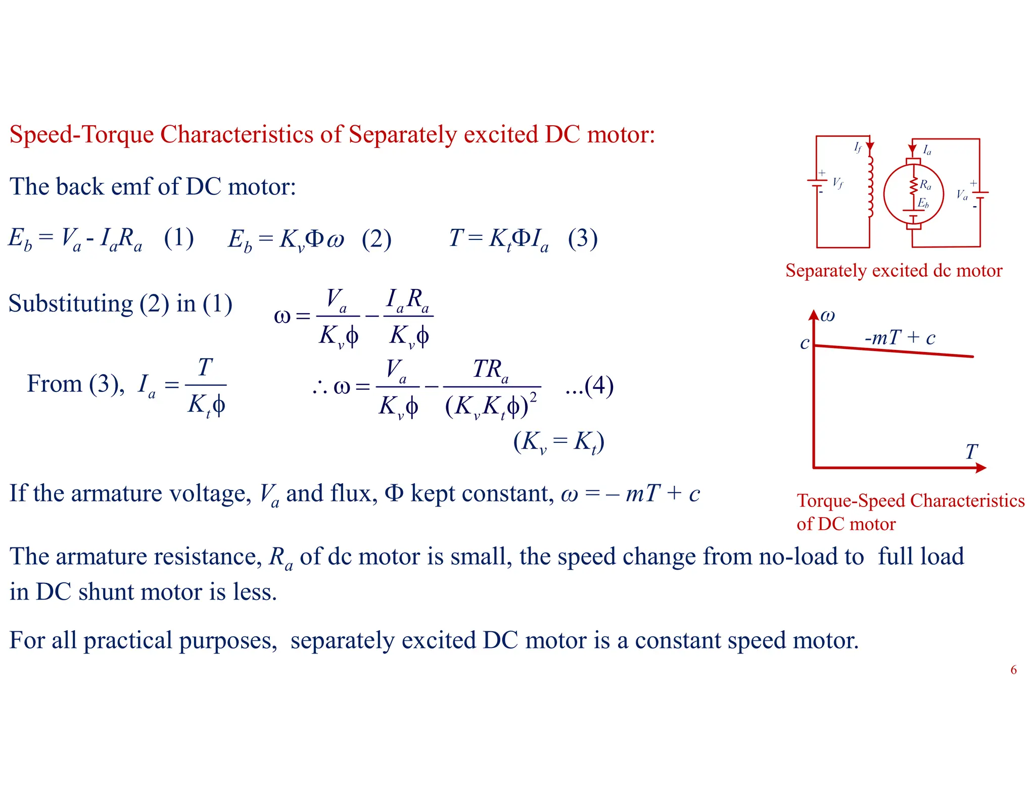
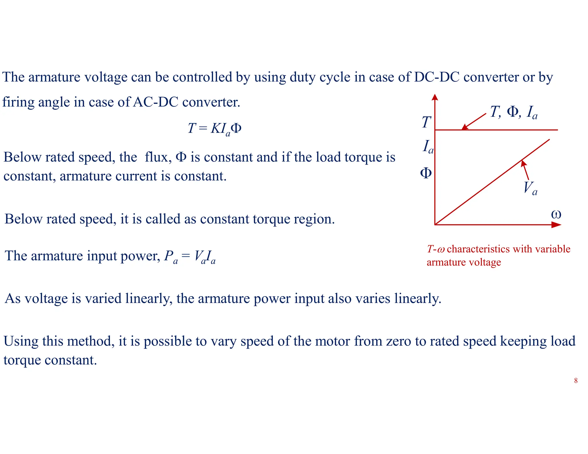
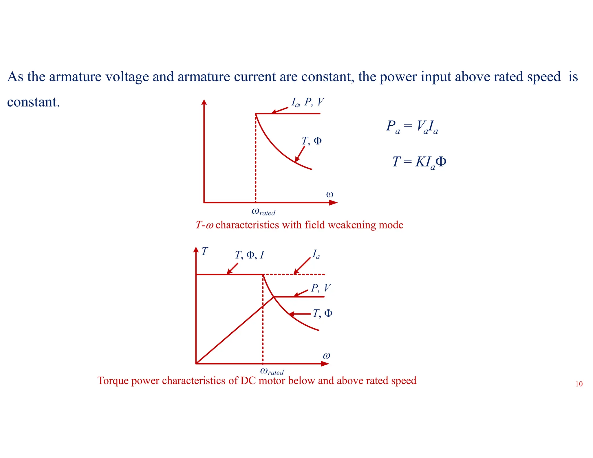
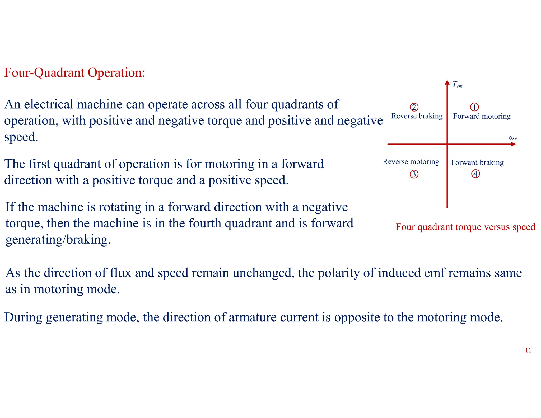
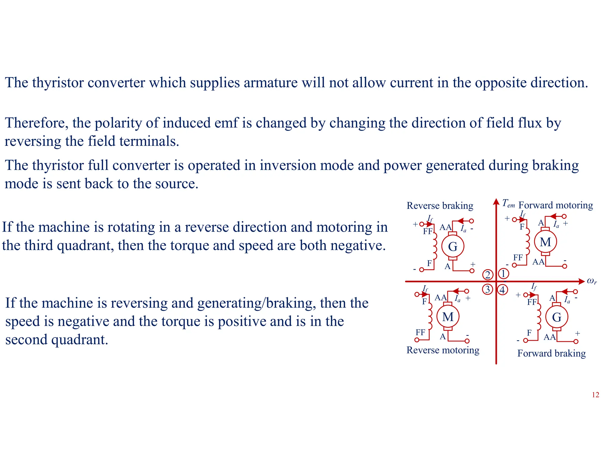
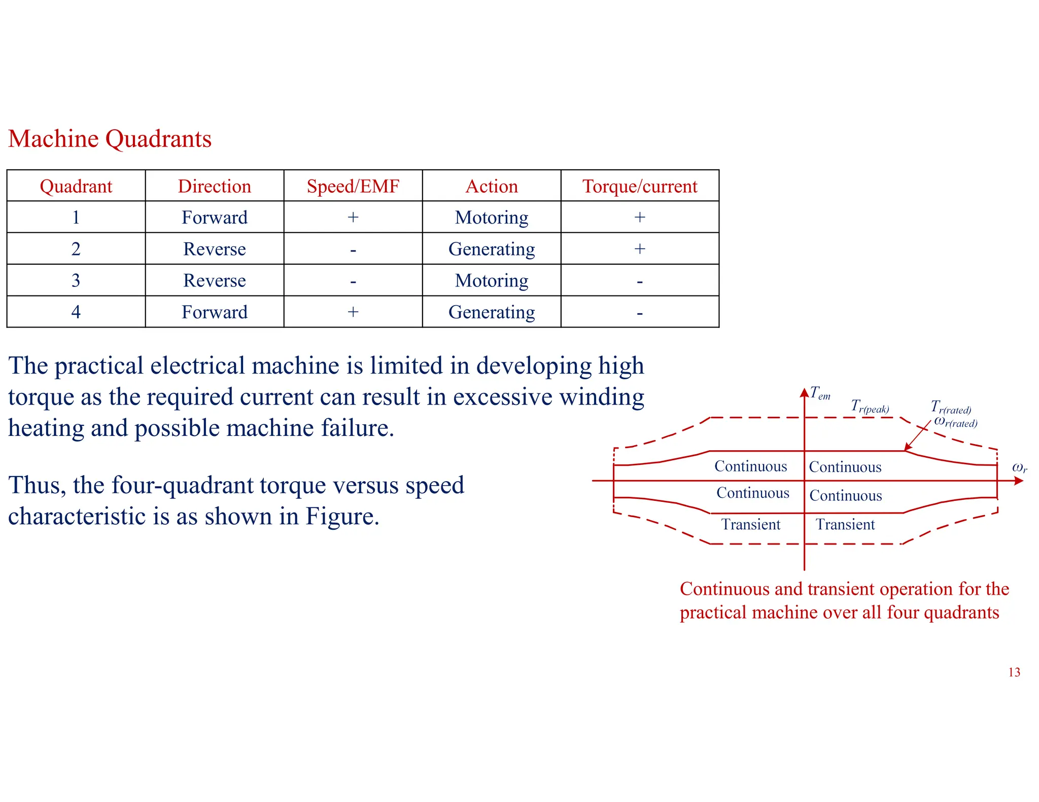
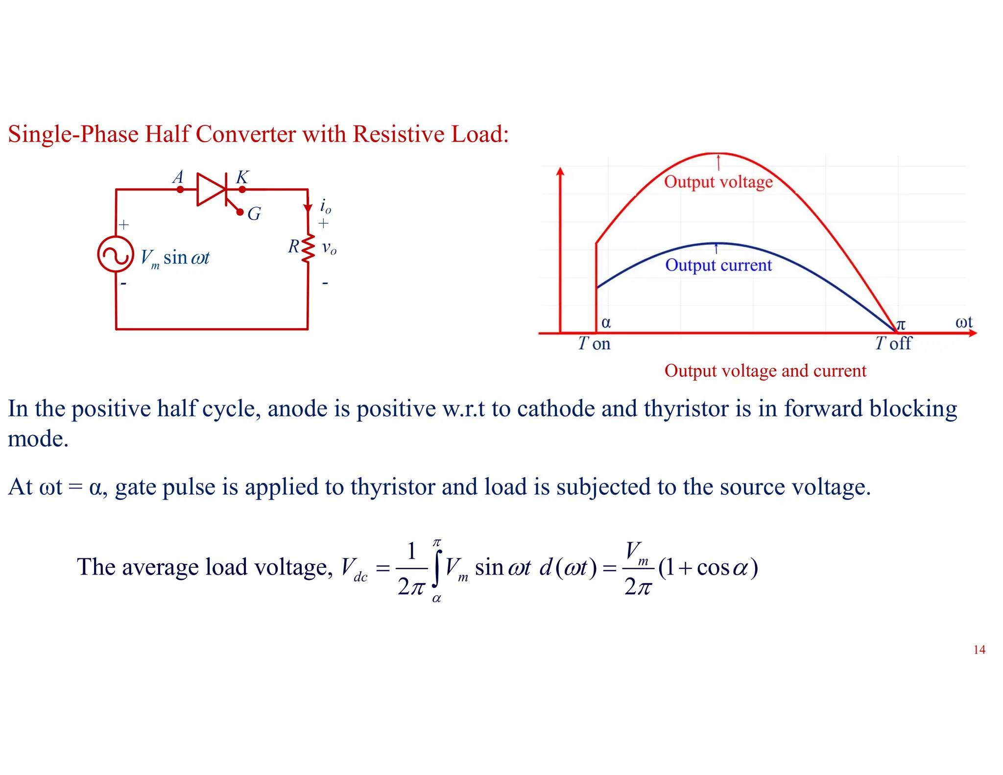
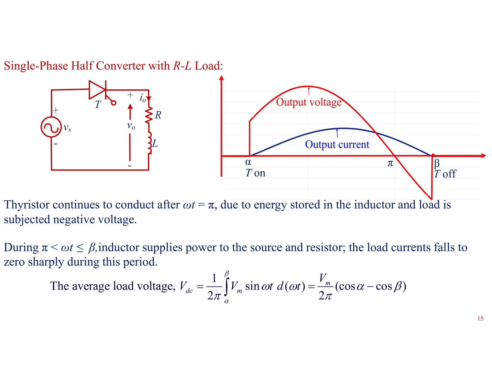
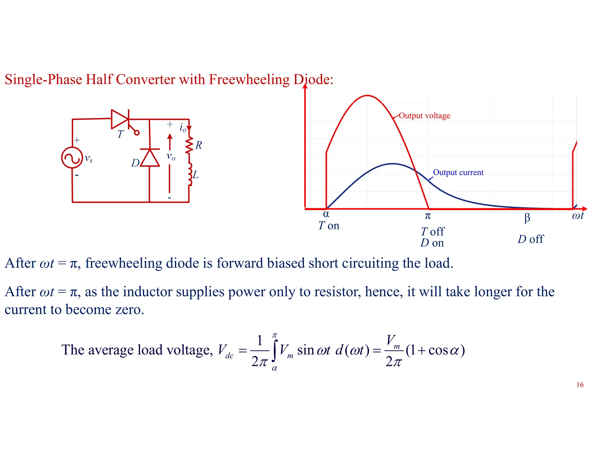
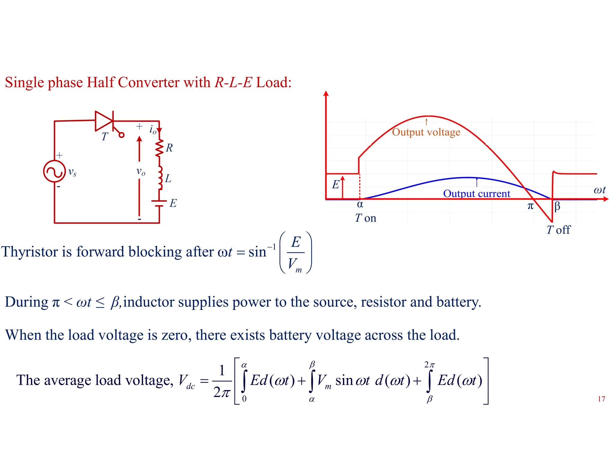
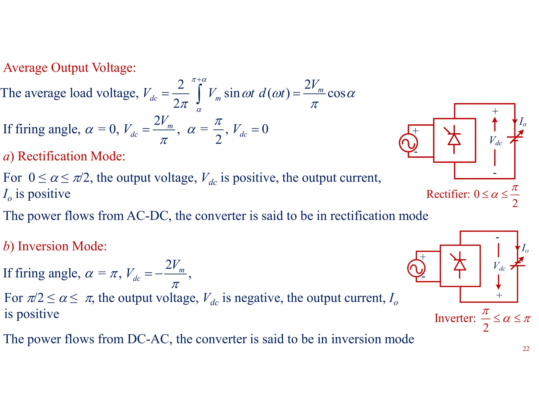
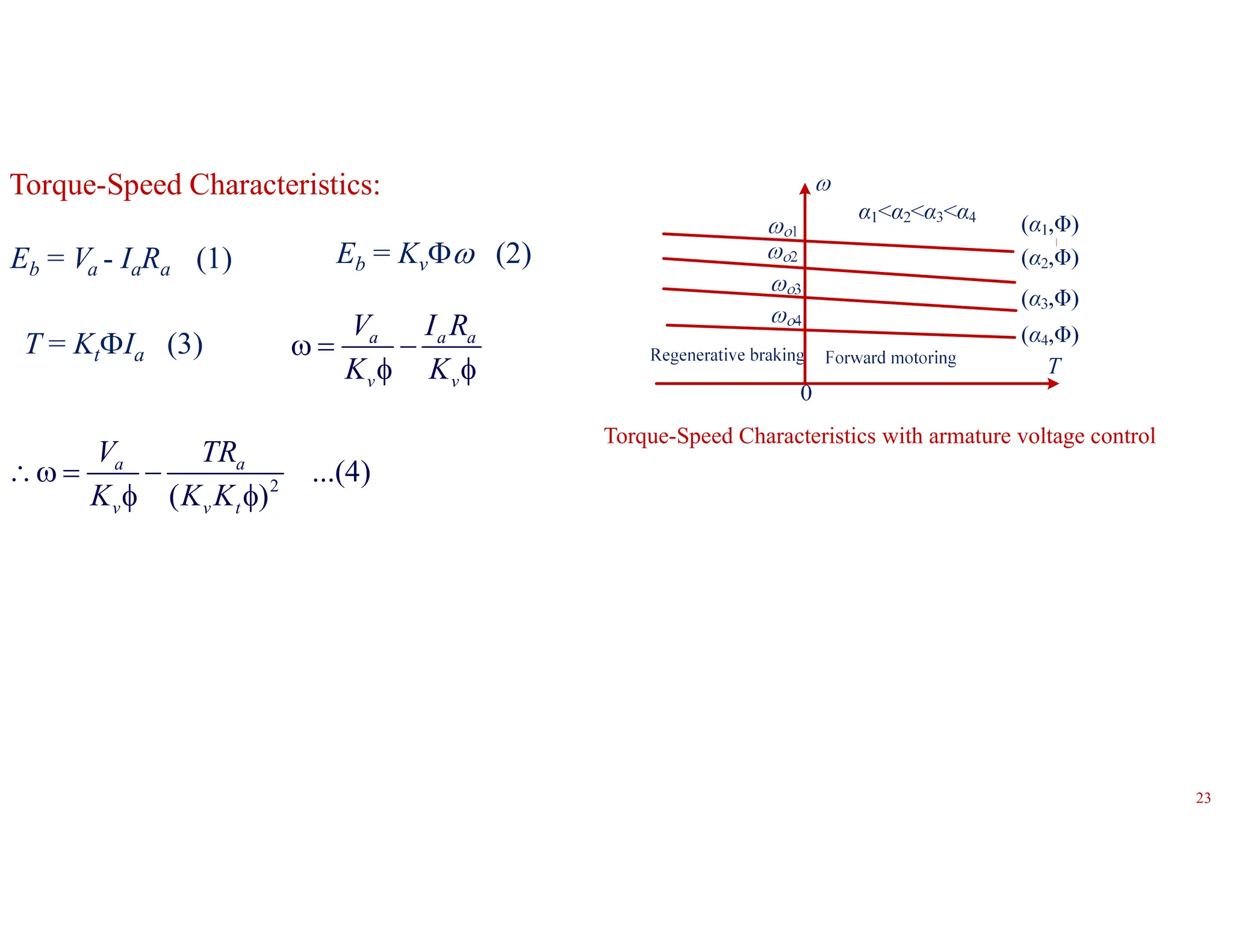
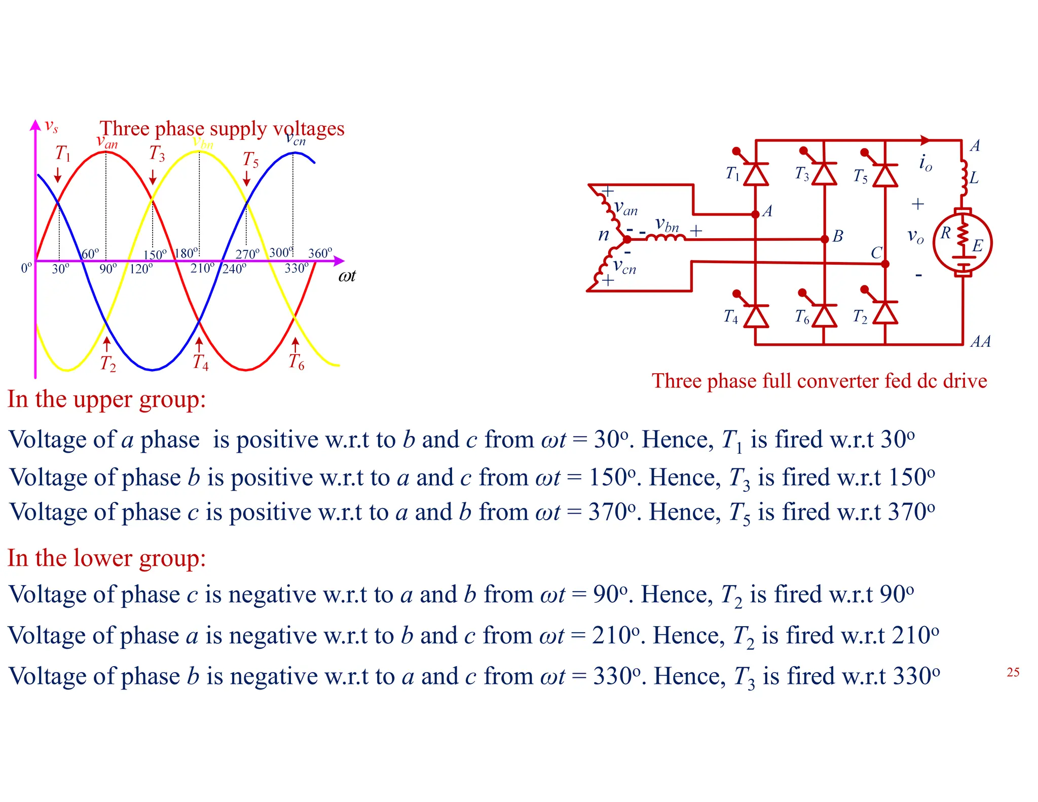
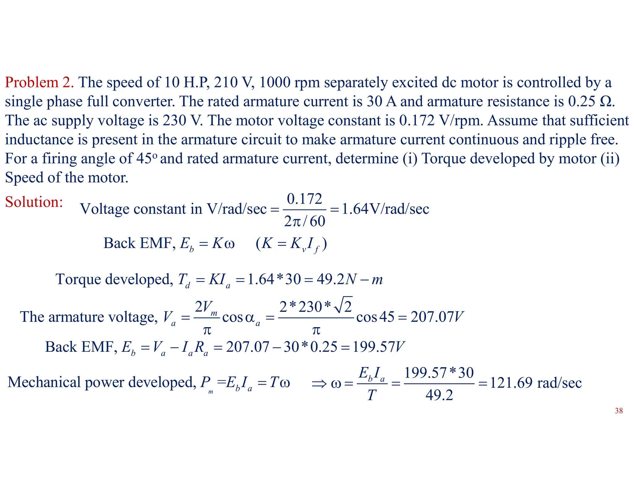
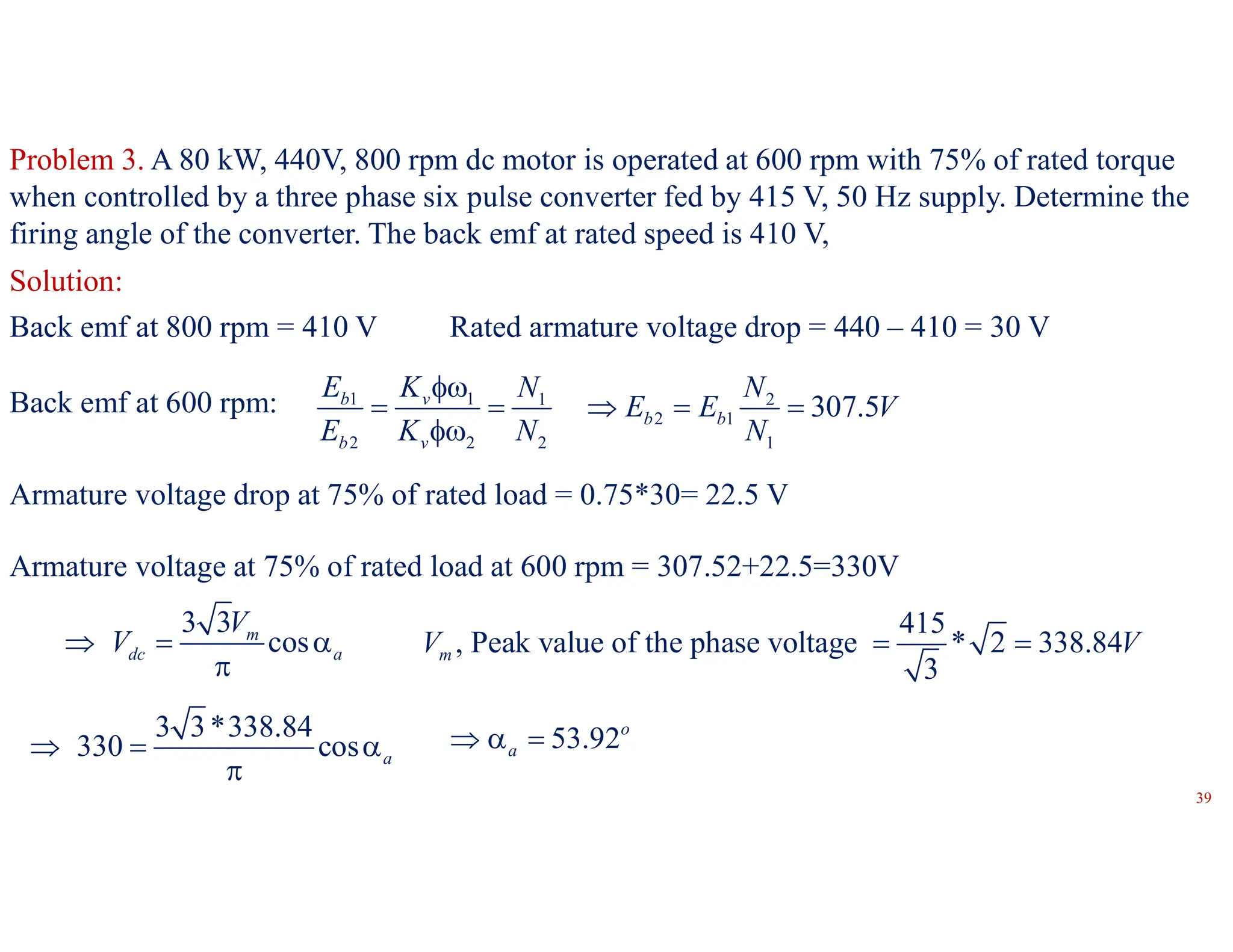
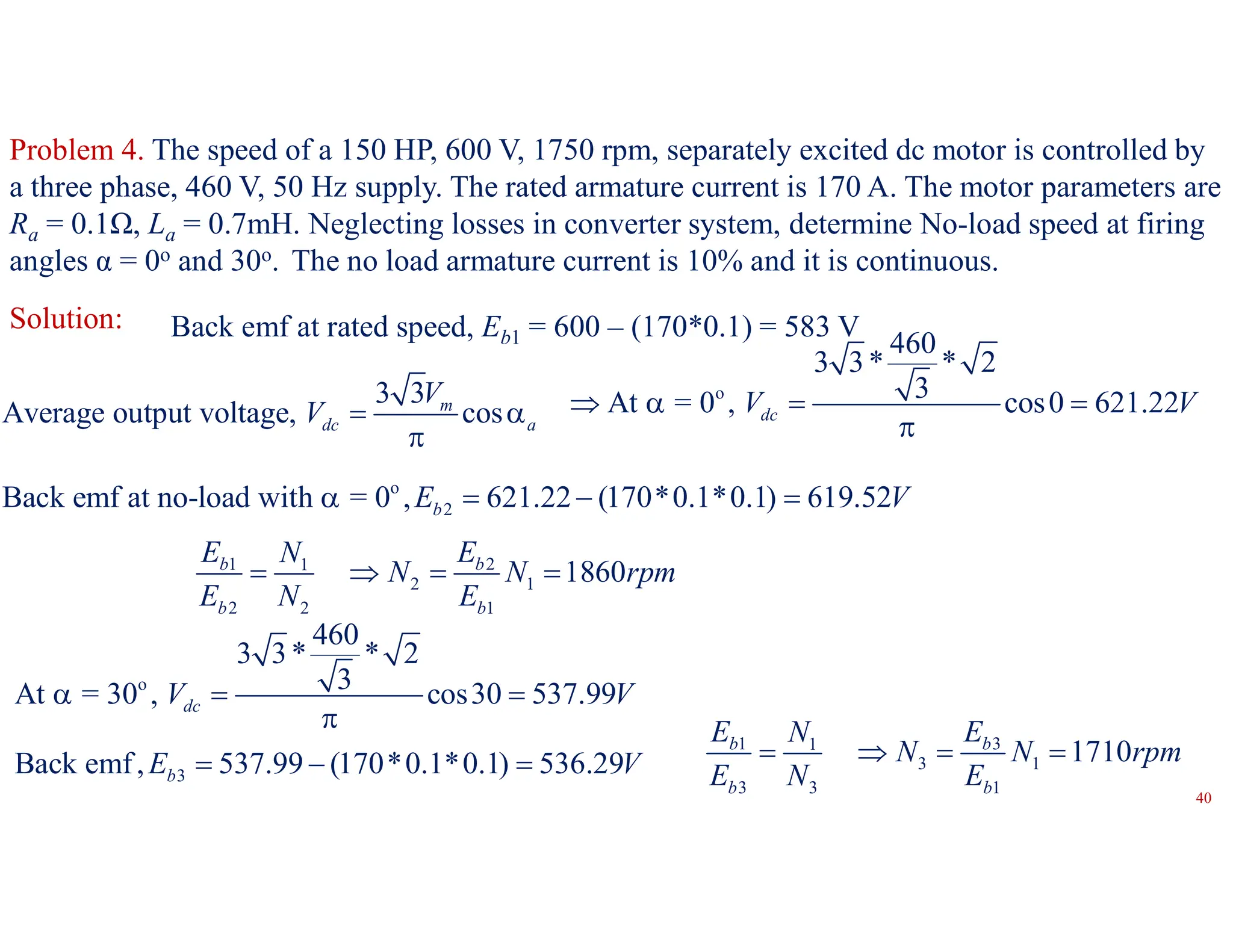
Department of Electrical & Electronics Engineering
Power Semiconductor Drives-A57015
1
Control of DC Motors by Single Phase Converters
DC Motors and their performance characteristics, Four quadrant operation a drive- Introduction
to Thyristor controlled Drives, 1-Φ Semi and Fully controlled converters connected to separately
excited D.C Motor – continuous current operation - Output Voltage and Current waveforms,
Voltage, Speed and Torque expressions, Speed - Torque Characteristics- numerical Problems.
Unit – I:
Control of DC Motors by Three Phase Converters
3-Φ Semi and Fully controlled converters connected to separately excited D.C Motor –
continuous current operation - Output Voltage and Current waveforms, Voltage, Speed and Torque
expressions, Speed - Torque Characteristics- numerical Problems.
The drive employing electric motor is called electric drive
Basic Elements of Electric Drives:
Motion control is required in many industrial and domestic applications like transportation
systems, rolling mills, paper machines, textile mills, such as machine tools, fans, pump, robots,
washing machines, etc.
System employed for motion control is called drive.
The drive may employ prime mover such as diesel/petrol engine, gas/steam turbine, steam
engines, hydraulic motors and electric motors for supplying mechanical energy.
2
Block diagram of a power semiconductor drive
Load is usually a machine to accomplish a task e.g., train, EV, fans, pump, robots, washing
machine, etc.
Usually load requirements are specified with torque-speed demands.
A motor which is capable supplying torque-speed requirement is chosen for the drive.
3
Power converter performs one of the following three functions:
1. Controls the power from source to motor so that required T-N characteristic is obtained.
2. Limits the current during transient operations such as starting, braking, and speed reversals to
avoid damage to the machine.
3. Selects mode of operation i.e., motoring, braking etc.
The motor can be dc motor, induction motor, permanent magnet synchronous motor, BLDC
motor or switched reluctance motor.
The power electronic converter can be a combination of one or more converters.
To match the characteristics of the load with the motor, it is required to sense certain output
quantities such as voltage, current, speed, etc.
Using the measured quantities, the controller generates gate signals for the switching devices.
4
The control algorithm can be implemented in two ways:
1. Analog circuit, by using electronic circuits (not preferred nowadays).
2. Digital circuit, by using microprocessor or digital signal processor.
If the control logic is small, it can be implemented with low cost microprocessor/microcontroller.
If the control algorithm is large, it is implemented with Digital Signal Processor (DSP).
5
Eb = Kv (2)
Speed-Torque Characteristics of Separately excited DC motor:
The back emf of DC motor:
Eb = Va - IaRa (1)
Substituting (2) in (1)
From (3), a
t
T
I
K

 2
...(4)
( )
a a
v v t
V TR
K K K
  
 
a a a
v v
V I R
K K
  
 
If the armature voltage, Va and flux,  kept constant, ω = – mT + c
Separately excited dc motor
Torque-Speed Characteristics
of DC motor
The armature resistance, Ra of dc motor is small, the speed change from no-load to full load
in DC shunt motor is less.
For all practical purposes, separately excited DC motor is a constant speed motor.
T
c -mT + c
ω
(Kv = Kt)
T = KtIa (3)
6
7
Speed Control Below Rated Speed:
In variable speed drive, the speed of the motor is to be changed according to the requirement.
At no-load speed, the torque, TL = T =0
o
The no load speed, = a
V
K


2
Speed of the motor,
( )
a a
V TR
K K
  
 
The speed of the motor can be decreased by reducing armature voltage or increasing flux.
Usually, machine flux is operated at knee point, if flux increased it may reach saturation and
avoided.
Hence, below rated speed, speed is controlled by keeping flux constant and varying the armature
Voltage.
T- characteristics with variable
armature voltage
8
The armature voltage can be controlled by using duty cycle in case of DC-DC converter or by
firing angle in case of AC-DC converter.
T = KIa
Below rated speed, the flux,  is constant and if the load torque is
constant, armature current is constant.
Below rated speed, it is called as constant torque region.
The armature input power, Pa = VaIa
As voltage is varied linearly, the armature power input also varies linearly.
T- characteristics with variable
armature voltage
Using this method, it is possible to vary speed of the motor from zero to rated speed keeping load
torque constant.
9
Speed Control Above Rated Speed:
o
The no-load speed, , a
V
A
K
 

The speed of the motor can be increased either by increasing above the rated voltage or decreasing
the flux.
The armature winding insulation is based on the rated armature voltage.
If the armature voltage is increased above rated, insulation will be damaged.
Hence, above rated speed, armature voltage is kept constant and flux is decreased.
As the speed is increased by decreasing the flux, the load on the armature, should be reduced so
that the armature current does not exceed its rated value.
Therefore, above rated speed, the torque developed is decreased.
10
As the armature voltage and armature current are constant, the power input above rated speed is
constant.
T- characteristics with field weakening mode
Torque power characteristics of DC motor below and above rated speed
Pa = VaIa
T = KIa
11
Four quadrant torque versus speed
Four-Quadrant Operation:
An electrical machine can operate across all four quadrants of
operation, with positive and negative torque and positive and negative
speed.
The first quadrant of operation is for motoring in a forward
direction with a positive torque and a positive speed.
If the machine is rotating in a forward direction with a negative
torque, then the machine is in the fourth quadrant and is forward
generating/braking.
ωr
Tem
Forward motoring
Forward braking
Reverse braking
Reverse motoring
As the direction of flux and speed remain unchanged, the polarity of induced emf remains same
as in motoring mode.
During generating mode, the direction of armature current is opposite to the motoring mode.
If the machine is rotating in a reverse direction and motoring in
the third quadrant, then the torque and speed are both negative.
If the machine is reversing and generating/braking, then the
speed is negative and the torque is positive and is in the
second quadrant.
ωr
Tem Forward motoring
Reverse braking
Forward braking
Reverse motoring
FF
F
A
AA
Ia
G
F
FF
A
AA
Ia
M
-
+
+
-
If
If
+
-
+
-
FF
F
AA
A
Ia
G
If
-
-
+
+
F
FF
AA
A
Ia
M
If
+
-
-
The thyristor converter which supplies armature will not allow current in the opposite direction.
Therefore, the polarity of induced emf is changed by changing the direction of field flux by
reversing the field terminals.
The thyristor full converter is operated in inversion mode and power generated during braking
mode is sent back to the source.
12
13
Continuous and transient operation for the
practical machine over all four quadrants
Quadrant Direction Speed/EMF Action Torque/current
1 Forward + Motoring +
2 Reverse - Generating +
3 Reverse - Motoring -
4 Forward + Generating -
Machine Quadrants
The practical electrical machine is limited in developing high
torque as the required current can result in excessive winding
heating and possible machine failure.
Thus, the four-quadrant torque versus speed
characteristic is as shown in Figure.
sin
m
V t

Single-Phase Half Converter with Resistive Load:
Output voltage and current
In the positive half cycle, anode is positive w.r.t to cathode and thyristor is in forward blocking
mode.
At ωt = α, gate pulse is applied to thyristor and load is subjected to the source voltage.
1
The average load voltage, sin ( ) (1 cos )
2 2
m
dc m
V
V V t d t
  



  
 
14
Single-Phase Half Converter with R-L Load:
π
T on T off
α β
Thyristor continues to conduct after ωt = π, due to energy stored in the inductor and load is
subjected negative voltage.
During π < ωt ≤ β,inductor supplies power to the source and resistor; the load currents falls to
zero sharply during this period.
1
The average load voltage, sin ( ) (cos cos )
2 2
m
dc m
V
V V t d t
  



   
 
15
Single-Phase Half Converter with Freewheeling Diode:
ωt
π
T on
T off
α β
D on D off
After ωt = π, freewheeling diode is forward biased short circuiting the load.
After ωt = π, as the inductor supplies power only to resistor, hence, it will take longer for the
current to become zero.
1
The average load voltage, sin ( ) (1 cos )
2 2
m
dc m
V
V V t d t
  



  
 
16
ωt
π
T on
T off
α β
E
Single phase Half Converter with R-L-E Load:
1
Thyristor is forward blocking after sin
m
E
t
V
  
   
 
During π < ωt ≤ β,inductor supplies power to the source, resistor and battery.
2
0
1
The average load voltage, ( ) sin ( ) ( )
2
dc m
V Ed t V t d t Ed t
 
  
 
 
 
  

 
 
   

When the load voltage is zero, there exists battery voltage across the load.
17
Single-Phase Semi Converter fed DC Motor:
It is one quadrant converter, i.e., output voltage and current are always positive.
Used in industry applications up to 15 kW.
The armature and field are controlled by two separate semi converters.
In the positive half cycle, T1 is in forward
blocking mode and D2 is forward biased.
In the negative half cycle, T2 is in forward
blocking mode and D1 is forward biased.
At ωt = α, gate signal is applied to T1 and the
load is subjected to positive source voltage.
Power flow is unidirectional and always from source to armature.
1
'
T
2
'
D
2
'
T
1
'
D
'
m
D
At ωt = π + α, gate signal is applied to T1 and the load is subjected to positive source
voltage.
18
In continuous current case, the average
load voltage,
2
sin ( ) (1 cos )
2
m
dca m a
V
V V t d t
  



  
 
O
u
t
p
u
t
v
o
l
t
a
g
e
Eb = Kv (2)
Eb = Va - IaRa (1)
2
...(4)
( )
a a
v v t
V TR
K K K
  
 
a a a
v v
V I R
K K
  
 
T = KtIa (3)
Torque-Speed Characteristics:
Torque-Speed Characteristics with constant flux
and reducing armature voltage
19
Single-Phase Full Converter fed DC Motor:
A full converter is a two quadrant converter.
The average output voltage can be either positive or negative.
The output current is always positive.
The converter is used in industry application up to 15 kW.
The armature is excited full converter and field can be excited
by a semi converter
In the positive half cycle, A is positive with respect to B, thyristors, T1,
T2 are in forward blocking mode and turned on at ωt = 
In the negative half cycle, B is positive with respect to A, thyristors, T3, T4 are in forward blocking
mode and turned on at ωt =  + 
20
Vs = 230 V R =0.1, L = 60mH, E = 150 V, α = 30o Vs = 230 V R =0.1, L = 60mH, E = -250 V, α = 150o
a) Rectification mode b) Inversion mode
Output voltage and current waveforms of full converter
21
2
2
The average load voltage, sin ( ) cos
2
m
dc m
V
V V t d t

 

 

  
 
Average Output Voltage:
2
If firing angle, = 0, ,
m
dc
V
V 


For 0 ≤  ≤ /2, the output voltage, Vdc is positive, the output current,
Io is positive
Vdc
+
-
+
-
Io
Rectifier: 0
2
 


a) Rectification Mode:
The power flows from AC-DC, the converter is said to be in rectification mode
= , 0
2
dc
V 


b) Inversion Mode:
2
If firing angle, = , ,
m
dc
V
V  
 

For /2 ≤  ≤ , the output voltage, Vdc is negative, the output current, Io
is positive Inverter:
2
 

 
The power flows from DC-AC, the converter is said to be in inversion mode
22
Eb = Kv (2)
Eb = Va - IaRa (1)
2
...(4)
( )
a a
v v t
V TR
K K K
  
 
a a a
v v
V I R
K K
  
 
T = KtIa (3)
Torque-Speed Characteristics:
Torque-Speed Characteristics with armature voltage control
23
Three Phase Rectifiers provide higher average output voltage.
Ripple frequency is more compared to single phase converters.
Ripple frequency in single phase full converter is 2fs
Ripple frequency in three phase full converter is 6fs
The ripple in the load current can be reduced by connecting an inductor in series with the load.
The ripple in the load voltage can be reduced by connecting a capacitor in parallel to the load.
Hence, filtering requirement is less: The size of inductor and capacitor will be less
Three phase Fully Controlled fed DC Motor:
24
Voltage of a phase is positive w.r.t to b and c from ωt = 30o. Hence, T1 is fired w.r.t 30o
Voltage of phase b is positive w.r.t to a and c from ωt = 150o. Hence, T3 is fired w.r.t 150o
Voltage of phase c is positive w.r.t to a and b from ωt = 370o. Hence, T5 is fired w.r.t 370o
In the upper group:
Voltage of phase c is negative w.r.t to a and b from ωt = 90o. Hence, T2 is fired w.r.t 90o
Voltage of phase a is negative w.r.t to b and c from ωt = 210o. Hence, T2 is fired w.r.t 210o
Voltage of phase b is negative w.r.t to a and c from ωt = 330o. Hence, T3 is fired w.r.t 330o
In the lower group:
Three phase full converter fed dc drive
Three phase supply voltages
t

25
For every 60o, one thyristor is turned on
Each thyristor conducts for a duration of 120o
At any instant, two thyristors conduct, one from upper group and one from lower group
For a period of 2, there are 6 pulses in the output voltage, also called as 6-pulse converter
Turning on one thyristor will turn off existing thyristor of same group due to natural
commutation.
For ex: If T1 is turned on, T5 is turned off in the upper group.
In the lower group, when T2 is turned on, T6 is turned off.
26
Firing angle,  = 30o :
T1  30o + 30o = 60o
Assume that T6 already conducting in the lower
group
Applying KVL, -van + vo + vbn = 0  vo = van – vbn = vab
The load is subjected to line voltage of vab
T2 is turned on at 90o+ 30o = 120o
From ωt = 60o, T1 in the upper group and T6 in the lower
group conduct
T4  240o T6  360o
Similarly, T3  180o T5  300o
27
Phasor diagram
sin
an m
v V t
 
3 sin( 30 )
o
ab an bn m
v v v V t
   

sin( 120 )
o
cn m
v V t
 

sin( 120 )
o
bn m
v V t
 

0
60
0
30
0
90
0
120 0
150 0
180
0
210 0
240 0
270 0
300 0
330
0
0
t

0
360
t

3 m
V
a) Phase voltage, van b) Line voltage, vab
28
Vs = 400 V (L-L) R =0.25, L = 50mH, E = 410 V, α = 0o
Vs = 400 V (L-L) R =0.25, L = 50mH, E = 410 V, α = 30o
Vs = 400 V (L-L) R =0.25, L = 50mH, E = -500 V, α = 150o
29
Average DC Output Voltage:
For a period of 360o (from 30o +  to 330o + ), there are six identical pulses
During 30o +  to 90o + , T1 T6 are on, vo = vab
2
6
3 3
6
The average DC voltage, 3 sin( ) ( ) cos
2 6
m
dc m
V
V V t d t


  






  
 
For 0 ≤  < 90o, Vdc is positive and Io is positive, power flows
from AC-DC, the converter is in rectification mode,
Vdc
+
-
+
-
Io
Rectifier
o
For = 0 ,
3 3 m
dc
V
V 


o
= 90 , 0
dc
V 

30
For 90 <  ≤ 180o, Vdc is negative and Io is positive, power flows from
DC-AC, the converter is in inversion mode Inverter
3 3
For 180 ,
o m
dc
V
V
  


o
= 0 , 0
dc
V 

Eb = Kv (2)
Eb = Va - IaRa (1)
2
...(5)
( )
a a
v v t
V TR
K K K
  
 
(3)
a a a
v v
V I R
K K
  
 
T = KtIa (4)
Torque-Speed Characteristics:
Torque-Speed Characteristics with constant flux and reducing
armature voltage
From (1) and (2)
From (3) and (4)
31
Three phase Semi-Converter fed DC Motor:
Three phase semi-converters are used in industry applications up to 120 kW, where one quadrant
operation is required.
Three phase semi converter fed dc drive
32
Voltage of a phase is positive w.r.t to b and c from ωt = 30o.
Hence, T1 is fired w.r.t 30o
Voltage of phase b is positive w.r.t to a and c from ωt = 150o.
Hence, T2 is fired w.r.t 150o
Voltage of phase c is positive w.r.t to a and b from ωt = 370o.
Hence, T5 is fired w.r.t 370o
Voltage of phase c is negative w.r.t to a and b from ωt = 90o. Hence, D2 is forward biased from
90o
Voltage of phase a is negative w.r.t to b and c from ωt = 210o. Hence, D4 is forward biased from
210o
Voltage of phase b is negative w.r.t to a and c from ωt = 330o. Hence, D6 is forward biased from
330o
t

33
Vs = 400 V (L-L) R =0.25, L = 50mH, E = 410 V, α = 0o Vs = 400 V (L-L) R =0.25, L = 50mH, E = 410 V, α = 30o
Average DC Output Voltage:
2 2
6 6
3 3
3 3
( ) 3 sin( ) ( ) (1 cos )
2 2 6 2
m
dc ac m
V
V v d t V t d t
 
 
    
 
 
 
 
 

   
  
For >30o, the output voltage becomes discontinous
For ≤30o, the average output voltage can be given as
34
Eb = Kv (2)
Eb = Va - IaRa (1)
2
...(4)
( )
a a
v v t
V TR
K K K
  
 
a a a
v v
V I R
K K
  
 
T = KtIa (3)
Torque-Speed Characteristics:
Torque-Speed with armature voltage control
35
Problem 1. A separately excited DC motor is fed from a 230 V 50 Hz supply through a single
phase half controlled bridge rectifier. Armature parameters are: L = 0.06 H and R = 0.3 Ω. The
motor voltage constant is Ka = 0.9 V/A-rad/sec and the field resistance is 104Ω. Field current is
also controlled by semi converter and is set to maximum possible value. The load torque is 50 N-
m at 800 rpm. The inductances of the armature and field circuits are sufficiently enough to make
the armature and field current continuous and ripple free. Compute (i) Field current (ii) The firing
angle of the converter in the armature circuit.
Solution:
230* 2
The field voltage, (1 cos ) (1 cos0 ) 207.07
o
m
f f
V
V V
     
 
207.07
The field current, 1.99
104
f
f
f
V
I A
R
  
207.07
The field current, 1.99
104
f
f
f
V
I A
R
  
(i) Field current:
36
2
Back EMF, 0.9*1.99* 800 150.04
60
b v f
E K I V

   
Torque developed, d t f a
T K I I

50
Armature current, 27.92
0.9*1.99
d
a
t f
T
I A
K I
  
Armature voltage, 150 27.92*0.3 158.37
a b a a
V E I R V
    
Also, the armature voltage, (1 cos )
m
a a
V
V   

230* 2
158.37 (1 cos )
a
   

cos 58.7o
a
  
(ii) Firing angle of armature converter:
(In a dc motor, )
v t
K K

37
Problem 2. The speed of 10 H.P, 210 V, 1000 rpm separately excited dc motor is controlled by a
single phase full converter. The rated armature current is 30 A and armature resistance is 0.25 Ω.
The ac supply voltage is 230 V. The motor voltage constant is 0.172 V/rpm. Assume that sufficient
inductance is present in the armature circuit to make armature current continuous and ripple free.
For a firing angle of 45o and rated armature current, determine (i) Torque developed by motor (ii)
Speed of the motor.
0.172
Voltage constant in V/rad/sec 1.64V/rad/sec
2 /60
 

Solution:
Torque developed, 1.64*30 49.2
d a
T KI N m
   
Back EMF, ( )
b v f
E K K K I
  
Back EMF, 207.07 30*0.25 199.57
b a a a
E V I R V
    
2 2*230* 2
The armature voltage, cos cos45 207.07
m
a a
V
V V
   
 
Mechanical power developed, =
m b a
P E I T
 
199.57*30
121.69 rad/sec
49.2
b a
E I
T
    
38
Problem 3. A 80 kW, 440V, 800 rpm dc motor is operated at 600 rpm with 75% of rated torque
when controlled by a three phase six pulse converter fed by 415 V, 50 Hz supply. Determine the
firing angle of the converter. The back emf at rated speed is 410 V,
Solution:
Back emf at 800 rpm = 410 V Rated armature voltage drop = 440 – 410 = 30 V
Back emf at 600 rpm: 1 1 1 2
2 1
2 2 2 1
307.5
b v
b b
b v
E K N N
E E V
E K N N

    

Armature voltage drop at 75% of rated load = 0.75*30= 22.5 V
Armature voltage at 75% of rated load at 600 rpm = 307.52+22.5=330V
3 3
cos
m
dc a
V
V
  

415
, Peak value of the phase voltage * 2 338.84
3
m
V V
 
3 3*338.84
330 cos a
  

53.92o
a
  
39
Problem 4. The speed of a 150 HP, 600 V, 1750 rpm, separately excited dc motor is controlled by
a three phase, 460 V, 50 Hz supply. The rated armature current is 170 A. The motor parameters are
Ra = 0.1Ω, La = 0.7mH. Neglecting losses in converter system, determine No-load speed at firing
angles α = 0o and 30o. The no load armature current is 10% and it is continuous.
Solution: Back emf at rated speed, Eb1 = 600 – (170*0.1) = 583 V
3 3
Average output voltage, cos
m
dc a
V
V  

o
460
3 3* * 2
3
At = 0 , cos0 621.22
dc
V V
   

o
2
Back emf at no-load with = 0 , 621.22 (170*0.1*0.1) 619.52
b
E V
   
1 2
1
2 1
2 2 1
1860
b b
b b
E E
N
N N rpm
E N E
   
o
460
3 3* * 2
3
At = 30 , cos30 537.99
dc
V V
  

3
Back emf, 537.99 (170*0.1*0.1) 536.29
b
E V
  
1 3
1
3 1
3 3 1
1710
b b
b b
E E
N
N N rpm
E N E
   
40
41

Control of DC Motors by Single Phase Converters.pdf

  • 1.
    Department of Electrical& Electronics Engineering Power Semiconductor Drives-A57015 1 Control of DC Motors by Single Phase Converters DC Motors and their performance characteristics, Four quadrant operation a drive- Introduction to Thyristor controlled Drives, 1-Φ Semi and Fully controlled converters connected to separately excited D.C Motor – continuous current operation - Output Voltage and Current waveforms, Voltage, Speed and Torque expressions, Speed - Torque Characteristics- numerical Problems. Unit – I: Control of DC Motors by Three Phase Converters 3-Φ Semi and Fully controlled converters connected to separately excited D.C Motor – continuous current operation - Output Voltage and Current waveforms, Voltage, Speed and Torque expressions, Speed - Torque Characteristics- numerical Problems.
  • 2.
    The drive employingelectric motor is called electric drive Basic Elements of Electric Drives: Motion control is required in many industrial and domestic applications like transportation systems, rolling mills, paper machines, textile mills, such as machine tools, fans, pump, robots, washing machines, etc. System employed for motion control is called drive. The drive may employ prime mover such as diesel/petrol engine, gas/steam turbine, steam engines, hydraulic motors and electric motors for supplying mechanical energy. 2
  • 3.
    Block diagram ofa power semiconductor drive Load is usually a machine to accomplish a task e.g., train, EV, fans, pump, robots, washing machine, etc. Usually load requirements are specified with torque-speed demands. A motor which is capable supplying torque-speed requirement is chosen for the drive. 3
  • 4.
    Power converter performsone of the following three functions: 1. Controls the power from source to motor so that required T-N characteristic is obtained. 2. Limits the current during transient operations such as starting, braking, and speed reversals to avoid damage to the machine. 3. Selects mode of operation i.e., motoring, braking etc. The motor can be dc motor, induction motor, permanent magnet synchronous motor, BLDC motor or switched reluctance motor. The power electronic converter can be a combination of one or more converters. To match the characteristics of the load with the motor, it is required to sense certain output quantities such as voltage, current, speed, etc. Using the measured quantities, the controller generates gate signals for the switching devices. 4
  • 5.
    The control algorithmcan be implemented in two ways: 1. Analog circuit, by using electronic circuits (not preferred nowadays). 2. Digital circuit, by using microprocessor or digital signal processor. If the control logic is small, it can be implemented with low cost microprocessor/microcontroller. If the control algorithm is large, it is implemented with Digital Signal Processor (DSP). 5
  • 6.
    Eb = Kv(2) Speed-Torque Characteristics of Separately excited DC motor: The back emf of DC motor: Eb = Va - IaRa (1) Substituting (2) in (1) From (3), a t T I K   2 ...(4) ( ) a a v v t V TR K K K      a a a v v V I R K K      If the armature voltage, Va and flux,  kept constant, ω = – mT + c Separately excited dc motor Torque-Speed Characteristics of DC motor The armature resistance, Ra of dc motor is small, the speed change from no-load to full load in DC shunt motor is less. For all practical purposes, separately excited DC motor is a constant speed motor. T c -mT + c ω (Kv = Kt) T = KtIa (3) 6
  • 7.
    7 Speed Control BelowRated Speed: In variable speed drive, the speed of the motor is to be changed according to the requirement. At no-load speed, the torque, TL = T =0 o The no load speed, = a V K   2 Speed of the motor, ( ) a a V TR K K      The speed of the motor can be decreased by reducing armature voltage or increasing flux. Usually, machine flux is operated at knee point, if flux increased it may reach saturation and avoided. Hence, below rated speed, speed is controlled by keeping flux constant and varying the armature Voltage. T- characteristics with variable armature voltage
  • 8.
    8 The armature voltagecan be controlled by using duty cycle in case of DC-DC converter or by firing angle in case of AC-DC converter. T = KIa Below rated speed, the flux,  is constant and if the load torque is constant, armature current is constant. Below rated speed, it is called as constant torque region. The armature input power, Pa = VaIa As voltage is varied linearly, the armature power input also varies linearly. T- characteristics with variable armature voltage Using this method, it is possible to vary speed of the motor from zero to rated speed keeping load torque constant.
  • 9.
    9 Speed Control AboveRated Speed: o The no-load speed, , a V A K    The speed of the motor can be increased either by increasing above the rated voltage or decreasing the flux. The armature winding insulation is based on the rated armature voltage. If the armature voltage is increased above rated, insulation will be damaged. Hence, above rated speed, armature voltage is kept constant and flux is decreased. As the speed is increased by decreasing the flux, the load on the armature, should be reduced so that the armature current does not exceed its rated value. Therefore, above rated speed, the torque developed is decreased.
  • 10.
    10 As the armaturevoltage and armature current are constant, the power input above rated speed is constant. T- characteristics with field weakening mode Torque power characteristics of DC motor below and above rated speed Pa = VaIa T = KIa
  • 11.
    11 Four quadrant torqueversus speed Four-Quadrant Operation: An electrical machine can operate across all four quadrants of operation, with positive and negative torque and positive and negative speed. The first quadrant of operation is for motoring in a forward direction with a positive torque and a positive speed. If the machine is rotating in a forward direction with a negative torque, then the machine is in the fourth quadrant and is forward generating/braking. ωr Tem Forward motoring Forward braking Reverse braking Reverse motoring As the direction of flux and speed remain unchanged, the polarity of induced emf remains same as in motoring mode. During generating mode, the direction of armature current is opposite to the motoring mode.
  • 12.
    If the machineis rotating in a reverse direction and motoring in the third quadrant, then the torque and speed are both negative. If the machine is reversing and generating/braking, then the speed is negative and the torque is positive and is in the second quadrant. ωr Tem Forward motoring Reverse braking Forward braking Reverse motoring FF F A AA Ia G F FF A AA Ia M - + + - If If + - + - FF F AA A Ia G If - - + + F FF AA A Ia M If + - - The thyristor converter which supplies armature will not allow current in the opposite direction. Therefore, the polarity of induced emf is changed by changing the direction of field flux by reversing the field terminals. The thyristor full converter is operated in inversion mode and power generated during braking mode is sent back to the source. 12
  • 13.
    13 Continuous and transientoperation for the practical machine over all four quadrants Quadrant Direction Speed/EMF Action Torque/current 1 Forward + Motoring + 2 Reverse - Generating + 3 Reverse - Motoring - 4 Forward + Generating - Machine Quadrants The practical electrical machine is limited in developing high torque as the required current can result in excessive winding heating and possible machine failure. Thus, the four-quadrant torque versus speed characteristic is as shown in Figure.
  • 14.
    sin m V t  Single-Phase HalfConverter with Resistive Load: Output voltage and current In the positive half cycle, anode is positive w.r.t to cathode and thyristor is in forward blocking mode. At ωt = α, gate pulse is applied to thyristor and load is subjected to the source voltage. 1 The average load voltage, sin ( ) (1 cos ) 2 2 m dc m V V V t d t            14
  • 15.
    Single-Phase Half Converterwith R-L Load: π T on T off α β Thyristor continues to conduct after ωt = π, due to energy stored in the inductor and load is subjected negative voltage. During π < ωt ≤ β,inductor supplies power to the source and resistor; the load currents falls to zero sharply during this period. 1 The average load voltage, sin ( ) (cos cos ) 2 2 m dc m V V V t d t             15
  • 16.
    Single-Phase Half Converterwith Freewheeling Diode: ωt π T on T off α β D on D off After ωt = π, freewheeling diode is forward biased short circuiting the load. After ωt = π, as the inductor supplies power only to resistor, hence, it will take longer for the current to become zero. 1 The average load voltage, sin ( ) (1 cos ) 2 2 m dc m V V V t d t            16
  • 17.
    ωt π T on T off αβ E Single phase Half Converter with R-L-E Load: 1 Thyristor is forward blocking after sin m E t V          During π < ωt ≤ β,inductor supplies power to the source, resistor and battery. 2 0 1 The average load voltage, ( ) sin ( ) ( ) 2 dc m V Ed t V t d t Ed t                         When the load voltage is zero, there exists battery voltage across the load. 17
  • 18.
    Single-Phase Semi Converterfed DC Motor: It is one quadrant converter, i.e., output voltage and current are always positive. Used in industry applications up to 15 kW. The armature and field are controlled by two separate semi converters. In the positive half cycle, T1 is in forward blocking mode and D2 is forward biased. In the negative half cycle, T2 is in forward blocking mode and D1 is forward biased. At ωt = α, gate signal is applied to T1 and the load is subjected to positive source voltage. Power flow is unidirectional and always from source to armature. 1 ' T 2 ' D 2 ' T 1 ' D ' m D At ωt = π + α, gate signal is applied to T1 and the load is subjected to positive source voltage. 18
  • 19.
    In continuous currentcase, the average load voltage, 2 sin ( ) (1 cos ) 2 m dca m a V V V t d t            O u t p u t v o l t a g e Eb = Kv (2) Eb = Va - IaRa (1) 2 ...(4) ( ) a a v v t V TR K K K      a a a v v V I R K K      T = KtIa (3) Torque-Speed Characteristics: Torque-Speed Characteristics with constant flux and reducing armature voltage 19
  • 20.
    Single-Phase Full Converterfed DC Motor: A full converter is a two quadrant converter. The average output voltage can be either positive or negative. The output current is always positive. The converter is used in industry application up to 15 kW. The armature is excited full converter and field can be excited by a semi converter In the positive half cycle, A is positive with respect to B, thyristors, T1, T2 are in forward blocking mode and turned on at ωt =  In the negative half cycle, B is positive with respect to A, thyristors, T3, T4 are in forward blocking mode and turned on at ωt =  +  20
  • 21.
    Vs = 230V R =0.1, L = 60mH, E = 150 V, α = 30o Vs = 230 V R =0.1, L = 60mH, E = -250 V, α = 150o a) Rectification mode b) Inversion mode Output voltage and current waveforms of full converter 21
  • 22.
    2 2 The average loadvoltage, sin ( ) cos 2 m dc m V V V t d t             Average Output Voltage: 2 If firing angle, = 0, , m dc V V    For 0 ≤  ≤ /2, the output voltage, Vdc is positive, the output current, Io is positive Vdc + - + - Io Rectifier: 0 2     a) Rectification Mode: The power flows from AC-DC, the converter is said to be in rectification mode = , 0 2 dc V    b) Inversion Mode: 2 If firing angle, = , , m dc V V      For /2 ≤  ≤ , the output voltage, Vdc is negative, the output current, Io is positive Inverter: 2      The power flows from DC-AC, the converter is said to be in inversion mode 22
  • 23.
    Eb = Kv(2) Eb = Va - IaRa (1) 2 ...(4) ( ) a a v v t V TR K K K      a a a v v V I R K K      T = KtIa (3) Torque-Speed Characteristics: Torque-Speed Characteristics with armature voltage control 23
  • 24.
    Three Phase Rectifiersprovide higher average output voltage. Ripple frequency is more compared to single phase converters. Ripple frequency in single phase full converter is 2fs Ripple frequency in three phase full converter is 6fs The ripple in the load current can be reduced by connecting an inductor in series with the load. The ripple in the load voltage can be reduced by connecting a capacitor in parallel to the load. Hence, filtering requirement is less: The size of inductor and capacitor will be less Three phase Fully Controlled fed DC Motor: 24
  • 25.
    Voltage of aphase is positive w.r.t to b and c from ωt = 30o. Hence, T1 is fired w.r.t 30o Voltage of phase b is positive w.r.t to a and c from ωt = 150o. Hence, T3 is fired w.r.t 150o Voltage of phase c is positive w.r.t to a and b from ωt = 370o. Hence, T5 is fired w.r.t 370o In the upper group: Voltage of phase c is negative w.r.t to a and b from ωt = 90o. Hence, T2 is fired w.r.t 90o Voltage of phase a is negative w.r.t to b and c from ωt = 210o. Hence, T2 is fired w.r.t 210o Voltage of phase b is negative w.r.t to a and c from ωt = 330o. Hence, T3 is fired w.r.t 330o In the lower group: Three phase full converter fed dc drive Three phase supply voltages t  25
  • 26.
    For every 60o,one thyristor is turned on Each thyristor conducts for a duration of 120o At any instant, two thyristors conduct, one from upper group and one from lower group For a period of 2, there are 6 pulses in the output voltage, also called as 6-pulse converter Turning on one thyristor will turn off existing thyristor of same group due to natural commutation. For ex: If T1 is turned on, T5 is turned off in the upper group. In the lower group, when T2 is turned on, T6 is turned off. 26
  • 27.
    Firing angle, = 30o : T1  30o + 30o = 60o Assume that T6 already conducting in the lower group Applying KVL, -van + vo + vbn = 0  vo = van – vbn = vab The load is subjected to line voltage of vab T2 is turned on at 90o+ 30o = 120o From ωt = 60o, T1 in the upper group and T6 in the lower group conduct T4  240o T6  360o Similarly, T3  180o T5  300o 27
  • 28.
    Phasor diagram sin an m vV t   3 sin( 30 ) o ab an bn m v v v V t      sin( 120 ) o cn m v V t    sin( 120 ) o bn m v V t    0 60 0 30 0 90 0 120 0 150 0 180 0 210 0 240 0 270 0 300 0 330 0 0 t  0 360 t  3 m V a) Phase voltage, van b) Line voltage, vab 28
  • 29.
    Vs = 400V (L-L) R =0.25, L = 50mH, E = 410 V, α = 0o Vs = 400 V (L-L) R =0.25, L = 50mH, E = 410 V, α = 30o Vs = 400 V (L-L) R =0.25, L = 50mH, E = -500 V, α = 150o 29
  • 30.
    Average DC OutputVoltage: For a period of 360o (from 30o +  to 330o + ), there are six identical pulses During 30o +  to 90o + , T1 T6 are on, vo = vab 2 6 3 3 6 The average DC voltage, 3 sin( ) ( ) cos 2 6 m dc m V V V t d t                 For 0 ≤  < 90o, Vdc is positive and Io is positive, power flows from AC-DC, the converter is in rectification mode, Vdc + - + - Io Rectifier o For = 0 , 3 3 m dc V V    o = 90 , 0 dc V   30
  • 31.
    For 90 < ≤ 180o, Vdc is negative and Io is positive, power flows from DC-AC, the converter is in inversion mode Inverter 3 3 For 180 , o m dc V V      o = 0 , 0 dc V   Eb = Kv (2) Eb = Va - IaRa (1) 2 ...(5) ( ) a a v v t V TR K K K      (3) a a a v v V I R K K      T = KtIa (4) Torque-Speed Characteristics: Torque-Speed Characteristics with constant flux and reducing armature voltage From (1) and (2) From (3) and (4) 31
  • 32.
    Three phase Semi-Converterfed DC Motor: Three phase semi-converters are used in industry applications up to 120 kW, where one quadrant operation is required. Three phase semi converter fed dc drive 32
  • 33.
    Voltage of aphase is positive w.r.t to b and c from ωt = 30o. Hence, T1 is fired w.r.t 30o Voltage of phase b is positive w.r.t to a and c from ωt = 150o. Hence, T2 is fired w.r.t 150o Voltage of phase c is positive w.r.t to a and b from ωt = 370o. Hence, T5 is fired w.r.t 370o Voltage of phase c is negative w.r.t to a and b from ωt = 90o. Hence, D2 is forward biased from 90o Voltage of phase a is negative w.r.t to b and c from ωt = 210o. Hence, D4 is forward biased from 210o Voltage of phase b is negative w.r.t to a and c from ωt = 330o. Hence, D6 is forward biased from 330o t  33
  • 34.
    Vs = 400V (L-L) R =0.25, L = 50mH, E = 410 V, α = 0o Vs = 400 V (L-L) R =0.25, L = 50mH, E = 410 V, α = 30o Average DC Output Voltage: 2 2 6 6 3 3 3 3 ( ) 3 sin( ) ( ) (1 cos ) 2 2 6 2 m dc ac m V V v d t V t d t                            For >30o, the output voltage becomes discontinous For ≤30o, the average output voltage can be given as 34
  • 35.
    Eb = Kv(2) Eb = Va - IaRa (1) 2 ...(4) ( ) a a v v t V TR K K K      a a a v v V I R K K      T = KtIa (3) Torque-Speed Characteristics: Torque-Speed with armature voltage control 35
  • 36.
    Problem 1. Aseparately excited DC motor is fed from a 230 V 50 Hz supply through a single phase half controlled bridge rectifier. Armature parameters are: L = 0.06 H and R = 0.3 Ω. The motor voltage constant is Ka = 0.9 V/A-rad/sec and the field resistance is 104Ω. Field current is also controlled by semi converter and is set to maximum possible value. The load torque is 50 N- m at 800 rpm. The inductances of the armature and field circuits are sufficiently enough to make the armature and field current continuous and ripple free. Compute (i) Field current (ii) The firing angle of the converter in the armature circuit. Solution: 230* 2 The field voltage, (1 cos ) (1 cos0 ) 207.07 o m f f V V V         207.07 The field current, 1.99 104 f f f V I A R    207.07 The field current, 1.99 104 f f f V I A R    (i) Field current: 36
  • 37.
    2 Back EMF, 0.9*1.99*800 150.04 60 b v f E K I V      Torque developed, d t f a T K I I  50 Armature current, 27.92 0.9*1.99 d a t f T I A K I    Armature voltage, 150 27.92*0.3 158.37 a b a a V E I R V      Also, the armature voltage, (1 cos ) m a a V V     230* 2 158.37 (1 cos ) a      cos 58.7o a    (ii) Firing angle of armature converter: (In a dc motor, ) v t K K  37
  • 38.
    Problem 2. Thespeed of 10 H.P, 210 V, 1000 rpm separately excited dc motor is controlled by a single phase full converter. The rated armature current is 30 A and armature resistance is 0.25 Ω. The ac supply voltage is 230 V. The motor voltage constant is 0.172 V/rpm. Assume that sufficient inductance is present in the armature circuit to make armature current continuous and ripple free. For a firing angle of 45o and rated armature current, determine (i) Torque developed by motor (ii) Speed of the motor. 0.172 Voltage constant in V/rad/sec 1.64V/rad/sec 2 /60    Solution: Torque developed, 1.64*30 49.2 d a T KI N m     Back EMF, ( ) b v f E K K K I    Back EMF, 207.07 30*0.25 199.57 b a a a E V I R V      2 2*230* 2 The armature voltage, cos cos45 207.07 m a a V V V       Mechanical power developed, = m b a P E I T   199.57*30 121.69 rad/sec 49.2 b a E I T      38
  • 39.
    Problem 3. A80 kW, 440V, 800 rpm dc motor is operated at 600 rpm with 75% of rated torque when controlled by a three phase six pulse converter fed by 415 V, 50 Hz supply. Determine the firing angle of the converter. The back emf at rated speed is 410 V, Solution: Back emf at 800 rpm = 410 V Rated armature voltage drop = 440 – 410 = 30 V Back emf at 600 rpm: 1 1 1 2 2 1 2 2 2 1 307.5 b v b b b v E K N N E E V E K N N        Armature voltage drop at 75% of rated load = 0.75*30= 22.5 V Armature voltage at 75% of rated load at 600 rpm = 307.52+22.5=330V 3 3 cos m dc a V V     415 , Peak value of the phase voltage * 2 338.84 3 m V V   3 3*338.84 330 cos a     53.92o a    39
  • 40.
    Problem 4. Thespeed of a 150 HP, 600 V, 1750 rpm, separately excited dc motor is controlled by a three phase, 460 V, 50 Hz supply. The rated armature current is 170 A. The motor parameters are Ra = 0.1Ω, La = 0.7mH. Neglecting losses in converter system, determine No-load speed at firing angles α = 0o and 30o. The no load armature current is 10% and it is continuous. Solution: Back emf at rated speed, Eb1 = 600 – (170*0.1) = 583 V 3 3 Average output voltage, cos m dc a V V    o 460 3 3* * 2 3 At = 0 , cos0 621.22 dc V V      o 2 Back emf at no-load with = 0 , 621.22 (170*0.1*0.1) 619.52 b E V     1 2 1 2 1 2 2 1 1860 b b b b E E N N N rpm E N E     o 460 3 3* * 2 3 At = 30 , cos30 537.99 dc V V     3 Back emf, 537.99 (170*0.1*0.1) 536.29 b E V    1 3 1 3 1 3 3 1 1710 b b b b E E N N N rpm E N E     40
  • 41.