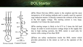
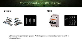
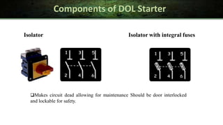
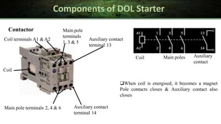
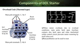
DOLSTARTER OF THREE PHASE
INDUCTIONMOTOR
By:
Engr. Mart Nikki Lou M. Mantilla, REE, RME
Starting of induction motor
A 3-phase induction motor is theoretically self starting. The stator of an
induction motor consists of 3-phase windings, which when connected to
a 3-phase supply creates a rotating magnetic field. This will link and cut
the rotor conductors which in turn will induce a current in the rotor
conductors and create a rotor magnetic field. The magnetic field created
by the rotor will interact with the rotating magnetic field in the stator
and produce rotation.
Therefore, 3-phase induction motors employ a starting method not to
provide a starting torque at the rotor, but because of the following
reasons;
1) Reduce heavy starting currents and prevent motor from overheating.
2) Provide overload and no-voltage protection.
Three Phase Induction Motor
Starting methods of Induction Motor
There are many methods in use to start 3-phase induction motors.
Some of the common methods are;
Direct On-Line Starter (DOL)
Star-Delta Starter
Auto Transformer Starter
Rotor Impedance Starter
Power Electronics Starter
DOL Starter
The Direct On-Line (DOL) starter is the simplest and the most
inexpensive of all starting methods and is usually used for squirrel
cage induction motors. It directly connects the contacts of the motor
to the full supply voltage. The starting current is very large,
normally 6 to 8 times the rated current.
The starting torque is likely to be 0.75 to 2 times the full load
torque. In order to avoid excessive voltage drops in the supply line
due to high starting currents, the DOL starter is used only for
motors with a rating of less than 5KW
There are safety mechanisms inside the DOL starter which
provides protection to the motor as well as the operator of the
motor.
Components of DOL Starter
FUSES MCB
Designed to operate very quickly Protect against short circuit currents to earth or
between phases.
Components of DOL Starter
Isolator
Makes circuit dead allowing for maintenance Should be door interlocked
and lockable for safety.
Isolator with integral fuses
Components of DOL Starter
Coil
Contactor
Coil terminals A1 &A2
Main pole terminals 2, 4 & 6
Main pole
terminals
1, 3 & 5
Auxiliary contact
terminal 13
Auxiliary contact
terminal 14
Coil Main poles Auxiliary
contact
When coil is energised, it becomes a magnet
Pole contacts closes & Auxiliary contact also
closes
Components of DOL Starter
When motor overheats due to overload
conditions, main poles latch open Auxiliary
contacts also latch open and when interlocked
within control circuit prevents motor restarting by
itself when cool.
Red pushbutton can be used to reset
Main pole terminals 2, 4 & 6
N/O
Auxiliary
contacts
97 & 98
N/C
Auxiliary
contacts
95 & 96
Overload Unit (Thermal type)
Main pole terminals 1, 3 & 5
Reset
button
Components of DOL Starter
Start and Stop pushbuttons
Start button is green and flush mounted Stop button is red and protruding
N/O contact N/C contact
Contacts at the back of
switches can be either
N/O or N/C
Working of DOL Starter
The DOL starter consists of a coil operated contactor
K1M controlled by start and stop push buttons. On
pressing the start push button S1, the contactor coil
K1M is energized from line L1.
The three mains contacts (1-2), (3-4), and (5-6) in
figure are closed. The motor is thus connected to the
supply. When the stop push button S2 is pressed, the
supply through the contactor K1M is disconnected.
Since the K1M is de-energized, the main contacts (1-
2), (3-4), and (5-6) are opened. The supply to motor
is disconnected and the motor stops.
In the fault condition or Overload causes OL1 to
open, K1M coil de-energises &K1M retaining
contact drops out.
Fuses
Isolator
Contactor
K1M
Induction
Motor
Auxiliary
contact
(retainer)
Auxiliary
Overload Unit contact
OL1 (interlock)
Safety earth
3-phase
supply
Features of DOL Starter
Features of DOLstarting
For low- and medium-power three-phase motors
Three connection lines (circuit layout: star or delta)
High starting torque
Very high mechanical load
High current peaks
Voltage dips
Simple switching devices
Conclusion
The various components of DOL Starter are being studied and their
working strategies and implementation methodologies are worked upon.
An effort is being made to study the relative complexities of the
different component. Also the relative efficiency, accuracy and
processing time for each component is tried to understand.
THANK YOU…

TOPIC 4.2- D.O.L Motor Starter.pptx

  • 1.
    DOLSTARTER OF THREEPHASE INDUCTIONMOTOR By: Engr. Mart Nikki Lou M. Mantilla, REE, RME
  • 2.
    Starting of inductionmotor A 3-phase induction motor is theoretically self starting. The stator of an induction motor consists of 3-phase windings, which when connected to a 3-phase supply creates a rotating magnetic field. This will link and cut the rotor conductors which in turn will induce a current in the rotor conductors and create a rotor magnetic field. The magnetic field created by the rotor will interact with the rotating magnetic field in the stator and produce rotation. Therefore, 3-phase induction motors employ a starting method not to provide a starting torque at the rotor, but because of the following reasons; 1) Reduce heavy starting currents and prevent motor from overheating. 2) Provide overload and no-voltage protection. Three Phase Induction Motor
  • 3.
    Starting methods ofInduction Motor There are many methods in use to start 3-phase induction motors. Some of the common methods are; Direct On-Line Starter (DOL) Star-Delta Starter Auto Transformer Starter Rotor Impedance Starter Power Electronics Starter
  • 4.
    DOL Starter The DirectOn-Line (DOL) starter is the simplest and the most inexpensive of all starting methods and is usually used for squirrel cage induction motors. It directly connects the contacts of the motor to the full supply voltage. The starting current is very large, normally 6 to 8 times the rated current. The starting torque is likely to be 0.75 to 2 times the full load torque. In order to avoid excessive voltage drops in the supply line due to high starting currents, the DOL starter is used only for motors with a rating of less than 5KW There are safety mechanisms inside the DOL starter which provides protection to the motor as well as the operator of the motor.
  • 5.
    Components of DOLStarter FUSES MCB Designed to operate very quickly Protect against short circuit currents to earth or between phases.
  • 6.
    Components of DOLStarter Isolator Makes circuit dead allowing for maintenance Should be door interlocked and lockable for safety. Isolator with integral fuses
  • 7.
    Components of DOLStarter Coil Contactor Coil terminals A1 &A2 Main pole terminals 2, 4 & 6 Main pole terminals 1, 3 & 5 Auxiliary contact terminal 13 Auxiliary contact terminal 14 Coil Main poles Auxiliary contact When coil is energised, it becomes a magnet Pole contacts closes & Auxiliary contact also closes
  • 8.
    Components of DOLStarter When motor overheats due to overload conditions, main poles latch open Auxiliary contacts also latch open and when interlocked within control circuit prevents motor restarting by itself when cool. Red pushbutton can be used to reset Main pole terminals 2, 4 & 6 N/O Auxiliary contacts 97 & 98 N/C Auxiliary contacts 95 & 96 Overload Unit (Thermal type) Main pole terminals 1, 3 & 5 Reset button
  • 9.
    Components of DOLStarter Start and Stop pushbuttons Start button is green and flush mounted Stop button is red and protruding N/O contact N/C contact Contacts at the back of switches can be either N/O or N/C
  • 10.
    Working of DOLStarter The DOL starter consists of a coil operated contactor K1M controlled by start and stop push buttons. On pressing the start push button S1, the contactor coil K1M is energized from line L1. The three mains contacts (1-2), (3-4), and (5-6) in figure are closed. The motor is thus connected to the supply. When the stop push button S2 is pressed, the supply through the contactor K1M is disconnected. Since the K1M is de-energized, the main contacts (1- 2), (3-4), and (5-6) are opened. The supply to motor is disconnected and the motor stops. In the fault condition or Overload causes OL1 to open, K1M coil de-energises &K1M retaining contact drops out. Fuses Isolator Contactor K1M Induction Motor Auxiliary contact (retainer) Auxiliary Overload Unit contact OL1 (interlock) Safety earth 3-phase supply
  • 11.
    Features of DOLStarter Features of DOLstarting For low- and medium-power three-phase motors Three connection lines (circuit layout: star or delta) High starting torque Very high mechanical load High current peaks Voltage dips Simple switching devices
  • 12.
    Conclusion The various componentsof DOL Starter are being studied and their working strategies and implementation methodologies are worked upon. An effort is being made to study the relative complexities of the different component. Also the relative efficiency, accuracy and processing time for each component is tried to understand.
  • 13.