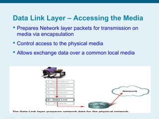
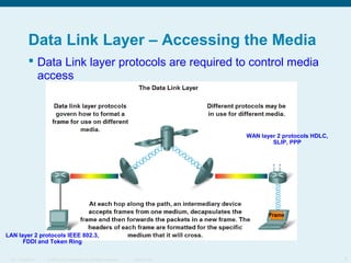
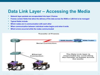
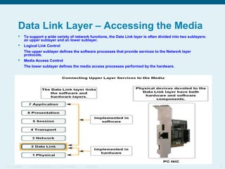
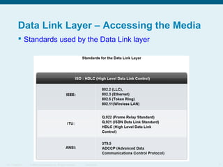
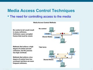
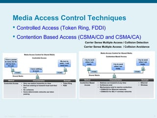
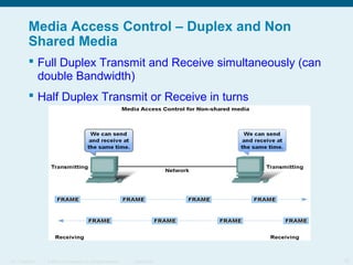
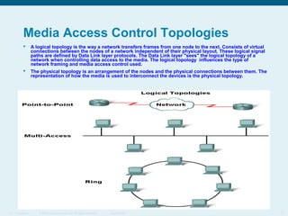
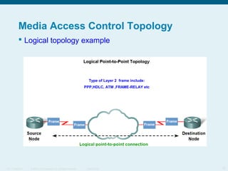
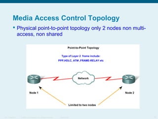
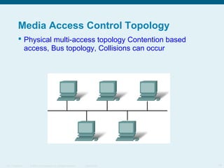
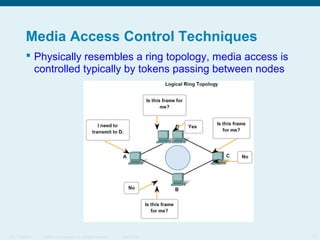
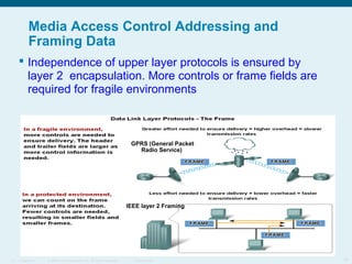
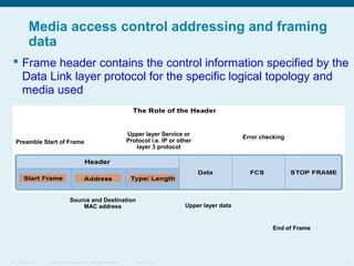
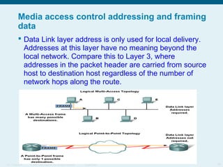
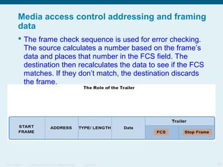
This document discusses the data link layer, which prepares network layer packets for transmission by encapsulating them into frames. It identifies common data link layer protocols for both LANs and WANs. The data link layer controls media access through logical link control and media access control sublayers. Media access control methods include controlled access like token ring and contention-based access like CSMA/CD. Frame structure is also discussed, with frames containing source/destination addresses, error checking fields, and encapsulated network layer data. Different frame types are used depending on the logical and physical network topology.
The Application layer provides the interface to the user.
The Transport layer is responsible for dividing and managing communications between the processes running in the two end systems.
The Network layer protocols organize our communication data so that it can travel across internetworks from the originating host to a destination host.
It is the role of the OSI Data Link layer to prepare Network layer packets for transmission and to control access to the physical media.
The Data Link layer provides a means for exchanging data over a common local media.
The Data Link layer performs two basic services:
Allows the upper layers to access the media using techniques such as framing
Controls how data is placed onto the media and is received from the media using techniques such as media access control and error detection
The Data Link layer is responsible for the exchange of frames between nodes over the media of a physical network.
In any given exchange of Network layer packets, there may be numerous Data Link layer and media transitions. At each hop along the path, an intermediary device - usually a router - accepts frames from a medium, decapsulates the frame, and then forwards the packet in a new frame appropriate to the medium of that segment of the physical network.
Layer 2 protocols specify the encapsulation of a packet into a frame and the techniques for getting the encapsulated packet on and off each medium. The technique used for getting the frame on and off media is called the media access control method. For the data to be transferred across a number of different media, different media access control methods may be required during the course of a single communication.
The media access control methods described by the Data Link layer protocols define the processes by which network devices can access the network media and transmit frames in diverse network environments.
Data Link layer protocols require control information to enable the protocols to function. Control information may tell:
Which nodes are in communication with each other
When communication between individual nodes begins and when it ends
Which errors occurred while the nodes communicated
Which nodes will communicate next
The Data Link layer frame includes:
Data - The packet from the Network layer
Header - Contains control information, such addressing, and is located at the beginning of the PDU
Trailer - Contains control information added to the end of the PDU
Typical field types include:
Start and stop indicator fields - The beginning and end limits of the frame
Naming or addressing fields
Type field - The type of PDU contained in the frame
Quality - control fields
A data field -The frame payload (Network layer packet)
To support a wide variety of network functions, the Data Link layer is often divided into two sublayers: an upper sublayer and an lower sublayer.
Logical Link Control
The upper sublayer defines the software processes that provide services to the Network layer protocols.
Media Access Control
The lower sublayer defines the media access processes performed by the hardware.
Regulating the placement of data frames onto the media is known as media access control. Among the different implementations of the Data Link layer protocols, there are different methods of controlling access to the media. These media access control techniques define if and how the nodes share the media.
The method of media access control used depends on:
Media sharing - If and how the nodes share the media
Topology - How the connection between the nodes appears to the Data Link layer
There are two basic media access control methods for shared media:
Controlled - Each node has its own time to use the medium
Contention-based - All nodes compete for the use of the medium
In full-duplex communication, both devices can transmit and receive on the media at the same time. The Data Link layer assumes that the media is available for transmission for both nodes at any time. Therefore, there is no media arbitration necessary in the Data Link layer.
The topology of a network is the arrangement or relationship of the network devices and the interconnections between them. Network topologies can be viewed at the physical level and the logical level.
The physical topology is an arrangement of the nodes and the physical connections between them. The representation of how the media is used to interconnect the devices is the physical topology.
A logical topology is the way a network transfers frames from one node to the next. This arrangement consists of virtual connections between the nodes of a network independent of their physical layout. These logical signal paths are defined by Data Link layer protocols. The Data Link layer "sees" the logical topology of a network when controlling data access to the media. It is the logical topology that influences the type of network framing and media access control used.
The end nodes communicating in a point-to-point network can be physically connected via a number of intermediate devices. However the use of physical devices in the network does not affect the logical topology.
In some cases, the logical connection between nodes forms what is called a virtual circuit. A virtual circuit is a logical connection created within a network between two network devices. The two nodes on either end of the virtual circuit exchange the frames with each other.
Link layer protocols that describe Data Link layer frames, each frame type has three basic parts:
Header
Data
Trailer
All Data Link layer protocols encapsulate the Layer 3 PDU within the data field of the frame. However, the structure of the frame and the fields contained in the header and trailer vary according to the protocol.
The Data Link layer protocol describes the features required for the transport of packets across different media. These features of the protocol are integrated into the encapsulation of the frame. When the frame arrives at its destination and the Data Link protocol takes the frame off the media, the framing information is read and discarded.
As shown in the figure, the frame header contains the control information specified by the Data Link layer protocol for the specific logical topology and media used.
Frame control information is unique to each type of protocol. It is used by the Layer 2 protocol to provide features demanded by the communication environment.
Typical frame header fields include:
Start Frame field - Indicates the beginning of the frame
Source and Destination address fields - Indicates the source and destination nodes on the media
Priority/Quality of Service field - Indicates a particular type of communication service for processing
Type field - Indicates the upper layer service contained in the frame
Logical connection control field - Used to establish a logical connection between nodes
Physical link control field - Used to establish the media link
Flow control field - Used to start and stop traffic over the media
Congestion control field - Indicates congestion in the media
Because the frame is only used to transport data between nodes across the local media, the Data Link layer address is only used for local delivery. Addresses at this layer have no meaning beyond the local network. Compare this to Layer 3, where addresses in the packet header are carried from source host to destination host regardless of the number of network hops along the route.
If the packet in the frame must pass onto another network segment, the intermediate device - a router - will decapsulate the original frame, create a new frame for the packet, and send it onto the new segment. The new frame will use source and destination addressing as necessary to transport the packet across the new media.
The frame check sequence is used for error checking. The source calculates a number based on the frame’s data and places that number in the FCS field. The destination then recalculates the data to see if the FCS matches. If they don’t match, the destination discards the frame.