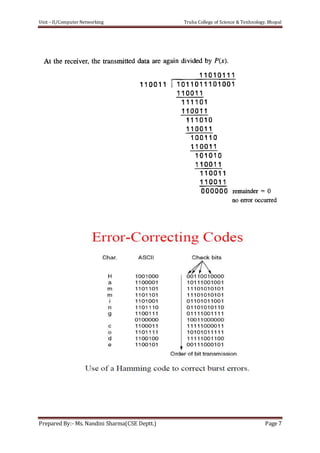
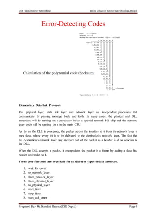
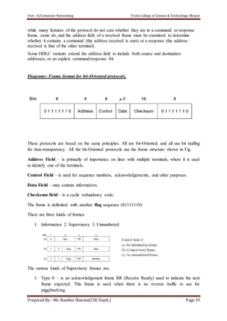
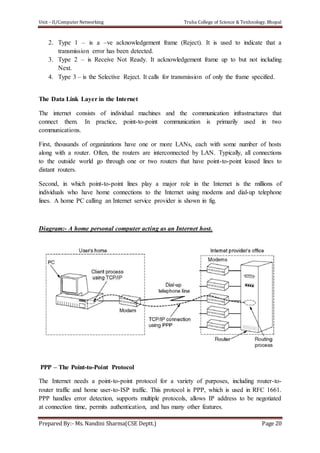
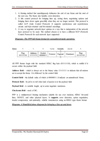
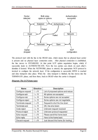
Downloaded 297 times
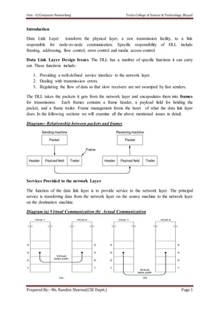
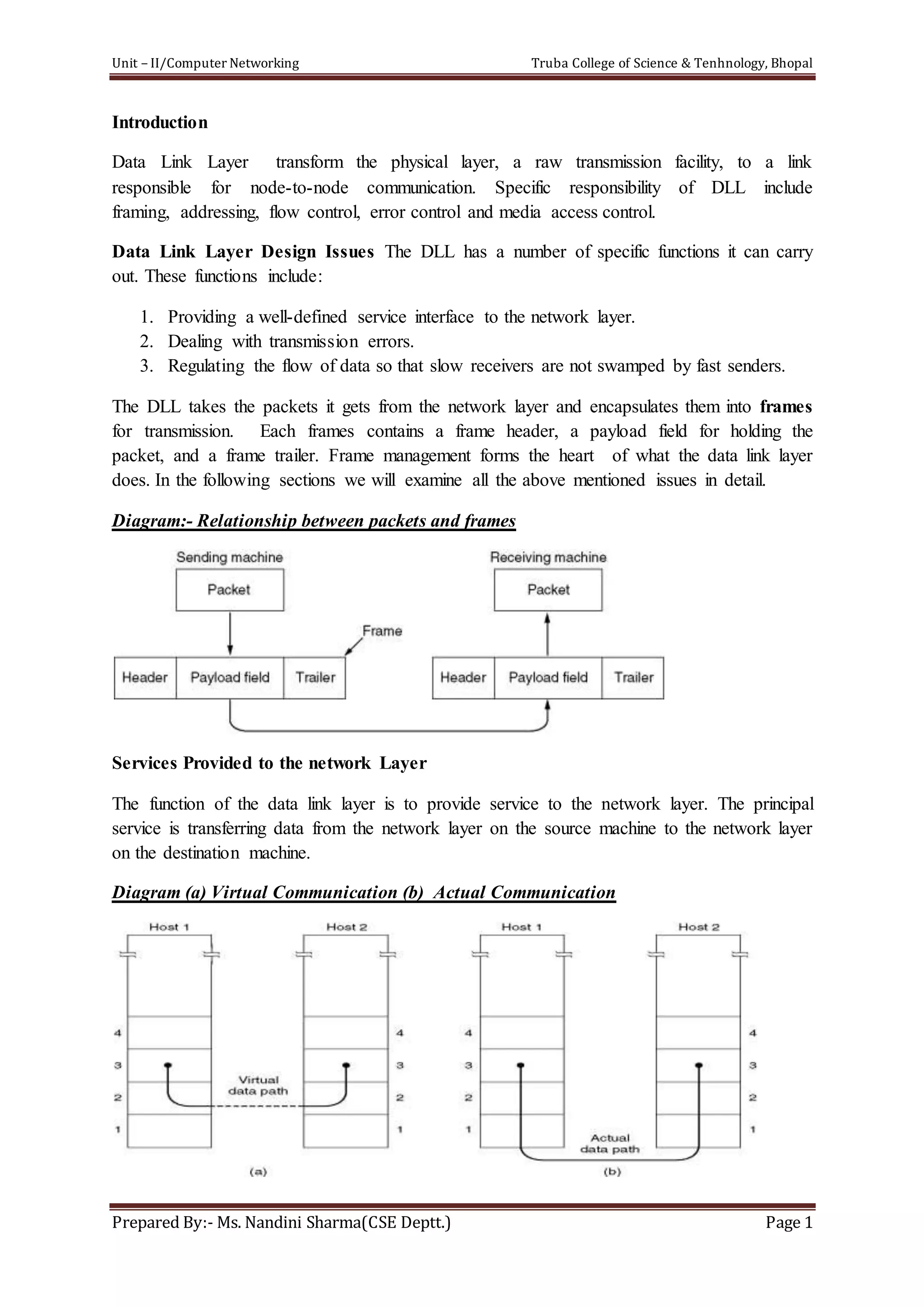
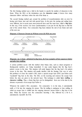
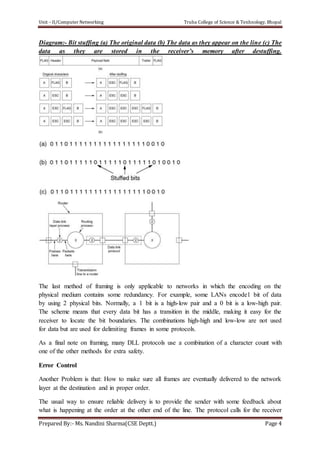
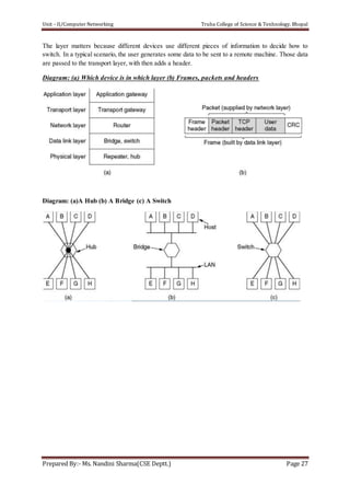

The document discusses the Data Link Layer (DLL) in computer networking, detailing its functions such as framing, addressing, flow control, error control, and media access control. It outlines various services provided by the DLL like unacknowledged connectionless service and acknowledged connection-oriented service, along with methods for framing like byte stuffing and character counting. The document also addresses error and flow control mechanisms, emphasizing the importance of transmission reliability and managing data flow between sender and receiver.