
Recommended
Recommended
More Related Content
What's hot
What's hot (20)
Viewers also liked
Viewers also liked (20)
Similar to 4
Similar to 4 (20)
4
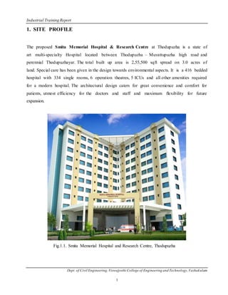
- 1. Industrial Training Report Dept. of Civil Engineering,Viswajyothi College of Engineering and Technology,Vazhakulam 1 1. SITE PROFILE The proposed Smita Memorial Hospital & Research Centre at Thodupuzha is a state of art multi-specialty Hospital located between Thodupuzha – Muvattupuzha high road and perennial Thodupuzhayar. The total built up area is 2,55,500 sqft spread on 3.0 acres of land. Special care has been given in the design towards environmental aspects. It is a 416 bedded hospital with 334 single rooms, 6 operation theatres, 5 ICUs and all other amenities required for a modern hospital. The architectural design caters for great convenience and comfort for patients, utmost efficiency for the doctors and staff and maximum flexibility for future expansion. Fig.1.1. Smita Memorial Hospital and Research Centre, Thodupuzha
- 2. Industrial Training Report Dept. of Civil Engineering,Viswajyothi College of Engineering and Technology,Vazhakulam 2 2. FAMILIARISATION OF IS CODES Some of the Indian Standard codes we have gone through during industrial training are the following, SL. NO IS CODES CODES FOR 1 IS 383 : 1970 Specification for coarse aggregate and fine aggregate from natural sources for concrete 2 IS 456 : 2000 Plain and Reinforced Concrete – code for practice 3 IS 516 : 1959 Method of test for strength of concrete 4 IS 800 : 1984 Code of practice for General construction in steel 5 IS 1199 : 1959 Methods of sampling and analysis of concrete 6 IS 1200 : 1992 Methods of measurement of building and civil engineering work 7 IS 13920 :1993 Ductile details of Reinforced concrete structures subjected to seismic forces 28 IS 1786 : 2008 High strength deformed steel bars and wires for concrete reinforcement- specification 9 IS 2720 : 1973 Determination of moisture content 10 IS 3385 Code of practice for measurement of civil engineering work
- 3. Industrial Training Report Dept. of Civil Engineering,Viswajyothi College of Engineering and Technology,Vazhakulam 3 3. MIX DESIGN Concrete is the basis engineering material used in most civil engineering structure. It’s popularity as basic building material in construction is because of, its economy of use, good durability and case with which it can be manufactured at site. The ability to mould it into any shape and size, because of its plasticity in green stage and its sub sequent hardening to achieve strength is particularly useful. Concrete like other engineering materials needs to be designed for properties like strength, durability, workability and cohesion. Concrete mix design is the science of deciding relative proportions of ingredients of concrete, to achieve the desired properties in the most economical way. With advent of high rise buildings and prestressed concrete, use of higher grades of concrete is becoming more common. Even the revised IS 456-2000 advocates use of higher grades concrete for more severe conditions of exposure, for durability considerations. With advent of new generation admixtures, it is possible to achieve higher grades of concrete with high workability levels economically. Use of mineral admixtures like fly ash, slag, melta kaolin and silica fume have revolutionized the concrete technology by increasing strength and durability of concrete by many folds.mix design of concrete becoming more relevant in the above scenario. However, it should be borne in mind that mix design adopted site should implemented with proper understanding and with necessary precautions. 3.1 What is Mix Design? Concrete is an extremely versatile building material because, it can be designed for strength ranging from M10 to M100 and workability ranging from 0 mm slump upto 150mm slump. In all these cases the basic ingredients of concrete are the same, but it is their relative proportion in that makes the difference. Basic ingredients of concrete 1. Cement: it is the basic building material in concrete. 2. Water: it hydrates cement and also makes concrete workable.
- 4. Industrial Training Report Dept. of Civil Engineering,Viswajyothi College of Engineering and Technology,Vazhakulam 4 3. Coarse aggregate: it is building component of concrete. 4. Fine aggregate: along with cement paste it forms mortar grout and fills voids in the coarse aggregate. 5. Admixtures: they enhance certain properties of concrete e.g. gain of strength, workability, setting properties, imperviousness etc. Decision variables in Mix Design a) Water cement ratio b) Cement content c) Relative proportion of fine aggregate to coarse aggregates Proportion of fine aggregate to coarse aggregate depends upon the following : a) Fineness of sand b) Size &shape of coarse aggregate c) Cement content Commonly used admixtures are as follows: a) Plasticizers and super plasticizers b) Retarders c) Accelerators d) Air entraining agents e) Water proofing admixtures Admixture used in this project site is Hyper Plastisizer Type G. Design mix used in this project: 1. M25 – used for stair, slab, beam. 2. M30 – used for column, lift.
- 5. Industrial Training Report Dept. of Civil Engineering,Viswajyothi College of Engineering and Technology,Vazhakulam 5 4. TESTS ON CONCRETE There are various tests conducted in the site for determining the workability and strength of concrete. They are slump test and concrete cube test. 4.1. Concrete slump test The concrete slump test is an empirical test that measures the workability of fresh concrete. More specifically, it measures the consistency of the concrete in that specific batch. This test is performed to check the consistency of freshly made concrete. Consistency is a term very closely related to workability. It is a term which describes the state of fresh concrete. It refers to the ease with which the concrete flows. It is used to indicate the degree of wetness. Workability of concrete is mainly affected by consistency i.e. wetter mixes will be more workable than drier mixes, but concrete of the same consistency may vary in workability. It is also used to determine consistency between individual batches. The test is popular due to the simplicity of apparatus used and simple procedure. Unfortunately, the simplicity of the test often allows a wide variability in the manner that the test is performed. The slump test is used to ensure uniformity for different batches of similar concrete under field conditions,[ and to ascertain the effects of plasticizers on their introduction. In Indiana this test is conducted as per IS specification. 4.1.1. Principle The slump test result is a slump of the behavior of a compacted inverted cone of concrete under the action of gravity. It measures the consistency or the wetness of concrete. 4.1.2. Apparatus The test is carried out using a mould known as a slump cone or Abrams cone. The cone is placed on a hard non-absorbent surface. This cone is filled with fresh concrete in three stages, each time it is
- 6. Industrial Training Report Dept. of Civil Engineering,Viswajyothi College of Engineering and Technology,Vazhakulam 6 tamped using a rod of standard dimensions. At the end of the third stage, concrete is struck off flush to the top of the mould. The mould is carefully lifted vertically upwards, so as not to disturb the concrete cone. Concrete subsides. This subsidence is termed as slump, and is measured in to the nearest 5 mm if the slump is <100 mm and measured to the nearest 10 mm if the slump is >100 mm. Fig.4.1.Concrete Slump Fig.4.2.Slump Test Sets For Concrete Testing 4.2 Concrete cube test Compressive strength of concrete: Out of many test applied to the concrete, this is the utmost important which gives an idea about all the characteristics of concrete. By this single test one judge that whether Concreting has been done properly or not. For cube test two types of specimens either cubes of 15 cm X 15 cm X 15 cm or 10cm X 10 cm x 10 cm depending upon the size of aggregate are used. For most of the works cubical moulds of size 15 cm x 15cm x 15 cm are commonly used. This concrete is poured in the mould and tempered properly so as not to have any voids. After 24 hours these moulds are removed and test specimens are put in water for curing. The top surface of this specimen should be made even and smooth. This is done by putting cement paste and spreading smoothly on whole area of specimen. These specimens are tested by compression testing machine after 7 days curing or 28 days curing. Load should be applied gradually at the rate of 140 kg/cm2 per minute till the Specimens fails. Load at the failure divided by area of specimen gives the compressive strength of concrete.
- 7. Industrial Training Report Dept. of Civil Engineering,Viswajyothi College of Engineering and Technology,Vazhakulam 7 Fig.4.3.Concrete Cube (150mmx150mmx150mm) Fig.4.4.Copression Testing Machine
- 8. Industrial Training Report Dept. of Civil Engineering,Viswajyothi College of Engineering and Technology,Vazhakulam 8 5. SITE VISIT 5.1 Placing of Concrete Concrete must be placed quickly and simply. Direct from a mixer truck is easiest and best. To do this the truck has to back-up to two or three sides of the job. All concrete must be properly compacted as it is placed. When a mixer truck cannot get close to the slab, means of transporting the concrete to its final position include pump, tipper, dumper and wheelbarrow. In this site concrete is transported using wheelbarrow and pumped using boom placer. Fig.5.1.Placing of Concrete 5.2 Compacting A mechanical vibrator should be used to compact the concrete every half metre over the length of the beam and hold it in place until the concrete settles and bubbles stop rising to the surface. Hold the vibrator straight up and be careful not to move the steel reinforcement, or damage the underlay or formwork. Fig.5.2.Compaction of Concrete
- 9. Industrial Training Report Dept. of Civil Engineering,Viswajyothi College of Engineering and Technology,Vazhakulam 9 5.3 Finishing When the concrete compaction is done, the slab should be roughly floated with a trowel to give a smooth surface. After floating, The slab should be left to set hard enough so that a man standing on his heels will not sink more than 5 mm into the concrete. Free water (bleed water) will rise to the surface of the slab after it is leveled. Wait until the surface water dries before the final float or trowel finishing. On a cold day the bleed water may have to be dragged off by pulling a rope or hose over the surface. Never spread dry cement or sand over the slab to absorb the bleed water as this will make the finished surface weak and dusty Fig.5.3.Finishing Of Concrete 5.4 Column Construction Column or pillar in architecture and structural engineering is a structural element that transmits, through compression, the weight of the structure above to other structural elements below. In other words, a column is a compression member. The term column applies especially to a large round support (the shaft of the column) with a capital and a base or pedestal and made of stone or appearing to be so. A small wooden or metal support is typically called a post, and supports with a rectangular or other non-round section are usually called piers.
- 10. Industrial Training Report Dept. of Civil Engineering,Viswajyothi College of Engineering and Technology,Vazhakulam 10 For the purpose of wind or earthquake engineering, columns may be designed to resist lateral forces. Other compression members are often termed "columns" because of the similar stress conditions. Columns are frequently used to support beams or arches on which the upper parts of walls or ceilings rest. In architecture, "column" refers to such a structural element that also has certain proportional and decorative features. A column might also be a decorative element not needed for structural purposes; many columns are "engaged", that is to say form part of a wall. Fig.5.4.Column Construction 5.5 Column Reinforcement A column is a slender, vertical member that carries a superimposed load. Concrete columns, especially those subjected to bending stresses, must always be reinforced with steel. In concrete columns, vertical reinforcement is the principal reinforcement. However, a loaded column shortens vertically and expands laterally; hence, lateral reinforcements in the form of lateral ties are used to restrain the expansion. Columns reinforced in this manner are called tied columns. If the restraining reinforcement is a continuous winding spiral that encircles the core and longitudinal steel, the column is called a spiral column.
- 11. Industrial Training Report Dept. of Civil Engineering,Viswajyothi College of Engineering and Technology,Vazhakulam 11 Fig.5.5.Column and Slab Reinforcement Coupling of reinforcements: Lapped joints are not appropriate, particularily when large diameter bars are involved. The use of couplers can simplify the design and construction of reinforced concrete, and reduce the amount of reinforcement being used. Fig.5.6.Coupling of Reinforcement
- 12. Industrial Training Report Dept. of Civil Engineering,Viswajyothi College of Engineering and Technology,Vazhakulam 12 Fig.5.7.Coupler 5.6 BEAM CONSTRUCTION A beam is a structural element that is capable of withstanding load primarily by resisting bending. The bending force induced into the material of the beam as a result of the external loads, own weight, span and external reactions to these loads is called a bending moment. Beams are characterized by their profile (shape of cross-section), their length, and their material. Beams are traditionally descriptions of building or civil engineering structural elements, but smaller structures such as truck or automobile frames, machine frames, and other mechanical or structural systems contain beam structures that are designed and analyzed in a similar fashion. Fig.5.8.Beam Construction
- 13. Industrial Training Report Dept. of Civil Engineering,Viswajyothi College of Engineering and Technology,Vazhakulam 13 6. QUALITY CONTROLMETHODS AND SAFETYIN THE CONSTRUCTION SITE 6.1 Quality Control Quality control and safety represent increasingly important concerns for project managers. Defects or failures in constructed facilities can result in very large costs. Even with minor defects, re- construction may be required and facility operations impaired. Increased costs and delays are the result. In the worst case, failures may cause personal injuries or fatalities. Accidents during the construction process can similarly result in personal injuries and large costs. Indirect costs of insurance, inspection and regulation are increasing rapidly due to these increased direct costs. Good project managers try to ensure that the job is done right the first time and that no major accidents occur on the project. As with cost control, the most important decisions regarding the quality of a completed facility are made during the design and planning stages rather than during construction. It is during these preliminary stages that component configurations, material specifications and functional performance are decided. Quality control during construction consists largely of insuring conformance to this original design and planning decisions. While conformance to existing design decisions is the primary focus of quality control, there are exceptions to this rule. First, unforeseen circumstances, incorrect design decisions or changes desired by an owner in the facility function may require re-evaluation of design decisions during the course of construction. While these changes may be motivated by the concern for quality, they represent occasions for re-design with all the attendant objectives and constraints. As a second case, some designs rely upon informed and appropriate decision making during the construction process itself. For example, some tunneling methods make decisions about the amount of shoring required at different locations based upon observation of soil conditions during the tunneling process. Since such decisions are based on better information concerning actual site conditions, the facility design may be more cost effective as a result.
- 14. Industrial Training Report Dept. of Civil Engineering,Viswajyothi College of Engineering and Technology,Vazhakulam 14 With the attention to conformance as the measure of quality during the construction process, the specification of quality requirements in the design and contract documentation becomes extremely important. Quality requirements should be clear and verifiable, so that all parties in the project can understand the requirements for conformance. Much of the discussion in this chapter relates to the development and the implications of different quality requirements for construction as well as the issues associated with insuring conformance. Safety during the construction project is also influenced in large part by decisions made during the planning and design process. Some designs or construction plans are inherently difficult and dangerous to implement, whereas other, comparable plans may considerably reduce the possibility of accidents. For example, clear separation of traffic from construction zones during roadway rehabilitation can greatly reduce the possibility of accidental collisions. Beyond these design decisions, safety largely depends upon education, vigilance and cooperation during the construction process. Workers should be constantly alert to the possibilities of accidents and avoid taken unnecessary risks. 6.2 Safety Provisions for High Rise Buildings 6.2.1. Staircase (1) Every high rise building shall have at least two staircases. (2) The height of the handrail in the staircase shall not be less than 90 cms. and if balusters are provided no gap in the balusters shall be more than 10 cms wide. 6.2.2. Guard rails or parapets Every slab or balcony overlooking any exterior or interior open space which is 2 metres or more below shall be provided with parapet walls or guard rails of height not less than 1.20 metres and such guard rails shall be firmly fixed to the walls and slabs and may also be of blank walls, metal grills or a combination of both, provided that if metal grills are used they shall not be made of
- 15. Industrial Training Report Dept. of Civil Engineering,Viswajyothi College of Engineering and Technology,Vazhakulam 15 continuous horizontal members to prevent climbing on them and provided further that guard rails shall not be made of glass or any similar material which are not reinforced to prevent breaking. 6.2.3. Fire escape stairway (1) Every high rise building shall be provided with a fire escape stairway. (2) Fire escape stairway shall be directly connected with public or common areas on all floors and shall lead directly to the ground. (3) At least one side of the stairway shall be an external wall either with large openings or with break open glass to facilitate rescue operations during an emergency. (4) External fire escape staircase shall have straight flight not less than 75 cm wide, with 20 cm treads and risers not more than 19 cm. the number of risers shall he limited to 16 per flight. (5) The height of handrails shall be not less than 100 cm and not more than 120 cm. (6) The use of spiral staircase as external fire escape stairway shall be limited to buildings with height not exceeding 10 metres. (7) A spiral fire escape stairway shall be not less than 150 cm in diameter and shall be so designed as to give adequate headroom. 6.2.4. Ducts Every opening provided to ducts from the interior of a building shall be closed with strong materials. 6.2.5. Lift for residential apartments Every high rise apartment building having more than 16 dwelling units shall be provided with at least one lift capable of carrying a stretcher.Provided that if only one lift is required for the building as per the rule 48, that lift shall be one capable of carrying a stretcher.
- 16. Industrial Training Report Dept. of Civil Engineering,Viswajyothi College of Engineering and Technology,Vazhakulam 16 6.2.6. Parapets to terrace floor Where access is provided over the terrace floor or to the terrace floor, the edges of the terrace floor shall be provided with parapet walls made of stable materials to a height of not less than 120 cms. 6.2.7. Structural design Application for construction or reconstruction or addition or alteration of any high rise building shall be accompanied by one set of structural design, including that regarding seismic forces as per the provisions contained in the National Building Code of India as amended from time to time and drawings and a structural stability certificate prepared and issued by a registered engineering Fig.6.1.Safety Provisions for Workers
- 17. Industrial Training Report Dept. of Civil Engineering,Viswajyothi College of Engineering and Technology,Vazhakulam 17 7. CONCLUSION It was a wonderful experience at construction site of smita memorial hospital, Thodupuzha for 10 days. We gained a lot of insight regarding almost every aspect of site. We were given exposure in almost all the department at the site. The friendly welcome from all the employees is appreciating, sharing their experience and giving their peace of wisdom which they have gained in long journey of work. We hope this experience will be surely helping us in our future and also shaping our career.