Downloaded 154 times


![Elongation:
These are the particles having length considerably larger than the other two dimensions and it
is the particle whose greater dimension is 1.8 times its mean size.
Limit of elongated particles in the mixes is 45%. Thus, if the elongated particles are greater
than 45%, then the aggregate is considered undesirable for the intended use.
Elongation Index:
It is the percentage by weight of elongated particles in a sample. The Elongated index is
calculated by expressing the weight of Elongated particles as percentage of total weight of the
sample.
4.1.5 WATER ABSORPTION TEST:
Standard: IS: 2386 (Part 3) – 1963 – Method of test for aggregates for concrete (Part I) Particle
size and shape.
Equipment’s used:
Wire basket
Oven (300
0
c)
Container for filling water and suspending the basket
An air tight container
Balance[0-10 kg]
Shallow tray & absorbent clothes.
Procedure:
bout 2kg of the aggregate sample is washed thoroughly to remove fines, drained and then
placed in the wire basket and immersed in distilled water at a temperature between 22 to
32
0
C with a cover of at least 50 mm of water above the top of the basket
Immediately after the immersion the entrapped air is removed from the sample by lifting
the basket containing it 25 mm above the base of the tank and allowing it to drop 25 times
at the rate of about one drop per second. The basket and the aggregate should remain
completely immersed in water for a period of 24±0.5 hours afterwards.
Page 30 of 56 ACERC/CE/2017-2018/P.T.I.V](https://image.slidesharecdn.com/prajapatikunalomkarreport-171105193823/85/RESIDENTIAL-CONSTRUCTION-BUILDING-31-320.jpg)


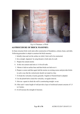


This document provides details about a residential building project constructed by Raunak Group in Mumbai. It includes a 13 storey building with 93 flats of 3 BHK configuration. The building uses shallow foundations consisting of individual, strip and raft foundations due to the soil conditions. The superstructure is constructed with reinforced concrete using materials like cement, fine and coarse aggregates, and water. Construction techniques like brick masonry and plastering are also discussed.


![internship_presentation_2022-23[1] [Autosaved].pptx](https://cdn.slidesharecdn.com/ss_thumbnails/internshippresentation2022-231autosaved-230404152500-8f1b16b7-thumbnail.jpg?width=640&height=640&fit=bounds)


