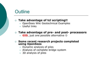
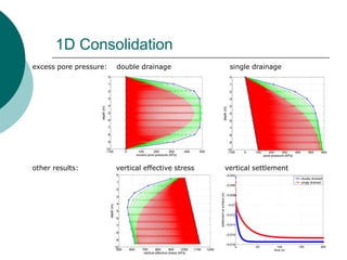
Geotechnical Examples using OpenSees 
Pedro Arduino 
University of Washington, Seattle 
OpenSees Days Portugal 2014, Workshop on Multi-Hazard Analysis of Structures using OpenSees University of Porto, Porto, Portugal Thursday July 3, 2014
Outline 
Take advantage of tcl scripting!! 
OpenSees Wiki Geotechnical Examples 
Useful links 
Take advantage of pre- and post- processors 
GID, just one possible alternative  
Some recent research projects completed using OpenSees 
Dynamic analysis of piles 
Analysis of complete bridge system 
3D analysis of piles
Take advantage of tcl scripting!! 
tcl can be used to develop scripts for geotechnical applications. 
Possible applications: 
Laterally Loaded Pile Foundation – (similar to lpile) 
One-Dimensional Consolidation 
Total Stress Site Response Analysis of a Layered Soil Column- (similar to shake) 
Effective Stress Site Response Analysis of a layered Soil Column 
Dynamic Effective Stress Analysis of a Slope 
Excavation Supported by Cantelever Sheet Pile Wall 
Other ….
OpenSees Wiki Geotechnical Examples 
http://opensees.berkeley.edu/wiki/index.php/Examples
Pseudo-Static Pile Pushover Analysis 
The pile is modeled using the dispBeamColumn element with an elastic fiber section for linear elastic constitutive behavior. 
This example describes how to run a pushover analysis of a pile in OpenSees. 
The pile and spring nodes are tied together using the equalDOF command. 
The soil is represented by p-y, t-z, and Q-z springs using the PySimple1, TzSimple1, and QzSimple1 uniaxial materials with zeroLength elements. 
The model is created in 3D. Pile nodes have 6 DOF, and the soil nodes have 3 DOF.
Pseudo-Static Pile Pushover Analysis 
results of pushover analysis for a fixed-head pile
1D Consolidation 
A column of soil is modeled in 2D using the 9_4_QuadUP element. This element has nine nodes. The nodes in the corners of the element have an additional degree-of-freedom for pore pressure. 
This example describes how to run a total 1D soil consolidation analysis in OpenSees. 
The surcharge load is applied as a constant timeseries inside of a plain load pattern. A transient analysis is conducted due to the time- dependent nature of consolidation.
1D Consolidation 
excess pore pressure: double drainage single drainage 
other results: vertical effective stress vertical settlement
Total Stress Site Response Analysis 
A layered soil profile is modeled in 2D using nodes with 2 DOF. 
This example describes how to run a total stress site response analysis in OpenSees. 
The plane strain formulation of the 4-node quadrilateral element quad is used for the soil. 
Soil constitutive models include: PressureDependMultiYield PressureIndependMultiYield 
Periodic boundary conditions are enforced in horiz. direction using the equalDOF command 
A compliant base is considered using a viscous dashpot modeled using a zeroLength element and the viscous uniaxial material.
Total Stress Site Response Analysis 
Input motion 
surface response spectra 
comparison with other analytical methods 
surface acceleration 
surface response spectra
Effective Stress Site Response Analysis 
The approach is similar to the total stress analysis. A layered soil profile is modeled in 2D with periodic displacement boundary conditions enforced using the equalDOF command and a compliant base is considered using a viscous dashpot modeled using a zeroLength element and the viscous uniaxial material. 
This example describes how to run an effective stress site response analysis in OpenSees. 
The 9_4_QuadUP element is used to model the soil. This element considers the interaction between the pore fluid and the solid soil skeleton, allowing for phenomena such as liquefaction to be modeled. 
The PressureDependMultiYield02 constitutive model is used for the soil.
Effective Stress Site Response Analysis 
summary of soil behavior at three depths within the soil profile
3D Effective Stress Site Response Analysis 
displacement of soil column during analysis with contours of excess pore pressure ratio
Dynamic Analysis of 2D Slope 
Model problem: 
This example presents a 2D effective stress analysis of a slope subject to an earthquake ground motion. 
The elements and constitutive models match those used in the site response analysis examples. 
The free-field soil response is applied to the model using free-field columns which are much more massive than the adjacent soil. 
Finite element mesh:
Dynamic Analysis of 2D Slope 
excess pore pressure ratio 
shear stress-strain 
lateral displacement 
excess pore pressure ratio contours near slope
Excavation Analysis 
This example presents a simulated excavation supported by a sheet pile wall using OpenSees. 
The InitialStateAnalysis feature is used to create the gravitational state of stress in the model without accompanying displacements. 
The plane strain formulation of the quad element is used for the soil with the PressureDependMultiYield nDMaterial for constitutive behavior. 
The sheet pile wall is modeled using the dispBeamColumn element with an elastic fiber section for linear elastic constitutive behavior. 
Soil elements to the right of the wall are progressively removed to simulate an excavation. 
The soil-wall interface is modeled using the BeamContact2D element.
Excavation Analysis 
Nodal displacement magnitude during the excavation analysis
Excavation Analysis 
shear and moment in the wall during the excavation analysis
Difficult to create tcl scripts for complex boundary value geotechnical problems. 
complex foundation configurations 
embankments 
wharves 
bridges 
3-D analysis 
Need to use pre- and post processors to create meshes and visualize results 
GID, just one possible alternative  
Take advantage of pre- and post- processors
GiD Problem Type for 2D Analysis 
Create geometry and select problemType 
Assign boundary conditions
GiD Problem Type 
Assign materials to the geometry 
Generate mesh and OpenSees input file
Some research projects completed using OpenSees 
Dynamic analysis of piles 
Analysis of complete bridge system 
3D analysis of piles
Dynamic Analysis of Piles in OpenSees
SPSI modeling in OpenSees
Two-column Bent 
Northridge motion, amax = 0.25g 
Northridge motion, amax = 0.74g
Two-span bridge
Two-span bridge 
Bent-S 
Bent-L 
Bent-M
SPSI of a complete bridge system 
• Five-span bridge 
• pile group foundation 
• abutment 
• liquefiable soil / various layers 
• lateral spreading 
• earthquake intensities 
• uncertainties
• Five-span bridge 
• Approach embankments 
• Variable thickness of liquefiable soil 
SPSI of a complete bridge system
Bearing pad spring 
Pile cap passive earth pressure spring 
abutment reaction spring 
Pressure Independent Multi Yield material 
clay 
Pressure Dependent Multi Yield material 
liquefiable soil 
py (liquefiable) 
py spring (dry sand) 
py (stiff clay) 
Nonlinear fiber beam column 
Mackie & Stojadinovic (2003) 
C 
L 
SPSI of a complete bridge system
OpenSees model 
Bridge Idealization 
SPSI of a complete bridge system
Northridge motion (0.25g) 
time 
time 
Soil Strain Profile during shaking 
SPSI of a complete bridge system
Loma Prieta (1.19g) 
time 
time 
SPSI of a complete bridge system 
Soil Strain Profile during shaking
Erzincan, Turkey 1992 (amax = 0.70g) 
displacement 
ru 
90 cm 
20 cm 
SPSI of a complete bridge system 
Max. pile demand
3D Pile Analysis 
Solid-Solid Model Beam-Solid Model
3D Pile Analysis 
Axially Loaded Piles 
 Evaluation of pile forces and accumulation of side resistance 
Self-weight forces 
Zero friction under self-weight 
Applied force at pile head 
Force at pile toe 
Full friction mobilization 
Sticking interface behavior 
Qtotal 
Qtoe 
Qtotal = Qtoe + Qside 
Qside= pB S fc dz 
fc 
fc = sh(z) tan d
3D Pile Analysis Laterally Loaded Piles (solid-beam contact element) 
Perform numerical load test 
Compare results 
3x Magnification
The beam-solid contact elements enable the use of standard beam-column elements for the pile 
This allows for simple recovery of the shear force and bending moment demands placed upon the pile 
Additionally, the surface traction acting on the pile-soil interface can be recovered and resolved into the forces applied by the soil to the pile 
3D Pile Analysis Lateral Spreading Effects
Pile Sections 
Soil Profile 
Conventional 1D Model 
3D Finite Element Model 
Comparison Between 1D & 3D 
Application Numerical Modeling of Single Pile with high-strength reinforcement and casing
Application 
Analysis of piles socketed in Rock 
3D bricks for pile and rock w/contact 
Beam for pile, 3D bricks for rock w/contact 
푉 = 휏푧푥푑퐴
Application Numerical Analysis of Mataquito River bridge 
1D Modeling Approach 
3D Modeling Approach 
Prototype 
2D Modeling Approach
Bridge deck spring 
Application Numerical Analysis of Mataquito River bridge Modeling the abutment and grouped shaft foundation
3D Applied Kinematic Model 
Application Numerical Analysis of Mataquito River bridge 3D Applied Kinematic Model
Application Numerical Analysis of Mataquito River bridge Deformation of shafts with contact forces acting on their surfaces
Liquefiable Layer 
Gravel 
Medium Dense Sand 
Dense Sand 
Fill 
Embedded Pile Cap 
Application Numerical Analysis of Llacolen bridge
Kinematic 
Deformation 
x 
z 
x 
y 
Displacement in x-direction 
Application Numerical Analysis of Llacolen bridge
Thank You! Questions? 
Universidad Nacional de Cordoba

Geotechnical Examples using OpenSees

  • 1.
    Geotechnical Examples usingOpenSees Pedro Arduino University of Washington, Seattle OpenSees Days Portugal 2014, Workshop on Multi-Hazard Analysis of Structures using OpenSees University of Porto, Porto, Portugal Thursday July 3, 2014
  • 2.
    Outline Take advantageof tcl scripting!! OpenSees Wiki Geotechnical Examples Useful links Take advantage of pre- and post- processors GID, just one possible alternative  Some recent research projects completed using OpenSees Dynamic analysis of piles Analysis of complete bridge system 3D analysis of piles
  • 3.
    Take advantage oftcl scripting!! tcl can be used to develop scripts for geotechnical applications. Possible applications: Laterally Loaded Pile Foundation – (similar to lpile) One-Dimensional Consolidation Total Stress Site Response Analysis of a Layered Soil Column- (similar to shake) Effective Stress Site Response Analysis of a layered Soil Column Dynamic Effective Stress Analysis of a Slope Excavation Supported by Cantelever Sheet Pile Wall Other ….
  • 4.
    OpenSees Wiki GeotechnicalExamples http://opensees.berkeley.edu/wiki/index.php/Examples
  • 5.
    Pseudo-Static Pile PushoverAnalysis The pile is modeled using the dispBeamColumn element with an elastic fiber section for linear elastic constitutive behavior. This example describes how to run a pushover analysis of a pile in OpenSees. The pile and spring nodes are tied together using the equalDOF command. The soil is represented by p-y, t-z, and Q-z springs using the PySimple1, TzSimple1, and QzSimple1 uniaxial materials with zeroLength elements. The model is created in 3D. Pile nodes have 6 DOF, and the soil nodes have 3 DOF.
  • 6.
    Pseudo-Static Pile PushoverAnalysis results of pushover analysis for a fixed-head pile
  • 7.
    1D Consolidation Acolumn of soil is modeled in 2D using the 9_4_QuadUP element. This element has nine nodes. The nodes in the corners of the element have an additional degree-of-freedom for pore pressure. This example describes how to run a total 1D soil consolidation analysis in OpenSees. The surcharge load is applied as a constant timeseries inside of a plain load pattern. A transient analysis is conducted due to the time- dependent nature of consolidation.
  • 8.
    1D Consolidation excesspore pressure: double drainage single drainage other results: vertical effective stress vertical settlement
  • 9.
    Total Stress SiteResponse Analysis A layered soil profile is modeled in 2D using nodes with 2 DOF. This example describes how to run a total stress site response analysis in OpenSees. The plane strain formulation of the 4-node quadrilateral element quad is used for the soil. Soil constitutive models include: PressureDependMultiYield PressureIndependMultiYield Periodic boundary conditions are enforced in horiz. direction using the equalDOF command A compliant base is considered using a viscous dashpot modeled using a zeroLength element and the viscous uniaxial material.
  • 10.
    Total Stress SiteResponse Analysis Input motion surface response spectra comparison with other analytical methods surface acceleration surface response spectra
  • 11.
    Effective Stress SiteResponse Analysis The approach is similar to the total stress analysis. A layered soil profile is modeled in 2D with periodic displacement boundary conditions enforced using the equalDOF command and a compliant base is considered using a viscous dashpot modeled using a zeroLength element and the viscous uniaxial material. This example describes how to run an effective stress site response analysis in OpenSees. The 9_4_QuadUP element is used to model the soil. This element considers the interaction between the pore fluid and the solid soil skeleton, allowing for phenomena such as liquefaction to be modeled. The PressureDependMultiYield02 constitutive model is used for the soil.
  • 12.
    Effective Stress SiteResponse Analysis summary of soil behavior at three depths within the soil profile
  • 13.
    3D Effective StressSite Response Analysis displacement of soil column during analysis with contours of excess pore pressure ratio
  • 14.
    Dynamic Analysis of2D Slope Model problem: This example presents a 2D effective stress analysis of a slope subject to an earthquake ground motion. The elements and constitutive models match those used in the site response analysis examples. The free-field soil response is applied to the model using free-field columns which are much more massive than the adjacent soil. Finite element mesh:
  • 15.
    Dynamic Analysis of2D Slope excess pore pressure ratio shear stress-strain lateral displacement excess pore pressure ratio contours near slope
  • 16.
    Excavation Analysis Thisexample presents a simulated excavation supported by a sheet pile wall using OpenSees. The InitialStateAnalysis feature is used to create the gravitational state of stress in the model without accompanying displacements. The plane strain formulation of the quad element is used for the soil with the PressureDependMultiYield nDMaterial for constitutive behavior. The sheet pile wall is modeled using the dispBeamColumn element with an elastic fiber section for linear elastic constitutive behavior. Soil elements to the right of the wall are progressively removed to simulate an excavation. The soil-wall interface is modeled using the BeamContact2D element.
  • 17.
    Excavation Analysis Nodaldisplacement magnitude during the excavation analysis
  • 18.
    Excavation Analysis shearand moment in the wall during the excavation analysis
  • 19.
    Difficult to createtcl scripts for complex boundary value geotechnical problems. complex foundation configurations embankments wharves bridges 3-D analysis Need to use pre- and post processors to create meshes and visualize results GID, just one possible alternative  Take advantage of pre- and post- processors
  • 20.
    GiD Problem Typefor 2D Analysis Create geometry and select problemType Assign boundary conditions
  • 21.
    GiD Problem Type Assign materials to the geometry Generate mesh and OpenSees input file
  • 22.
    Some research projectscompleted using OpenSees Dynamic analysis of piles Analysis of complete bridge system 3D analysis of piles
  • 23.
    Dynamic Analysis ofPiles in OpenSees
  • 24.
  • 25.
    Two-column Bent Northridgemotion, amax = 0.25g Northridge motion, amax = 0.74g
  • 26.
  • 27.
    Two-span bridge Bent-S Bent-L Bent-M
  • 28.
    SPSI of acomplete bridge system • Five-span bridge • pile group foundation • abutment • liquefiable soil / various layers • lateral spreading • earthquake intensities • uncertainties
  • 29.
    • Five-span bridge • Approach embankments • Variable thickness of liquefiable soil SPSI of a complete bridge system
  • 30.
    Bearing pad spring Pile cap passive earth pressure spring abutment reaction spring Pressure Independent Multi Yield material clay Pressure Dependent Multi Yield material liquefiable soil py (liquefiable) py spring (dry sand) py (stiff clay) Nonlinear fiber beam column Mackie & Stojadinovic (2003) C L SPSI of a complete bridge system
  • 31.
    OpenSees model BridgeIdealization SPSI of a complete bridge system
  • 32.
    Northridge motion (0.25g) time time Soil Strain Profile during shaking SPSI of a complete bridge system
  • 33.
    Loma Prieta (1.19g) time time SPSI of a complete bridge system Soil Strain Profile during shaking
  • 34.
    Erzincan, Turkey 1992(amax = 0.70g) displacement ru 90 cm 20 cm SPSI of a complete bridge system Max. pile demand
  • 35.
    3D Pile Analysis Solid-Solid Model Beam-Solid Model
  • 36.
    3D Pile Analysis Axially Loaded Piles  Evaluation of pile forces and accumulation of side resistance Self-weight forces Zero friction under self-weight Applied force at pile head Force at pile toe Full friction mobilization Sticking interface behavior Qtotal Qtoe Qtotal = Qtoe + Qside Qside= pB S fc dz fc fc = sh(z) tan d
  • 37.
    3D Pile AnalysisLaterally Loaded Piles (solid-beam contact element) Perform numerical load test Compare results 3x Magnification
  • 38.
    The beam-solid contactelements enable the use of standard beam-column elements for the pile This allows for simple recovery of the shear force and bending moment demands placed upon the pile Additionally, the surface traction acting on the pile-soil interface can be recovered and resolved into the forces applied by the soil to the pile 3D Pile Analysis Lateral Spreading Effects
  • 39.
    Pile Sections SoilProfile Conventional 1D Model 3D Finite Element Model Comparison Between 1D & 3D Application Numerical Modeling of Single Pile with high-strength reinforcement and casing
  • 40.
    Application Analysis ofpiles socketed in Rock 3D bricks for pile and rock w/contact Beam for pile, 3D bricks for rock w/contact 푉 = 휏푧푥푑퐴
  • 41.
    Application Numerical Analysisof Mataquito River bridge 1D Modeling Approach 3D Modeling Approach Prototype 2D Modeling Approach
  • 42.
    Bridge deck spring Application Numerical Analysis of Mataquito River bridge Modeling the abutment and grouped shaft foundation
  • 43.
    3D Applied KinematicModel Application Numerical Analysis of Mataquito River bridge 3D Applied Kinematic Model
  • 44.
    Application Numerical Analysisof Mataquito River bridge 3D Applied Kinematic Model
  • 45.
    Application Numerical Analysisof Mataquito River bridge 3D Applied Kinematic Model
  • 46.
    Application Numerical Analysisof Mataquito River bridge 3D Applied Kinematic Model
  • 47.
    Application Numerical Analysisof Mataquito River bridge 3D Applied Kinematic Model
  • 48.
    Application Numerical Analysisof Mataquito River bridge Deformation of shafts with contact forces acting on their surfaces
  • 49.
    Liquefiable Layer Gravel Medium Dense Sand Dense Sand Fill Embedded Pile Cap Application Numerical Analysis of Llacolen bridge
  • 50.
    Kinematic Deformation x z x y Displacement in x-direction Application Numerical Analysis of Llacolen bridge
  • 51.
    Thank You! Questions? Universidad Nacional de Cordoba