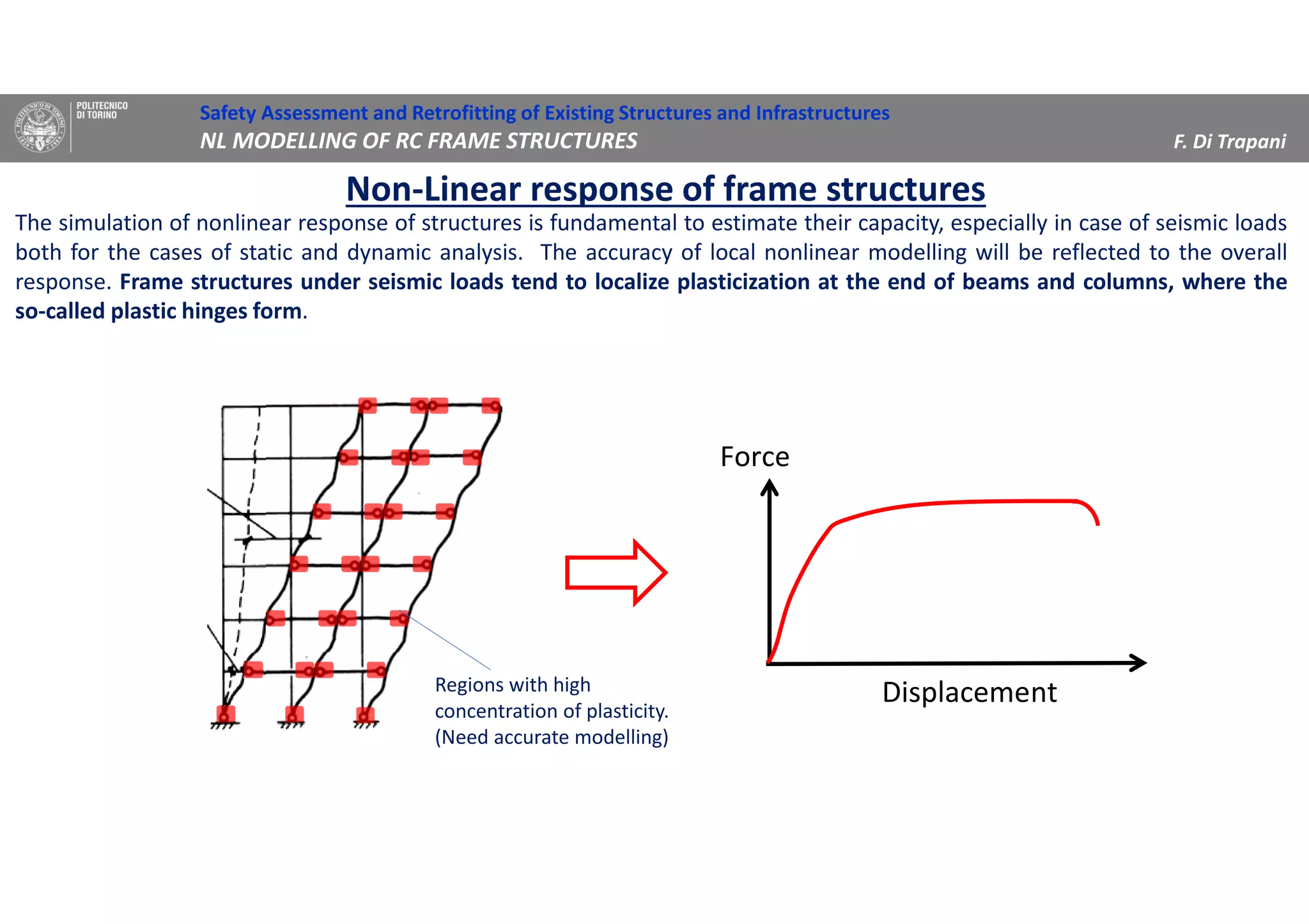
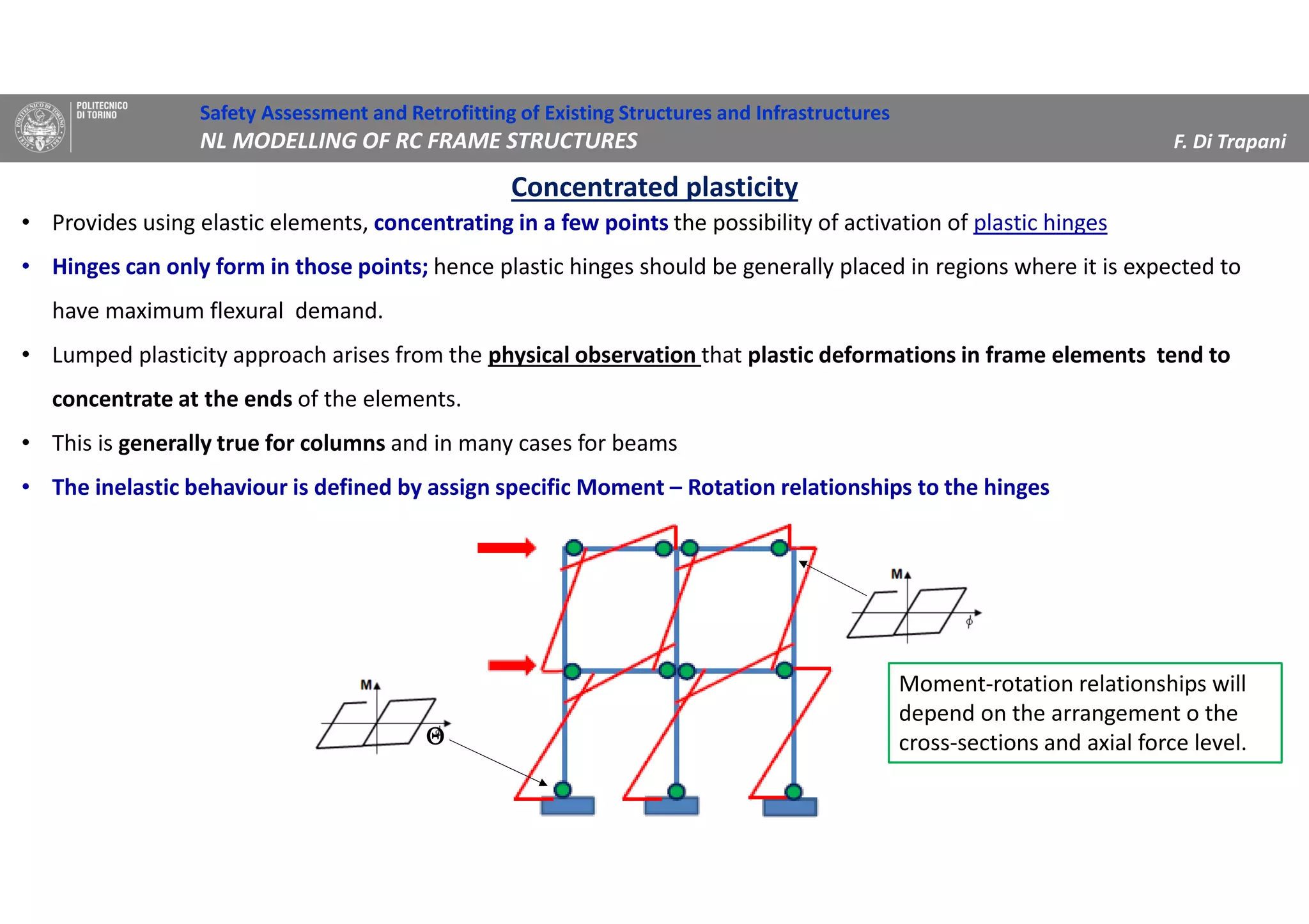
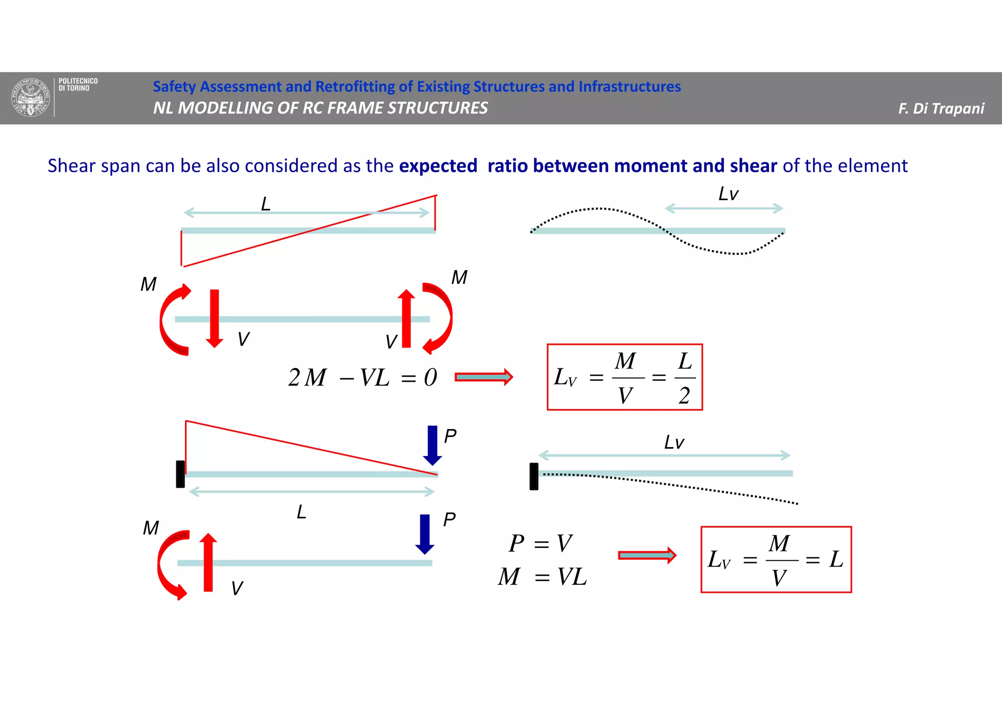
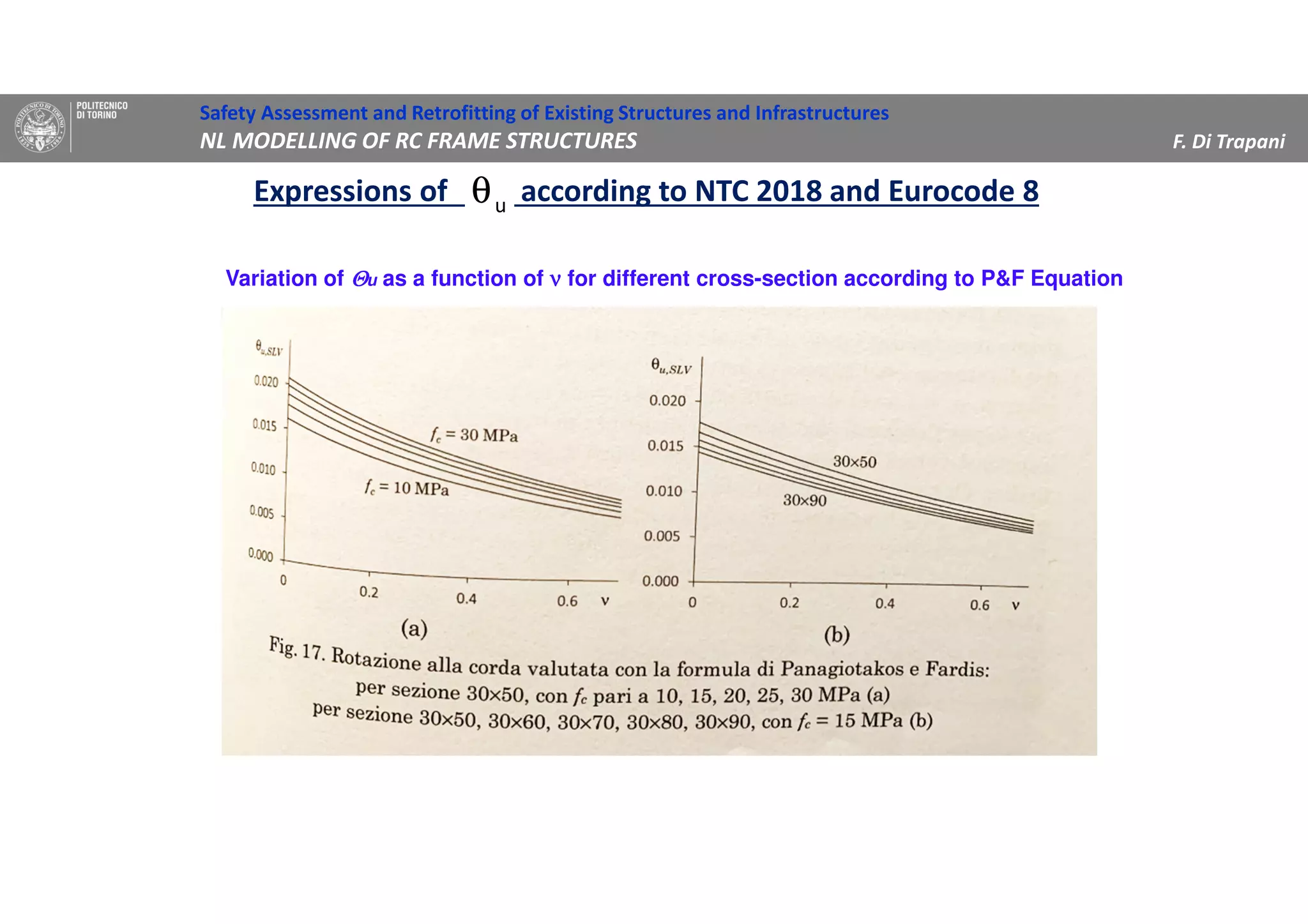
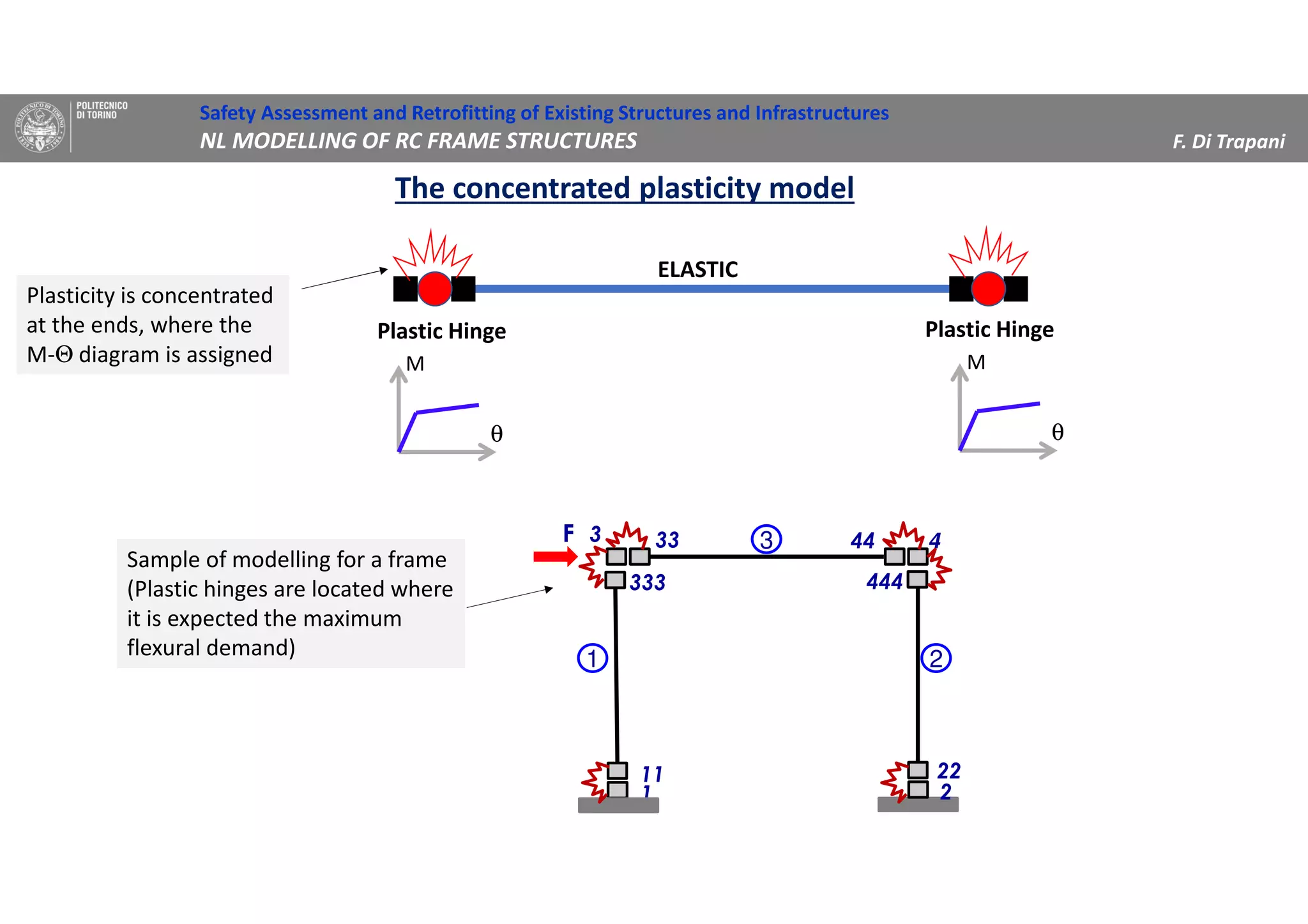
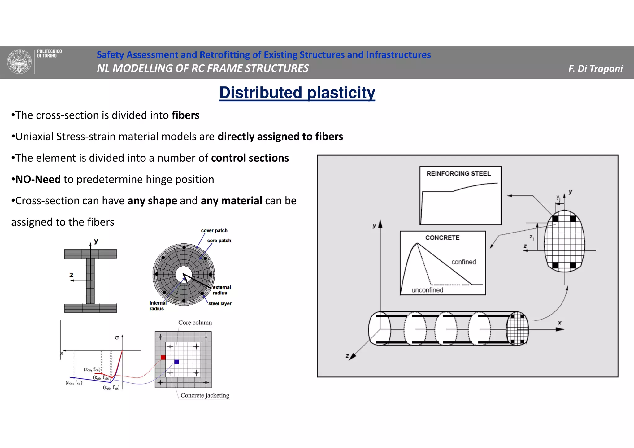
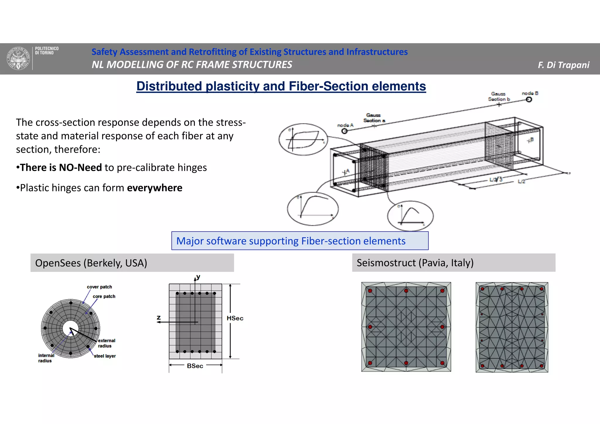
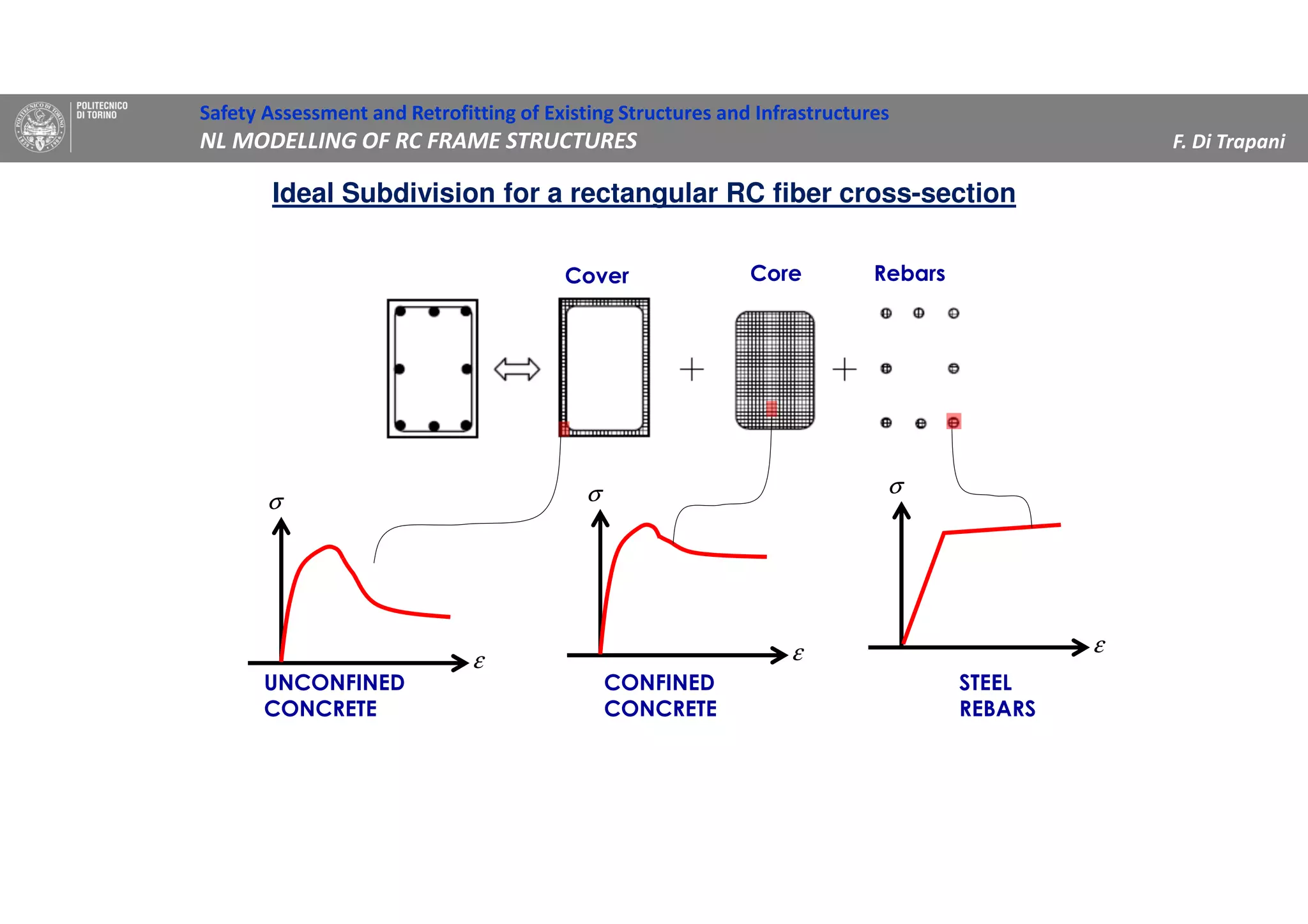
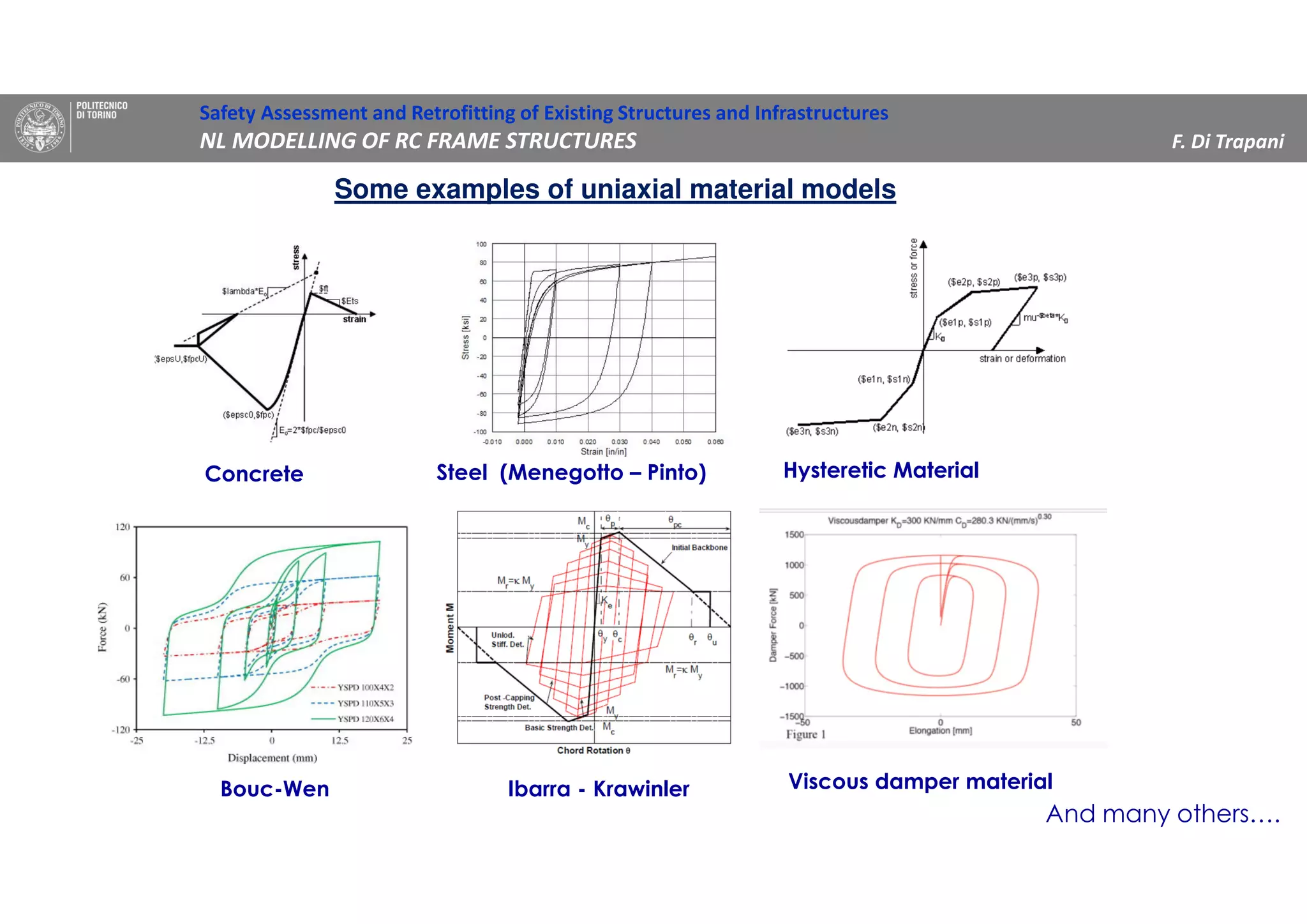
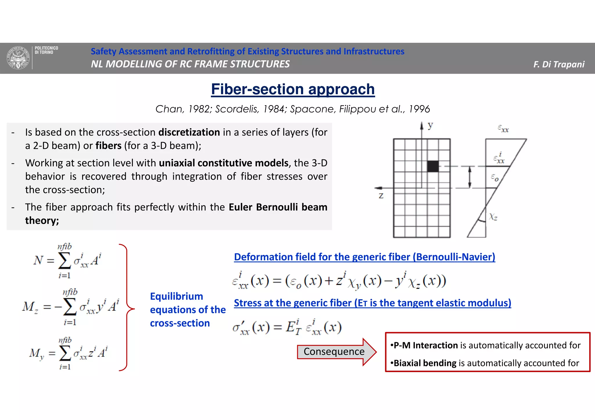
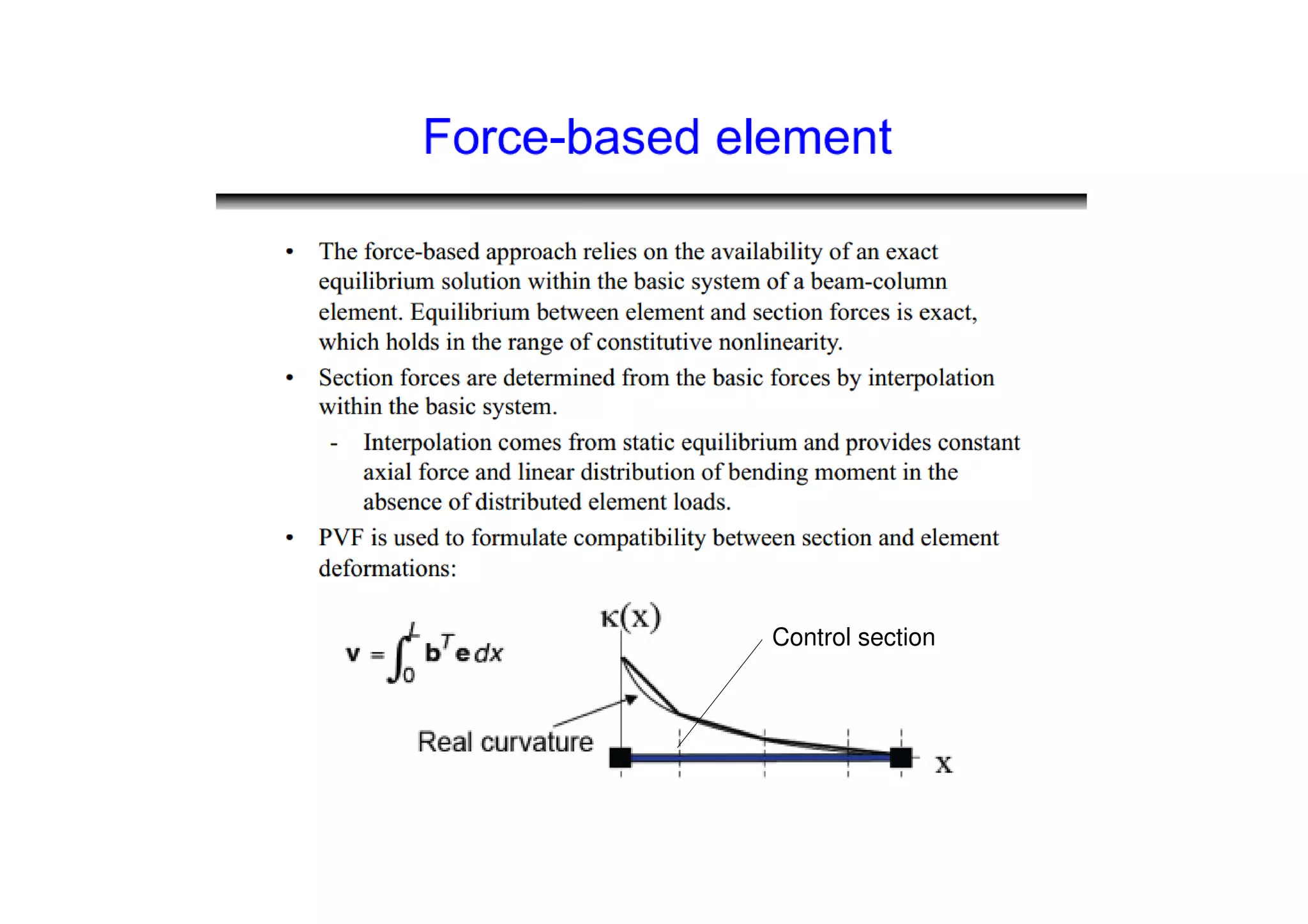
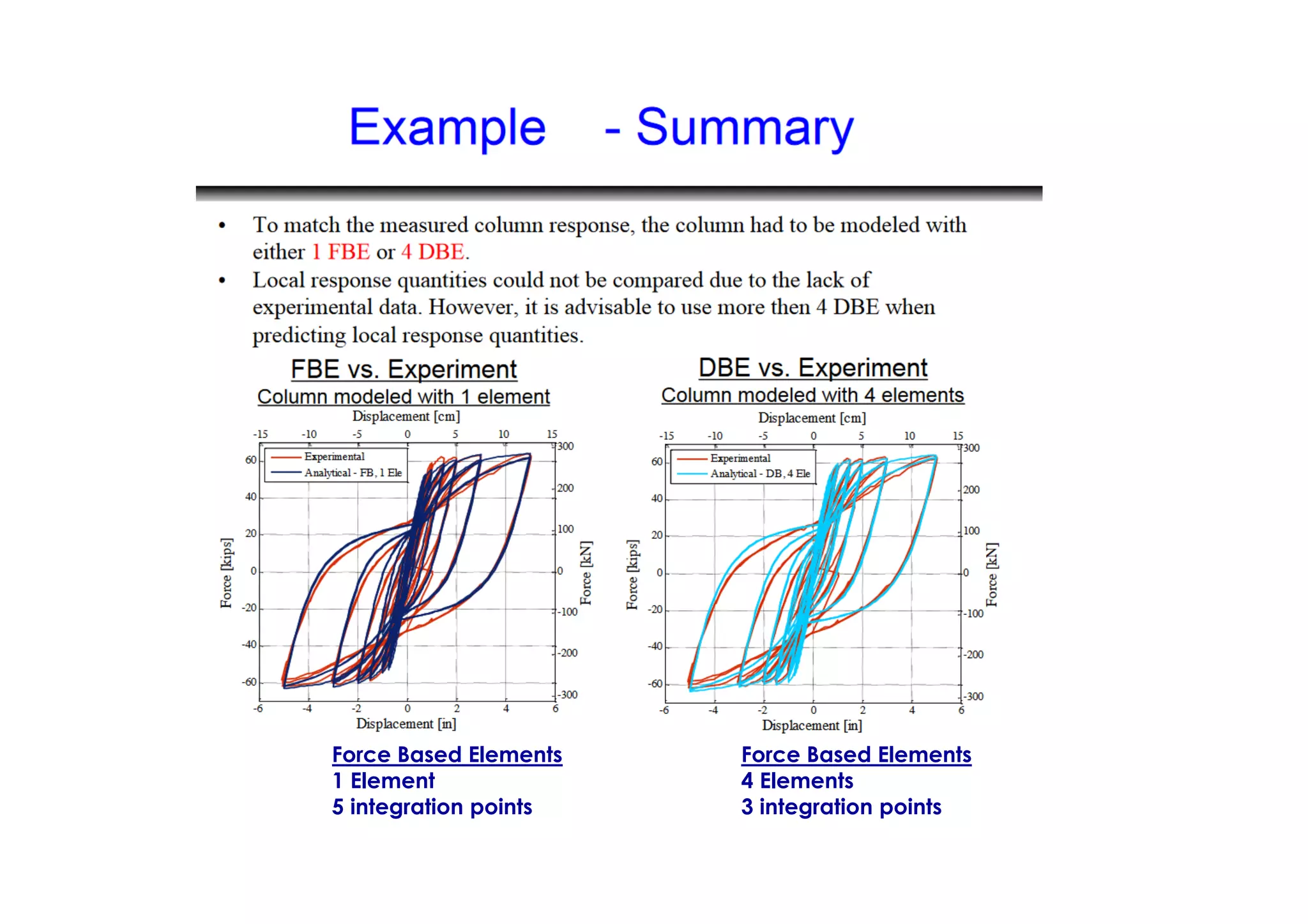
(1) The document discusses nonlinear modeling of reinforced concrete frame structures. It focuses on concentrated plasticity approaches where plasticity is concentrated at specific points, typically at the ends of beams and columns.
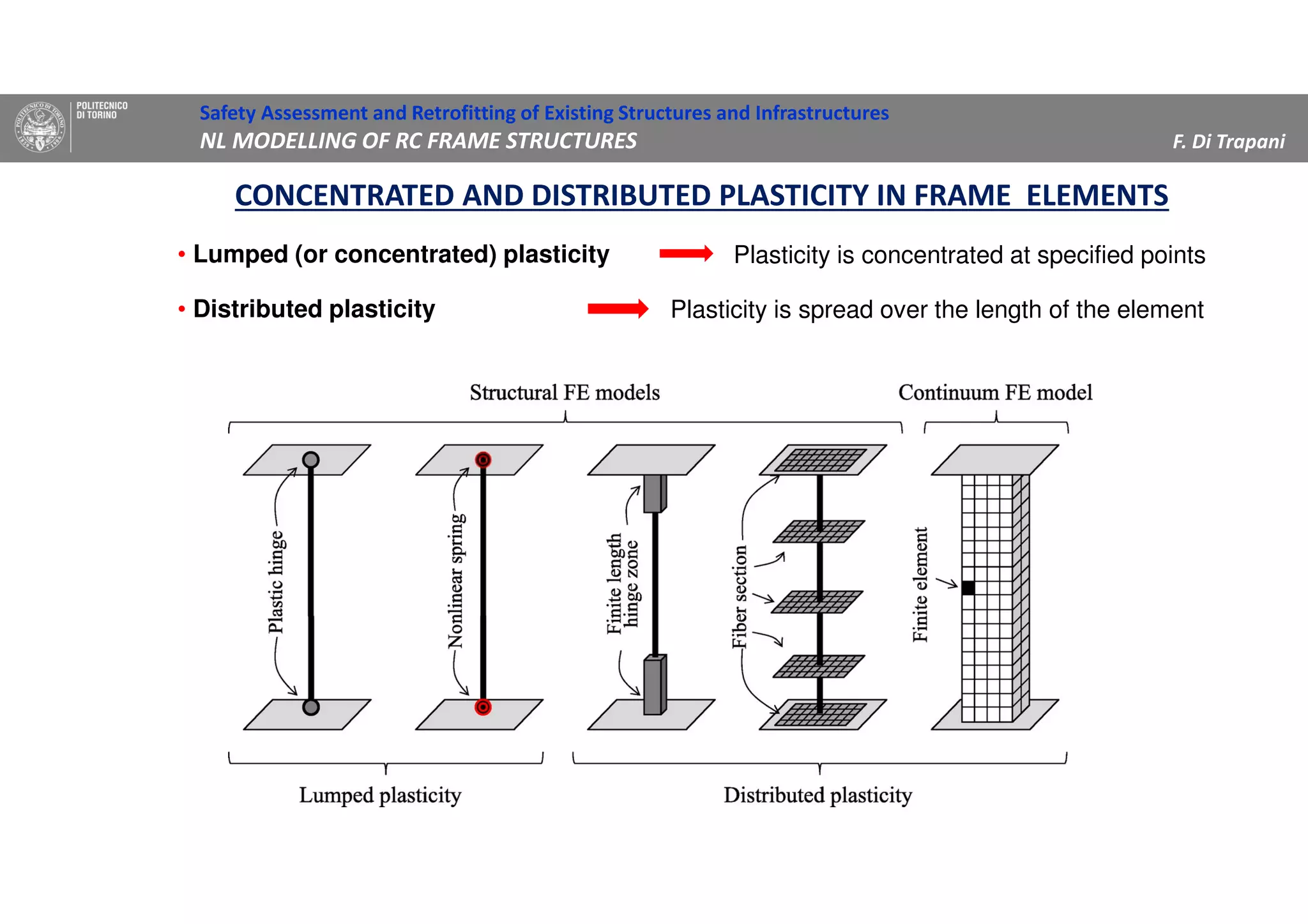
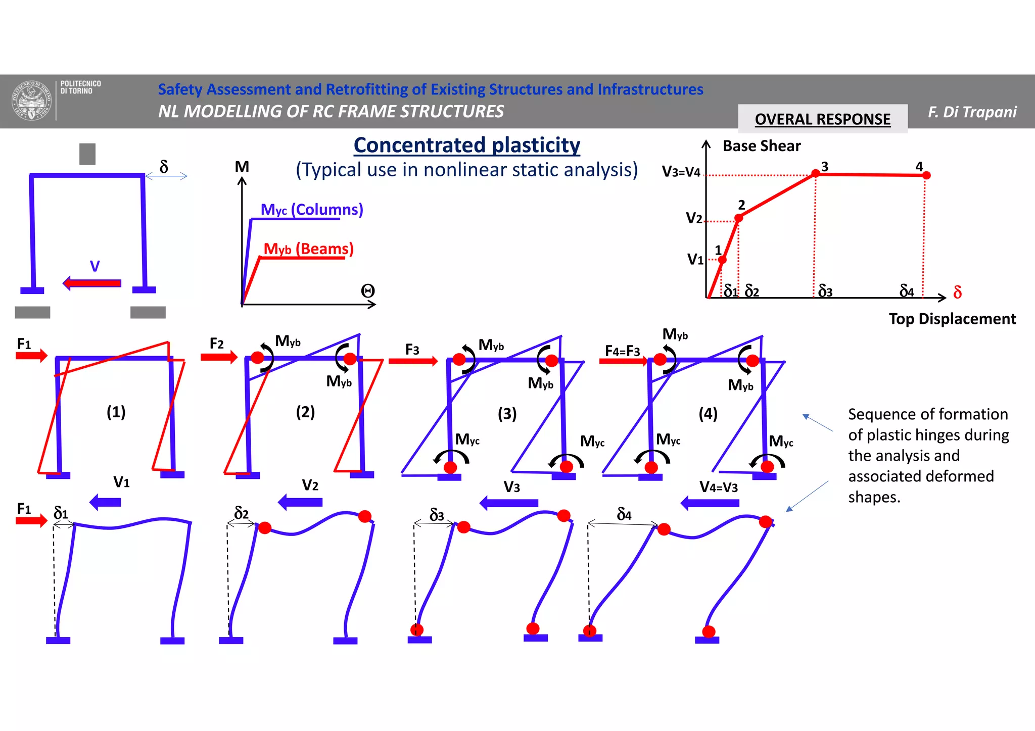
(2) Two methods for defining plastic hinge behavior are described: distributed plasticity, where plasticity is spread over the element length, and concentrated plasticity, where it is localized at specific points. Concentrated plasticity is commonly used for nonlinear static analysis of frames.
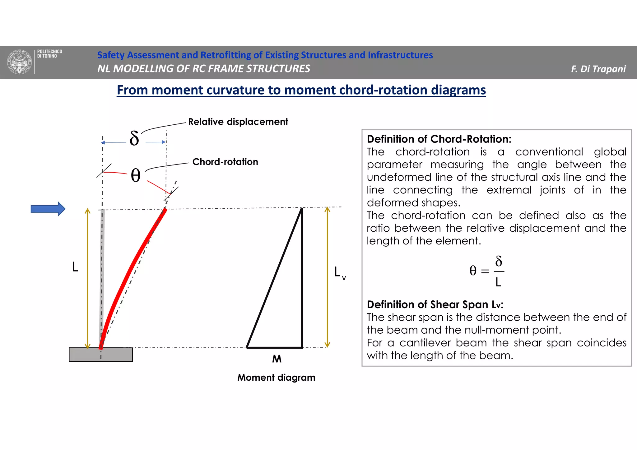
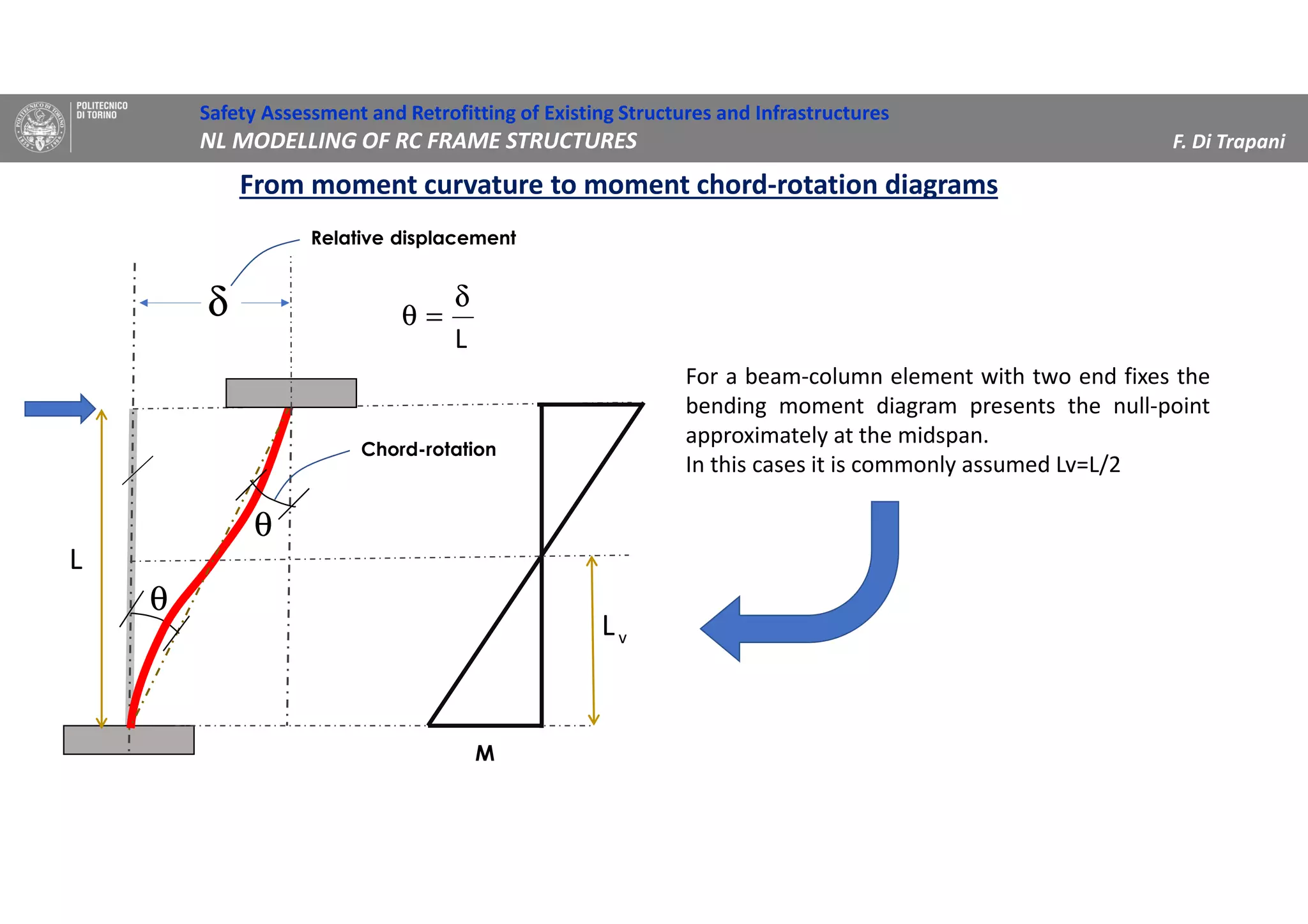
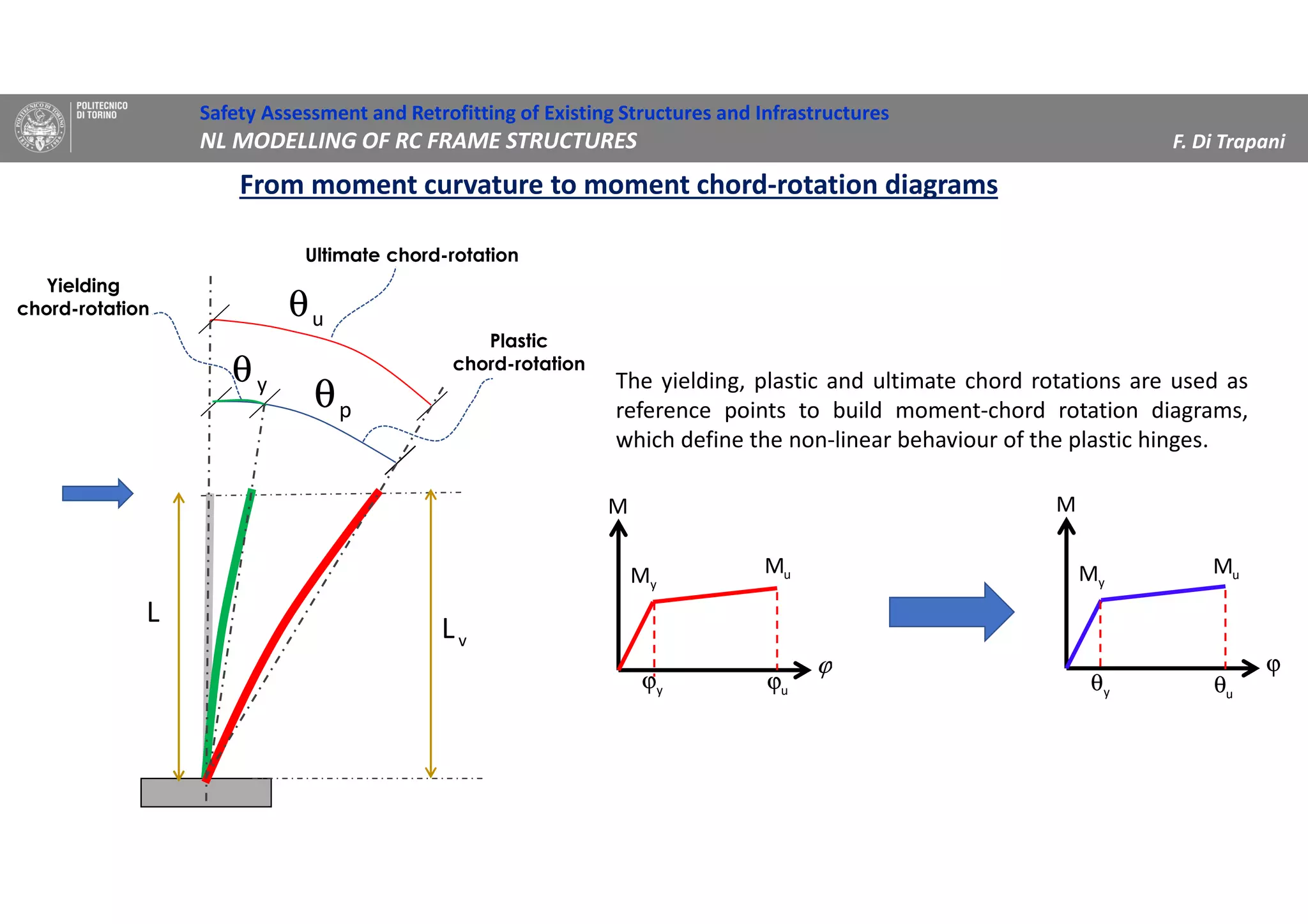
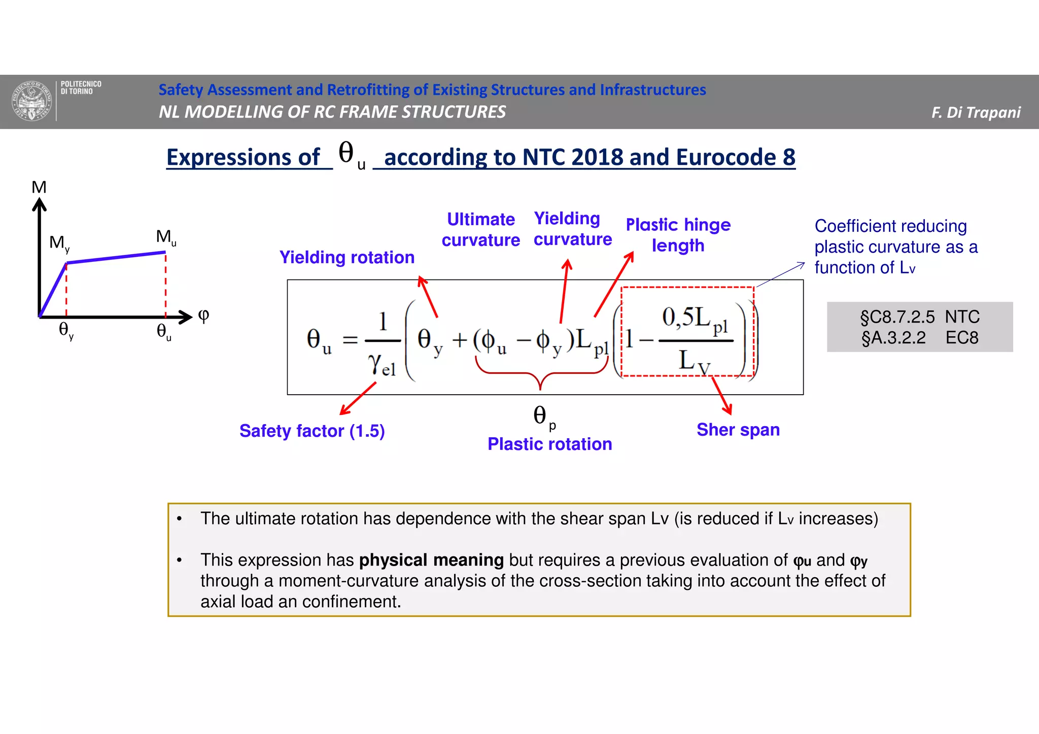
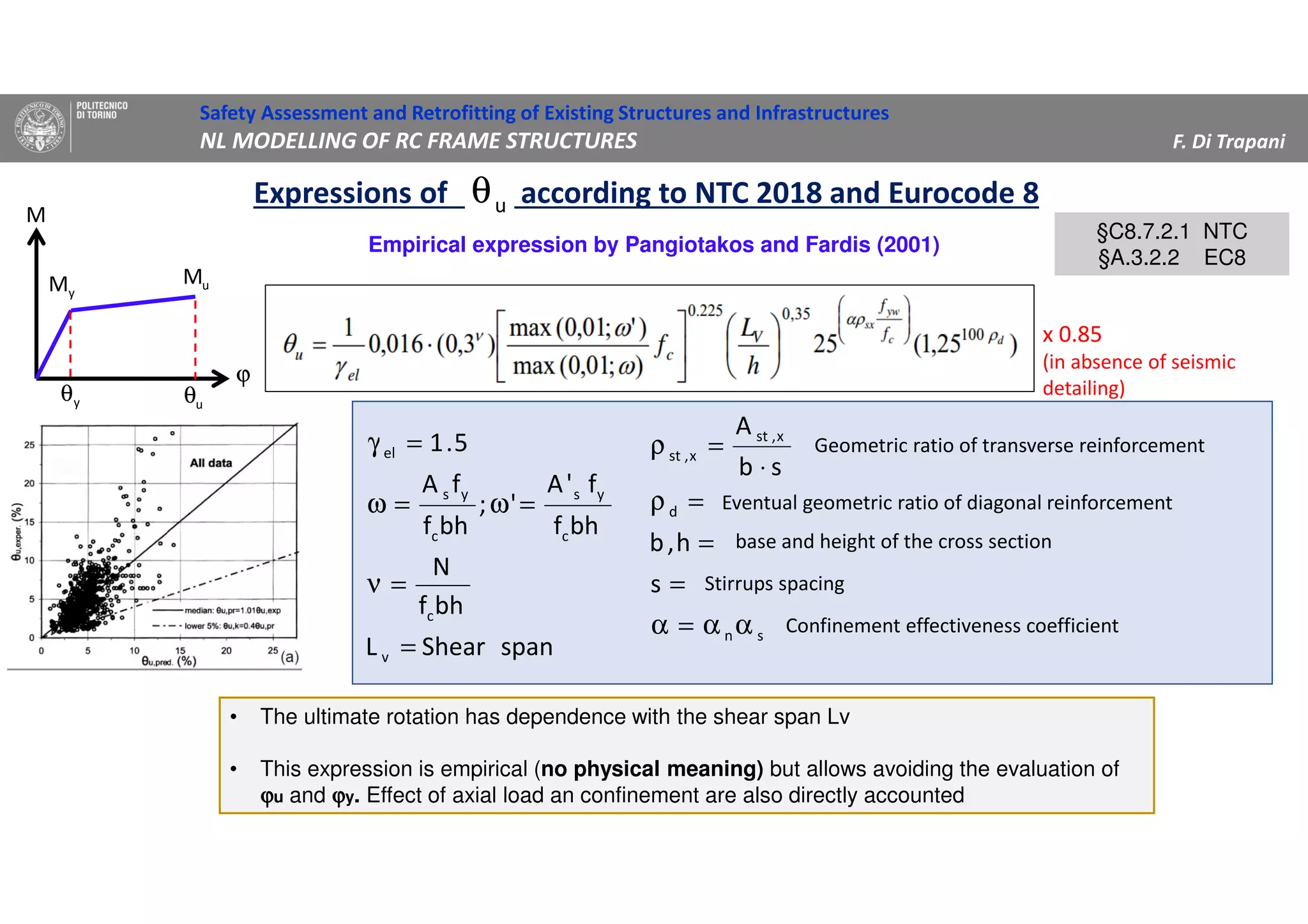
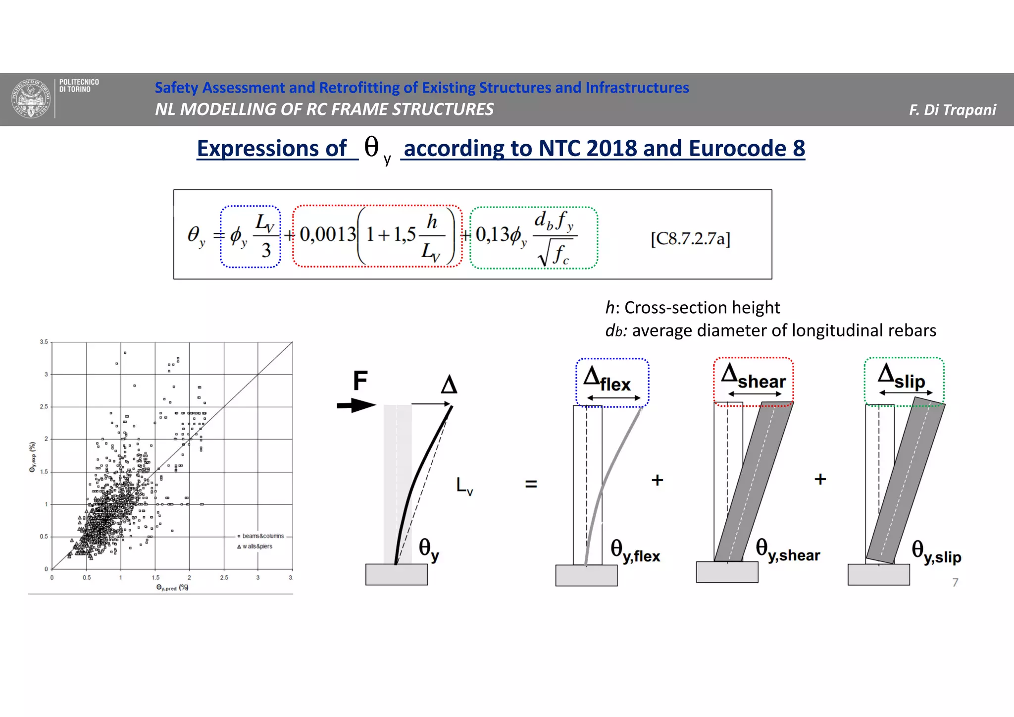
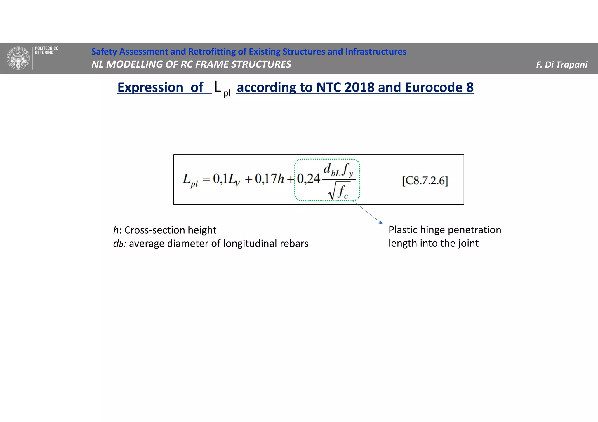
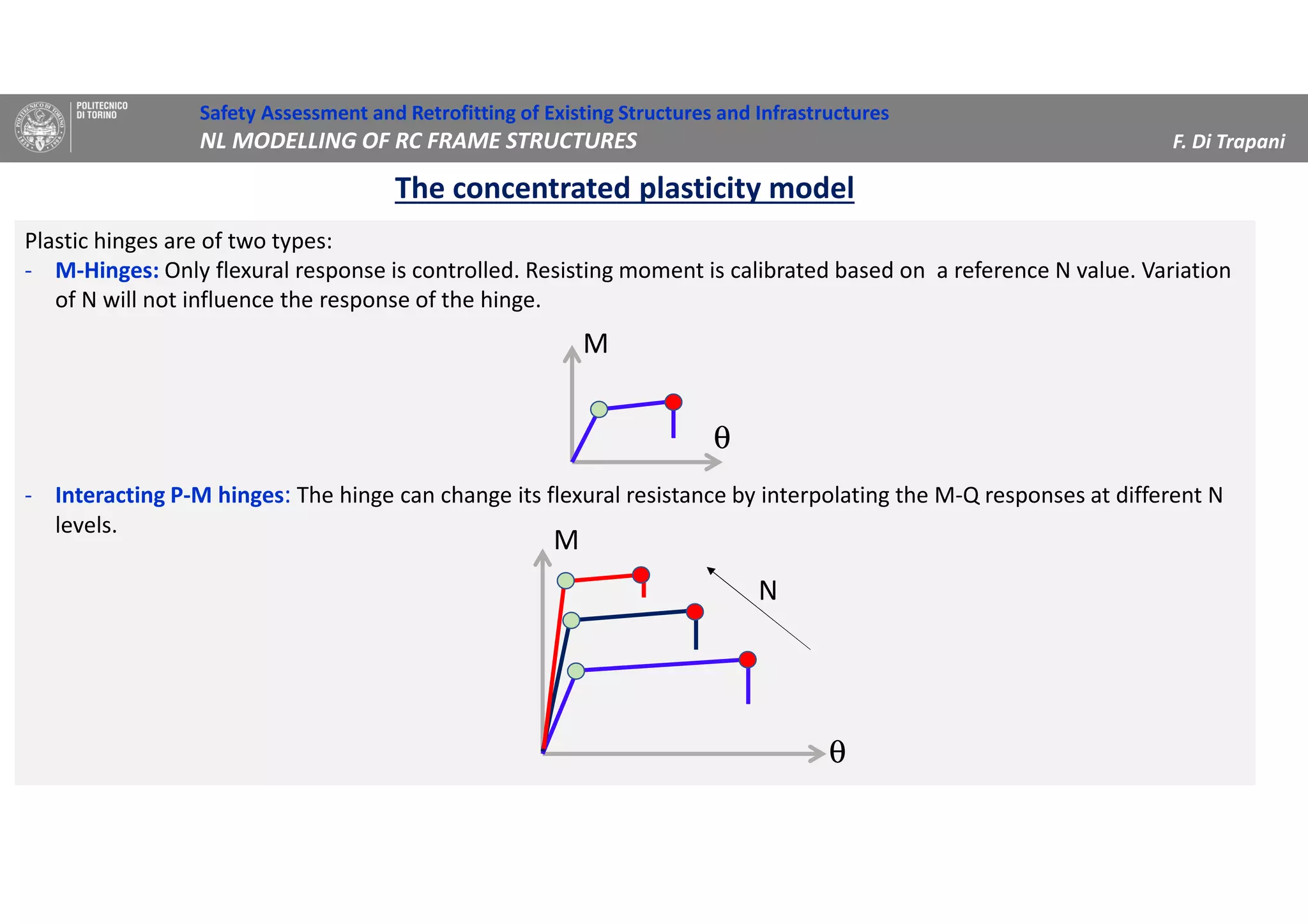
(3) Procedures for developing moment-rotation relationships for plastic hinges based on moment-curvature analysis or empirical equations are presented. These relationships define the inelastic behavior of components in the nonlinear analysis.
![EXERCISE 1
Moment – curvature analysis of the cross-section
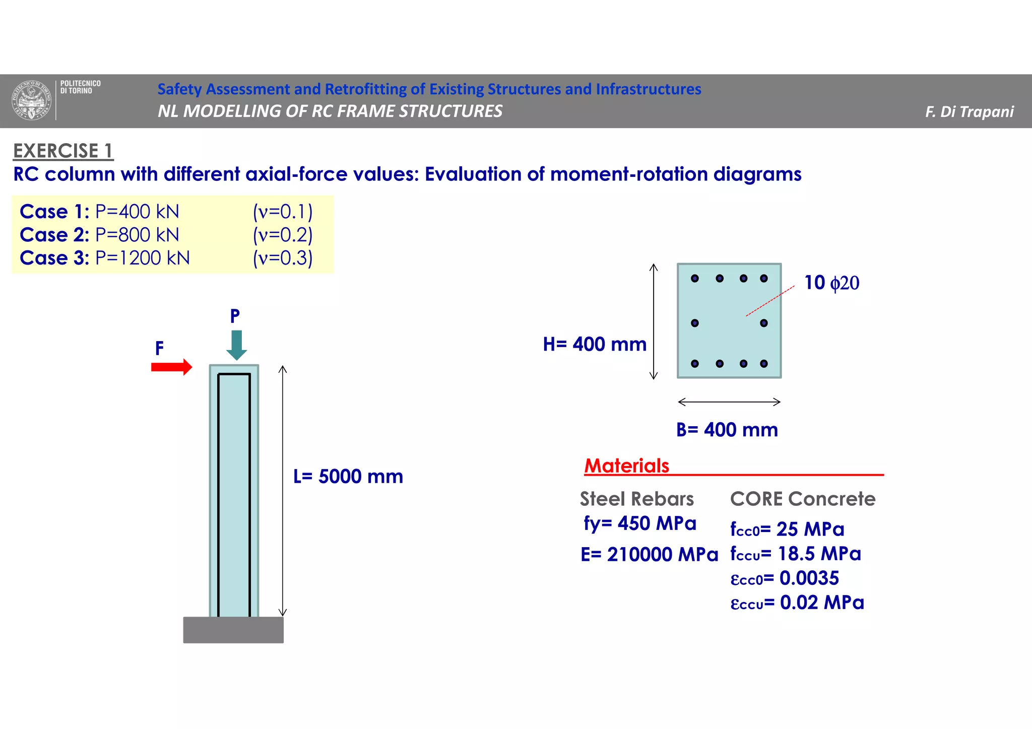
Case 1: P=400 kN (ν=0.1)
Case 2: P=800 kN (ν=0.2)
Case 3: P=1600 kN(ν=0.4)
0
50
100
150
200
250
300
350
400
0 0,00005 0,0001 0,00015 0,0002 0,00025
M[kNm]
φφφφ [1/mm]
M-φφφφ diagrams
N=400 kN
N=800 kN
N=1200 kN
N=400 kN N=800 kN N=1200 kN
φφφφu [1/mm] 0.0002244 0.0001442 0.00011
φφφφy [1/mm] 0.0000099 0.0000111 0.00001237
My (ideal.) [kNm] 276.9 312 340
Ultimate curvature
Yielding curvature
Idealized yielding moment
Evaluate …
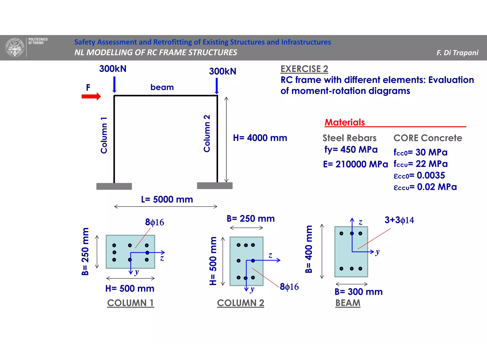
B= 400 mm
H= 400 mm
10 φ20φ20φ20φ20
Safety Assessment and Retrofitting of Existing Structures and Infrastructures
NL MODELLING OF RC FRAME STRUCTURES F. Di Trapani](https://image.slidesharecdn.com/5-200824114726/75/Nonlinear-modelling-of-RC-frame-structures-17-2048.jpg)
![EXERCISE 1
Evaluation of Moment – Rotation diagrams
Case 1: P=400 kN (ν=0.1)
Case 2: P=800 kN (ν=0.2)
Case 3: P=1600 kN(ν=0.4)
SECTION 400x400 Nu (kN) 4000
N v φφφφ u φφφφ y H B L L v fc dbl fy Lpl ΘΘΘΘ u ΘΘΘΘ y
(kN) - 1/mm 1/mm mm mm mm mm MPa mm MPa mm rad rad
400 0.10 0.00022 0.0000099 400 400 5000 5000 28 20 450 976.2 0.2091 0.0201
800 0.20 0.00014 0.00001111 400 400 5000 5000 28 20 450 976.2 0.1397 0.0224
1200 0.30 0.00011 0.00001237 400 400 5000 5000 28 20 450 976.2 0.1108 0.0248
0
50
100
150
200
250
300
350
0 0,05 0,1 0,15 0,2 0,25
M[kNm]
ΘΘΘΘ [rad]
M-ΘΘΘΘ diagrams
N=400 kN
N=800 kN
N=1200 kN
Safety Assessment and Retrofitting of Existing Structures and Infrastructures
NL MODELLING OF RC FRAME STRUCTURES F. Di Trapani](https://image.slidesharecdn.com/5-200824114726/75/Nonlinear-modelling-of-RC-frame-structures-18-2048.jpg)
![0
50
100
150
200
250
0 0,0001 0,0002 0,0003 0,0004 0,0005 0,0006
M[kNm]
φφφφ [1/mm]
M-φφφφ diagrams
Column 1
Column 2
Beam
Column 1 Column 2 Beam
N=400 kN N=800 kN N=1200 kN
φφφφu 0.0002059 0.0004 0.000524
φφφφy 0.00000697 0.00001578 0.0000075
My (idealized) 215 97 75
EXERCISE 2
Moment – curvature analysis of the cross-sections
Safety Assessment and Retrofitting of Existing Structures and Infrastructures
NL MODELLING OF RC FRAME STRUCTURES F. Di Trapani
N=300 kN N=300 kN N=0](https://image.slidesharecdn.com/5-200824114726/75/Nonlinear-modelling-of-RC-frame-structures-20-2048.jpg)
![0
50
100
150
200
250
0 0,05 0,1 0,15 0,2 0,25 0,3 0,35
M[kNm]
ΘΘΘΘ [rad]
M-ΘΘΘΘ diagrams
Column 1
Column 2
Beam
Nu N v (-) φφφφu φφφφy H B L Lv fc dbl N fi long fy Lpl ΘΘΘΘu ΘΘΘΘy My
kN kN (1/mm) (1/mm) (mm) (mm) (mm) (mm) (MPa) (mm) - (MPa) (mm) (mm) (mm) (kNm)
Column 1 3125 300 0.10 0.00021 0.00001 500 250 4000 2000 25 16 8 450 630.6 0.1134 0.0077 215
Column 2 3125 300 0.10 0.00040 0.00002 250 500 4000 2000 25 16 8 450 588.1 0.2078 0.015 97
Beam 3000 0 0.00 0.00052 0.00001 400 300 5000 2500 25 14 6 450 620.4 0.2898 0.0091 75
EXERCISE 2
Evaluation of Moment – Rotation diagrams
Safety Assessment and Retrofitting of Existing Structures and Infrastructures
NL MODELLING OF RC FRAME STRUCTURES F. Di Trapani](https://image.slidesharecdn.com/5-200824114726/75/Nonlinear-modelling-of-RC-frame-structures-21-2048.jpg)


![Part 1[Autosaved].pptx](https://cdn.slidesharecdn.com/ss_thumbnails/part1autosaved-221102081148-b5d4b037-thumbnail.jpg?width=640&height=640&fit=bounds)


