Downloaded 624 times


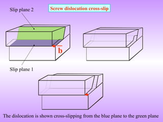
![Screw dislocation
[1]
[1] Bryan Baker
chemed.chem.purdue.edu/genchem/ topicreview/bp/materials/defects3.html -](https://image.slidesharecdn.com/crystalimperfectionsdislocations-141128112856-conversion-gate02/85/Crystal-imperfections-dislocations-20-320.jpg)


![Motion of a mixed dislocation
[1] http://www.tf.uni-kiel.de/matwis/amat/def_en/kap_5/backbone/r5_1_2.html
[1]
We are looking at the plane of the cut (sort of a semicircle centered in the lower left corner). Blue circles denote
atoms just below, red circles atoms just above the cut. Up on the right the dislocation is a pure edge dislocation
on the lower left it is pure screw. In between it is mixed. In the link this dislocation is shown moving in an
animated illustration.](https://image.slidesharecdn.com/crystalimperfectionsdislocations-141128112856-conversion-gate02/85/Crystal-imperfections-dislocations-25-320.jpg)


![Dissociation of dislocations
Consider the reaction:
2b → b + b
Change in energy:
G(2b)2/2 → 2[G(b)2/2]
G(b)2
Þ The reaction would be favorable](https://image.slidesharecdn.com/crystalimperfectionsdislocations-141128112856-conversion-gate02/85/Crystal-imperfections-dislocations-28-320.jpg)
![2
1 211
6
b = éë ùû
3
1 12 1
6
b = éë ùû
1
(111)
1 110
2
b = éë ùû
(111)
Slip plane
(111)
1 [110]
2
1 [121]
6
æ ö
çè ø¸ (111)
æ ö
çè ø¸ (111)
1 [211]
6
æ ö
çè ø¸ → +
b1
2 > (b2
2 + b3
2)
½ > ⅓
FCC
Shockley Partials
A
B
C
(111)
(111)
Some of the atoms are omitted for clarity
(111)
1 [12 1]
6
æ ö
çè ø¸
(111)
1 [211]
6
æ ö
çè ø¸](https://image.slidesharecdn.com/crystalimperfectionsdislocations-141128112856-conversion-gate02/85/Crystal-imperfections-dislocations-29-320.jpg)
![BCC Pure edge dislocation
Dislocation line vector
(110)
(110),(111)
1 [1 1 1]
2
æ ö
çè ø¸
1 [112]
2
æ ö
çè ø¸
(111)
(1 10)
Slip plane
Extra half plane
Burger’s vector
1 [111]
1 2 112
2
éë ùû
(110)](https://image.slidesharecdn.com/crystalimperfectionsdislocations-141128112856-conversion-gate02/85/Crystal-imperfections-dislocations-31-320.jpg)

![Slip systems
Crystal Slip plane(s) Slip direction
FCC {111} <110>
HCP (0001) <11`20>
BCC
Not close packed {110}, {112}, {123} [111]
No clear choice
Þ Wavy slip lines
Anisotropic](https://image.slidesharecdn.com/crystalimperfectionsdislocations-141128112856-conversion-gate02/85/Crystal-imperfections-dislocations-35-320.jpg)


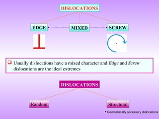
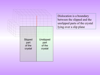
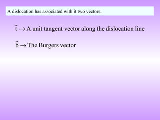
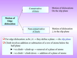
Dislocations are line defects in crystals that represent disrupted planes of atoms. They allow plastic deformation via slip along crystallographic planes and directions. A dislocation is characterized by its Burgers vector, which represents the lattice displacement caused by the dislocation and determines the direction of slip. The Burgers vector connects one lattice position to another. Dislocations lower the theoretical shear strength of crystals by several orders of magnitude, enabling plasticity. Their motion through glide and climb allows crystals to deform plastically under stress.