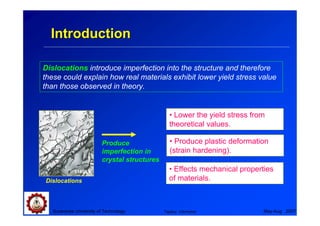
This chapter discusses dislocation theory and behavior in metals. Key topics covered include:
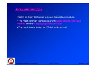
- Observation techniques for dislocations like etching and transmission electron microscopy
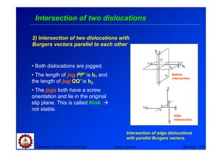
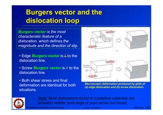
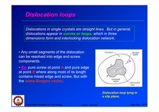
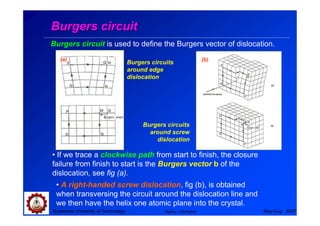
- Burgers vectors and dislocation loops that describe the geometry and movement of dislocations
- Dislocation behavior depends on the crystal structure, including dissociation in FCC into Shockley partials and easy cross-slip
- Dislocations interact through stress fields and forces, which influence deformation and strengthening mechanisms in metals

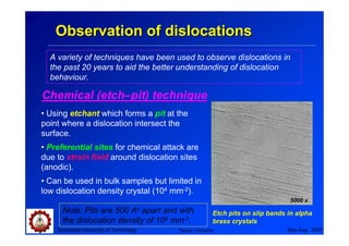
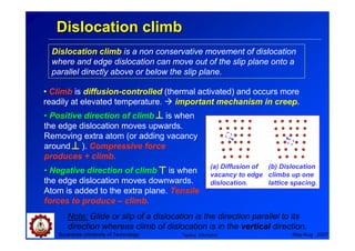
![Dislocations in FCC lattice
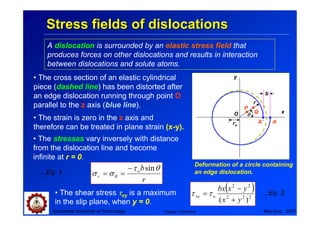
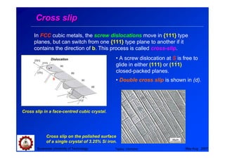
• Slip occurs in the FCC lattice on the {111} plane in the <110> direction
and with a Burgers vector (a/2)[110].
• The {111} planes are stacked on a close packed sequence ABCABC
and vector b = (ao/2)[101] defines one of the observed slip direction,
which can favourably energetically decompose into two partial
dislocations. Extended dislocation
b1 → b2 + b3 Faulted
region
ao a a
[101] → o [211] + o [112]
2 6 6
Shockley partials
Fully slipped No slip
This Shockley partials creates a
stacking fault ABCAC/ABC.
Dissociation of a dislocation to
Suranaree University of Technology Tapany Udomphol
two partial dislocations. May-Aug 2007](https://image.slidesharecdn.com/05dislocationtheory-111110101829-phpapp01/85/05-dislocation-theory-14-320.jpg)
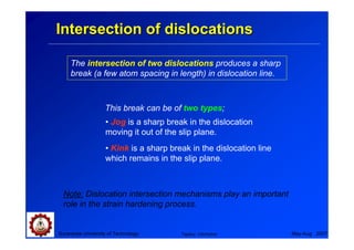
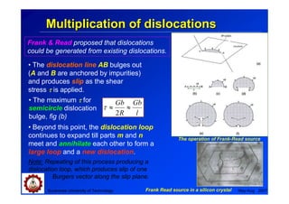
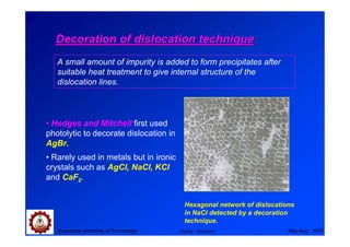
![Frank partial dislocations
Frank partial dislocations are
another type of partial dislocation in
FCC lattice, which provide
obstacles to the movement of other
dislocations.
Frank partial dislocation or sessile
dislocation.
• A set of (111) plane (viewed from the edge) has a missing middle A
plane with a Burgers vector (ao/3) [111] perpendicular to the central
stacking fault.
• Unlike perfect dislocation, Frank partial dislocation cannot move
by glide (sessile dislocation) but by diffusion of atom.
Suranaree University of Technology Tapany Udomphol May-Aug 2007](https://image.slidesharecdn.com/05dislocationtheory-111110101829-phpapp01/85/05-dislocation-theory-17-320.jpg)
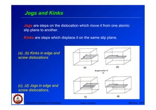
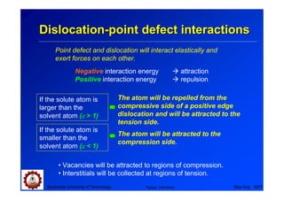
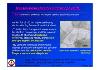
![Lomer-Cortrell barrier
Intersection of {111} plane during
duplex slip by glide of dislocations is
called Lomer-Cortrell barrier.
Ex: consider two perfect dislocations
lying in different {111} planes and
both parallel to the line of intersection
of the {111} plane.
Lomer-Cortrell barrier
ao a a
[101] + o [110] → o [011]
2 2 2
The new dislocation obtained has reduced energy.
Suranaree University of Technology Tapany Udomphol May-Aug 2007](https://image.slidesharecdn.com/05dislocationtheory-111110101829-phpapp01/85/05-dislocation-theory-18-320.jpg)
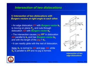
![Dislocations in HCP lattice
• Slip occurs in the HCP lattice on the basal (0001) plane in the
<1120> direction.
• The basal (0001) plane the close packed of a sequence ABABAB
and a Burgers vector b = (ao/3)[1120].
• Dislocations in the basal plane can reduce their energy by
dissociating into Shockley partials according to the reaction.
ao a a
[1120] → o [1010] + o [0110]
3 3 3
The stacking fault produced by this reaction lies in the basal
plane, and the extended dislocation which forms it is confined to
glide in this plane.
Suranaree University of Technology Tapany Udomphol May-Aug 2007](https://image.slidesharecdn.com/05dislocationtheory-111110101829-phpapp01/85/05-dislocation-theory-19-320.jpg)
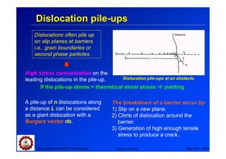
![Dislocations in BCC cubic lattice
• Slip occurs in the BCC lattice on {110}, {112}, {123} planes in the
<111> direction and a Burgers vector b = (ao/2)[111].
Cottrell has suggested a dislocation reaction which appears to cause
immobile dislocations. (ao/2[001] in iron) leading to a crack
nucleus formation mechanism for brittle fracture.
σ Applied stress
ao a
[111] + o [111] → a o [001] a
(101) Slip plane
2 2 [111]
2
(001) Cleavage plane
b = a[001]
the dislocation is immobile since
the (001) is not a close-packed slip a
[111] Cleavage knife crack of length c
2 for displacement nb
plane, the (001) plane is therefore (101) Slip plane
the cleavage plane when brittle
fracture occurs. σ
a
[111] + a [111] → a[001]
2 2
Slip on intersecting (110) plane.
Suranaree University of Technology Tapany Udomphol May-Aug 2007](https://image.slidesharecdn.com/05dislocationtheory-111110101829-phpapp01/85/05-dislocation-theory-20-320.jpg)