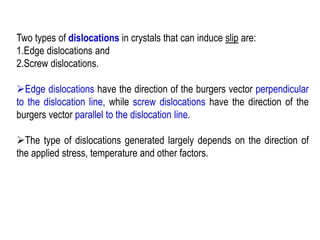
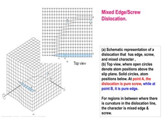
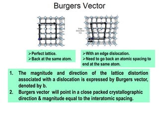
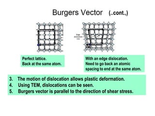
Download as PDF, PPTX

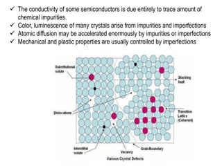
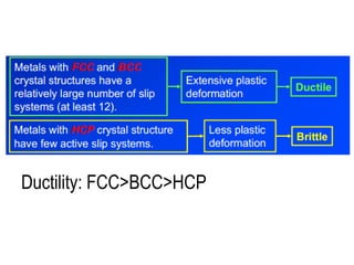
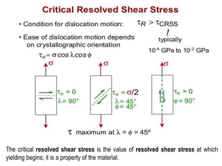
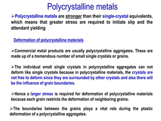

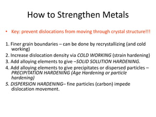

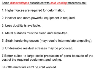

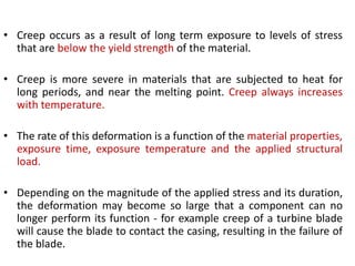

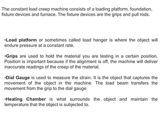
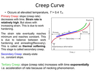


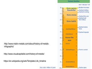
![Face centered cubic crystals
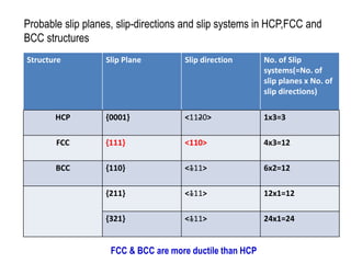
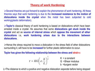
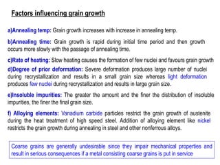
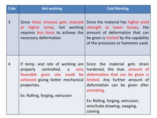
Slip in face centered cubic (fcc) crystals occurs along the
close packed plane. Specifically, the slip plane is of type
{111}, and the direction is of type <110>. In the diagram, the
specific plane and direction are (111) and [110], respectively.
Given the permutations of the slip plane types and direction
types, fcc crystals have 12 slip systems. In the fcc lattice,
the norm of the Burgers vector, b, can be calculated using the
following equation](https://image.slidesharecdn.com/unit-1ksr-170821161201/85/K-Srinivasulureddy-SNIST-Metallurgy-Material-Science-MMS-UNIT-1-158-320.jpg)
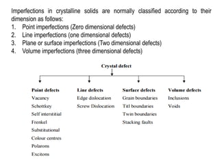
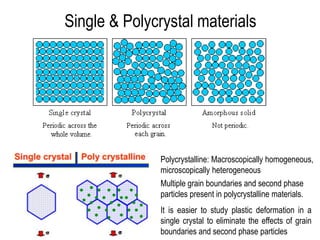
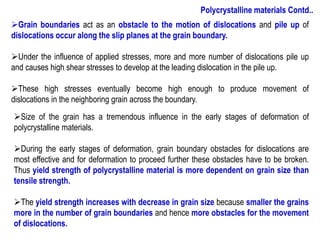
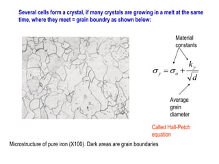
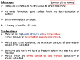
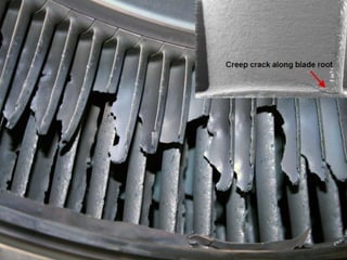
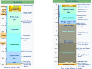
![Body centered cubic crystals(BCC)
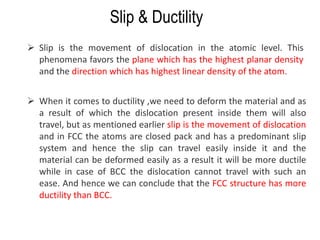
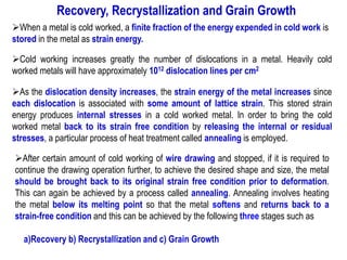
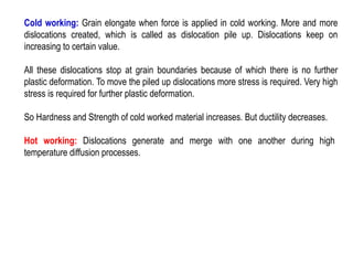
➢Slip in body-centered cubic (bcc) crystals occurs along the plane of
shortest Burgers vector. However, unlike fcc, there are no truly close-packed
planes in the bcc crystal structure. Thus, a slip system in bcc requires heat
to activate. Some bcc materials (e.g. α-Fe) can contain up to 48 slip systems.
➢There are 6 slip planes of type {110}, each with two <111> directions (12
systems). There are 24 {123} and 12 {112} planes each with one <111> direction
(36 systems, for a total of 48).
➢While the {123} and {112} planes are not exactly identical in activation energy to
{110}, they are so close in energy that for all intents and purposes they can be
treated as identical. In the diagram on the right the specific slip plane and direction
are (110) and [111], respectively](https://image.slidesharecdn.com/unit-1ksr-170821161201/85/K-Srinivasulureddy-SNIST-Metallurgy-Material-Science-MMS-UNIT-1-159-320.jpg)
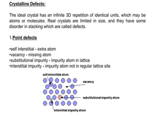
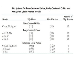
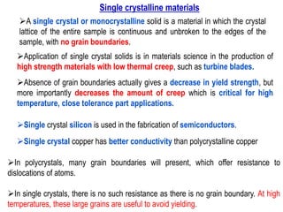
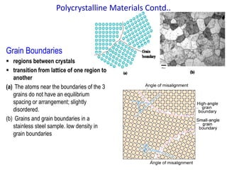
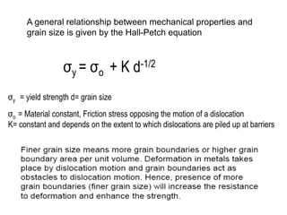
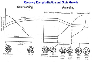
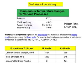
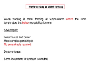
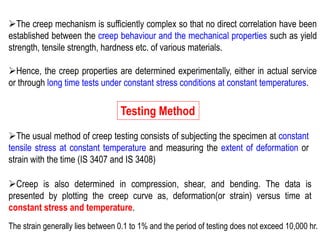
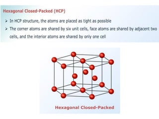
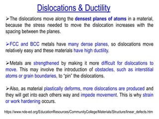
![The Hexagonal Close-Packed Crystal Structure (HCP)
(a) a reduced-sphere unit cell (a and c represent the short and long edge lengths,
respectively), and (b) an aggregate of many atoms.
In a close-packed structure the close packed directions are the directions in which
atoms are touching.
➢For a hcp structure the close packed directions are [100], [010] and [110] and their
negatives. Directions that are related by symmetry are represented using the notation
<UVW>. The close packed directions for hcp are then <100>.](https://image.slidesharecdn.com/unit-1ksr-170821161201/85/K-Srinivasulureddy-SNIST-Metallurgy-Material-Science-MMS-UNIT-1-160-320.jpg)

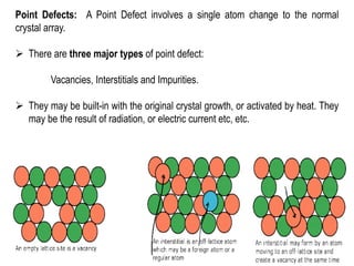
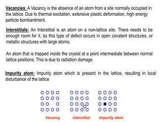
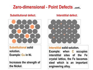
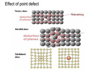
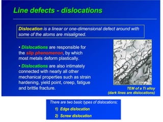
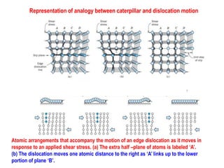
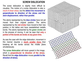
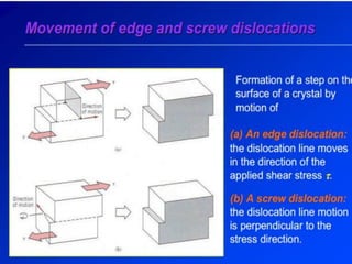
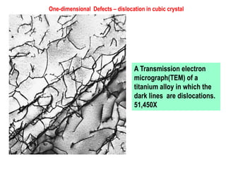
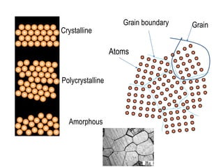
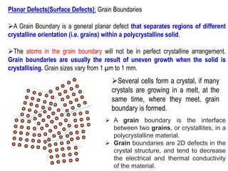
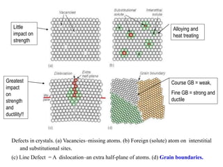
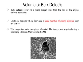
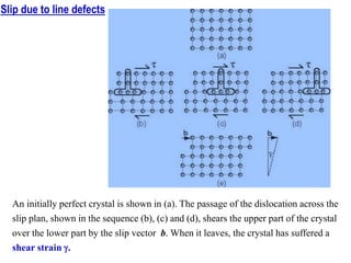
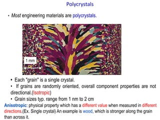
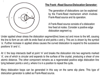
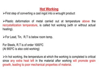
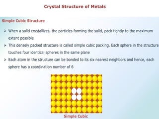
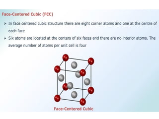
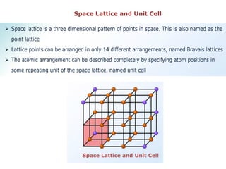
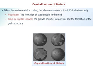
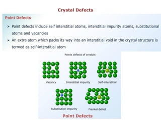
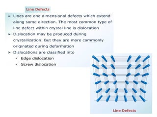
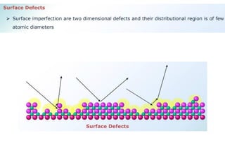
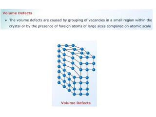
This document discusses various types of crystal defects including point defects, line defects, and planar defects. It defines point defects as zero-dimensional defects involving a single atom change, such as vacancies, interstitials, and impurities. Line defects are described as one-dimensional dislocations, including edge and screw dislocations. Planar defects are two-dimensional grain boundaries that separate crystalline regions with different orientations within a polycrystalline solid. The document explores how these defects influence material properties.


