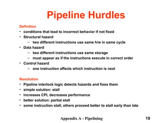
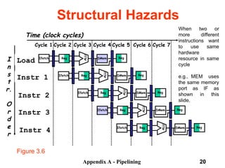
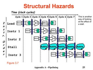
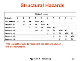
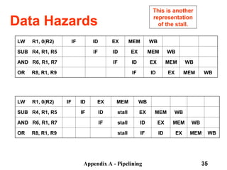
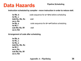
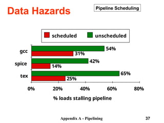
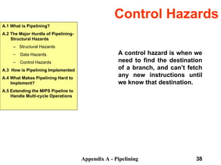
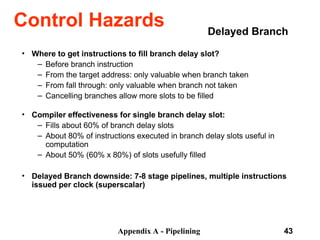
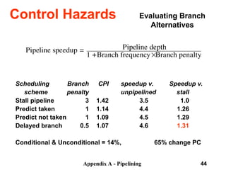
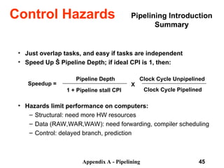
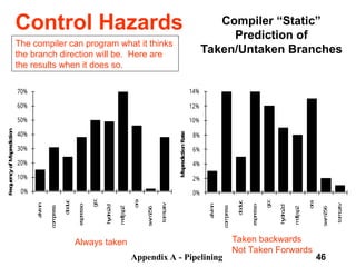
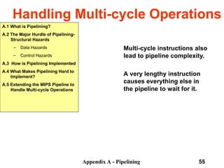
The document discusses pipelining in computer architecture, focusing on its definition, implementation, and associated hazards such as structural, data, and control hazards. It explains how pipelining enhances throughput while identifying challenges that arise from resource conflicts and data dependencies during execution. Additionally, the document presents examples illustrating the advantages and drawbacks of pipelining, with technical details pertinent to the MIPS architecture.
![Appendix A - Pipelining 11
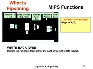
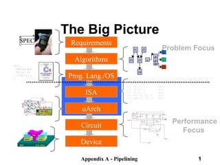
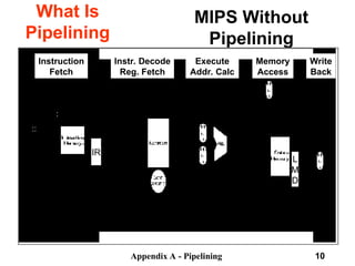
MIPS Functions
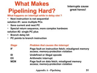
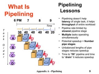
What Is
Pipelining
Memory
Access
Write
Back
Instruction
Fetch
Instr. Decode
Reg. Fetch
Execute
Addr.
Calc
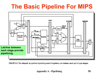
IR L
M
D
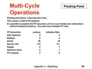
Instruction Fetch (IF):
Send out the PC and fetch the instruction from memory into the instruction
register (IR); increment the PC by 4 to address the next sequential
instruction.
IR holds the instruction that will be used in the next stage.
NPC holds the value of the next PC.
Passed To Next Stage
IR <- Mem[PC]
NPC <- PC + 4](https://image.slidesharecdn.com/pipelininglecture-240911085111-11c51967/85/Pipelining_Lecture-computer-Organisation-ppt-11-320.jpg)
![Appendix A - Pipelining 12
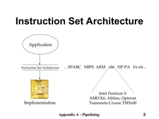
MIPS Functions
What Is
Pipelining
Memory
Access
Write
Back
Instruction
Fetch
Instr. Decode
Reg. Fetch
Execute
Addr.
Calc
IR L
M
D
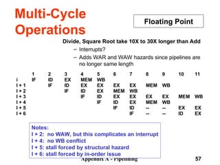
Instruction Decode/Register Fetch Cycle (ID):
Decode the instruction and access the register file to read the registers.
The outputs of the general purpose registers are read into two temporary
registers (A & B) for use in later clock cycles.
We extend the sign of the lower 16 bits of the Instruction Register.
Passed To Next Stage
A <- Regs[IR6..IR10];
B <- Regs[IR10..IR15];
Imm <- ((IR16) ##IR16-31](https://image.slidesharecdn.com/pipelininglecture-240911085111-11c51967/85/Pipelining_Lecture-computer-Organisation-ppt-12-320.jpg)
![Appendix A - Pipelining 14
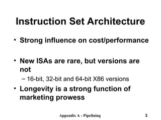
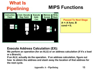
MIPS Functions
What Is
Pipelining
Memory
Access
Write
Back
Instruction
Fetch
Instr. Decode
Reg. Fetch
Execute
Addr.
Calc
IR L
M
D
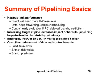
Passed To Next Stage
A = Mem[prev. B]
or
Mem[prev. B] = A
MEMORY ACCESS (MEM):
If this is an ALU, do nothing.
If a load or store, then access memory.](https://image.slidesharecdn.com/pipelininglecture-240911085111-11c51967/85/Pipelining_Lecture-computer-Organisation-ppt-14-320.jpg)