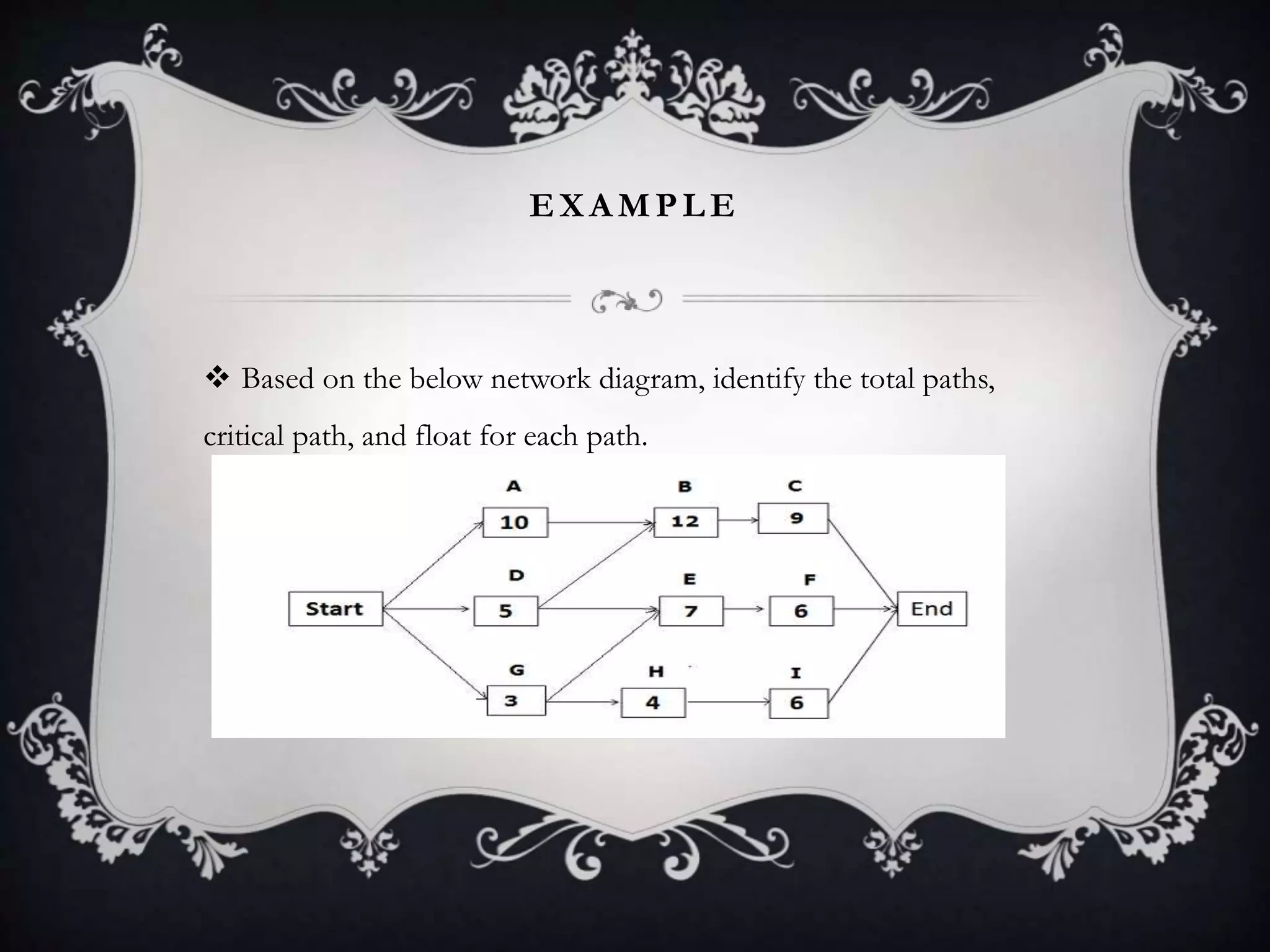
CPM NETWORK
Submitted by :
SURBHI JHA
TABLE OF CONTENTS
 Introduction
 History
 Steps in CPM Project Planning:
 Example
 CPM Project Risk ANALYSIS BY SIMULATION
 Why CONDUCT PROJECT RISK ANALYSIS
 Traditional Planning and Realism
 CPM Simulation Drives Risk Analysis Success
 Advantage
 Disadvantage
 Application
 Summary
 References
INTRODUCTION
 The critical path method (CPM) is a step-by-step project
management technique for process planning that defines critical and
non-critical tasks with the goal of preventing time-frame problems
and process bottlenecks. The CPM is ideally suited to projects
consisting of numerous activities that interact in a complex manner.
HISTORY
 The CPM was developed in the 1950s by DuPont, and was first
used in missile-defense construction projects. Since that time, the
CPM has been adapted to other fields including hardware and
software product research and development. Various computer
programs are available to help project managers use the CPM.
S T E P S I N C P M P RO J E C T P L A N N I N G :
 Specify the individual activities.
 Determine the sequence of those activities.
 Draw a network diagram.
 Estimate the completion time for each activity.
 Identify the critical path (the longest path through the network)
 Update the CPM diagram as the project progresses.
 1. Specify the individual activities.
From the Work Breakdown Structure, a listing can be made of all the activities in
the project. This listing can be used as the basis for adding sequence and duration
information in later steps.
 2. Determine the sequence of those activities.
Some activities are dependent upon the completion of others. A listing of the
immediate predecessors of each activity is useful for constructing the CPM network
diagram.
 3. Draw a network diagram.
Once the activities and their sequencing have been defined, the CPM diagram can
be drawn. CPM originally was developed as an activity on node (AON) network,
but some project planners prefer to specify the activities on the arcs.
 4. Estimate the completion time for each activity.
The time required to complete each activity can be estimated using past experience
or the estimates of knowledgeable persons. CPM is a deterministic model that does
not take into account variation in the completion time, so only one number can be
used for an activity’s time estimate.
 5. Identify the critical path
The critical path is the longest-duration path through the network. The significance
of the critical path is that the activities that lie on it cannot be delayed without
delaying the project. Because of its impact on the entire project, critical path
analysis is an important aspect of project planning.
T H E C R I T I C A L PA T H C A N B E I D E N T I F I E D B Y
D E T E R M I N I N G T H E F O L L O W I N G F O U R PA R A M E T E R S
F O R E A C H A C T I V I T Y :
 ES – earliest start time: the earliest time at which an activity can begin given that its predecessor activities
must be completed first.
 EF – earliest finish time, equal to the earliest start time for the activity plus the time required to complete the
activity.
 LF – latest finish time: the latest time at which an activity can be completed without delaying the project.
 LS – latest start time, equal to the latest finish time minus the time required to complete the activity.
The slack or float time for an activity is the time between the earliest and latest start time, or between the earliest
and latest finish time. Slack is the amount of time that an activity can be delayed past its earliest start or earliest
finish without delaying the project.
 The critical path is the path through the project network in which
none of the activities have slack, that is, the path for which LS=ES
and LF=EF for all activities in the path. A delay in the critical path
delays the project. Similarly, to accelerate the project it is necessary to
reduce the total time required for the activities in the critical path.
 6. Update CPM diagram
As the project progresses, the actual task completion times will be
known and the diagram can be updated to include this
information. A new critical path may emerge, and structural changes
may be made in the network if project requirements change
T O U S E C P M , C O M P L E T E T H E F O L L O W I N G S T E P S :
 Forward Pass:
Use network diagram & working from left to right: Calculate Early finish & Early
start.
 Backward Pass:
Use network diagram & working from right to left: Calculate late finish & late start.
 Float:
Subtracting early start from late start.
Subtracting early finish from late finish.
EXA MPLE
 Based on the below network diagram, identify the total paths,
critical path, and float for each path.
 The above network diagram has five paths; the paths and their duration are as
follows:
 Start -> A -> B -> C-> End, duration: 31 days.
 Start ->D -> E ->F -> End, duration: 18 days.
 Start -> D -> B -> C -> End, duration: 26 days.
 Start -> G ->H ->I -> End, duration: 13 days.
 Start -> G -> E ->F -> End, duration: 16 days.
 Since the duration of the first path is the longest, it is the critical path. The float on
the critical path is zero.
 The float for the second path “Start ->D -> E ->F -> End” = duration of the
critical path – duration of the path “Start ->D -> E ->F -> End”
 = 31 – 18 = 13
 Hence, the float for the second path is 13 days.
 Using the same process, we can calculate the float for other paths
as well.
 Float for the third path = 31 – 26 = 5 days.
Float for the fourth path = 31 – 13 = 18 days.
Float for the fifth path = 31 – 16 = 15 days.
 Calculate Early Start (ES), Early Finish (EF), Late Start (LS), and Late Finish (LF)
We have identified the critical path, and the duration of the other paths, it’s time to move on to
more advanced calculations, Early Start, Early Finish, Late Start and Late Finish.
 Calculating Early Start (ES) and Early Finish (EF)
 To calculate the Early Start and Early Finish dates, we use forward pass; we will start from
the beginning and proceed to the end.
 Early Start (ES) for the first activity on any path will be 1, because no activity can be started
before the first day. The start point for any activity or step along the path is the end point of the
predecessor activity on the path plus one.
 The formula used for calculating Early Start and Early Finish dates.
 Early Start of the activity = Early Finish of predecessor activity + 1
 Early Finish of the activity = Activity duration + Early Start of activity – 1
E A R L Y S TA R T A N D E A R L Y F I N I S H D A T E S F O R T H E
PA T H S TA R T - > A - > B - > C - > E N D
 Early Start of activity A = 1 (Since this is the first activity of the path)
 Early Finish of activity A = ES of activity A + activity duration – 1
= 1 + 10 – 1 = 10
 Early Start of activity B = EF of predecessor activity + 1
= 10 +1 = 11
 Early Finish of activity B = ES of activity B + activity duration – 1
= 11 + 12 – 1 = 22
 Early Start of activity C = EF of predecessor activity + 1
= 22 +1 = 23
 Early Finish of activity C = ES of activity C + activity duration – 1
= 23 + 9 – 1 = 31
E A R LY S TA R T A N D E A R LY F I N I S H DA T E S F O R
T H E PA T H S TA R T - > D - > E - > F - > E N D
 Early Start of activity D = 1 (Since this is the first activity of the path)
 Early Finish of activity D = 1 + 5 – 1 = 5
 Early Start of activity E = EF of predecessor activity + 1
 Since the Activity E has two predecessor activities, which one will you select? You will
select the activity with the greater Early Finish date. Early Finish of activity D is 5, and
Early Finish of activity G is 3 (we will calculate it later).
 Therefore, we will select the Early Finish of activity D to find the Early Start of
activity E.
 Early Start of activity E = EF of predecessor activity + 1
= 5 + 1 = 6
 Early Finish of activity E = 6 + 7 – 1 = 12
 Early Start of activity F = 12 + 1 = 13
 Early Finish of activity F = 13 + 6 -1 = 18
E A R L Y S T A R T A N D E A R L Y F I N I S H D A T E S F O R T H E P A T H
S T A R T - > G - > H - > I - > E N D
 Early Start of activity G = 1 (Since this is the first activity of the path)
Early Finish of activity G = 1 + 3 – 1 = 3
 Early Start of activity H = 3 + 1 = 4
Early Finish of activity H = 4 + 4 – 1 = 7
 Early Start of activity I = 7 +1 = 8
Early Finish of activity I = 8 + 6 – 1 = 13
C A L C U L A T I N G L A T E S TA R T ( L S ) A N D L A T E
F I N I S H ( L F )
 We have calculated Early Start and Early Finish dates of all activities. Now it is time to
calculate the Late Start and Late Finish dates.
 Late Finish of the last activity in any path will be the same as the Last Finish of the last
activity on the critical path, because you cannot continue any activity once the project is
completed.
 The formula used for Late Start and Late Finish dates:
 Late Start of Activity = Late Finish of activity – activity duration + 1
 Late Finish of Activity = Late Start of successor activity – 1
 To calculate the Late Start and Late Finish, we use backward pass; i.e. we will start from the
last activity and move back towards the first activity.
L A T E S TA R T A N D L A T E F I N I S H DA T E S F O R
T H E PA T H S TA R T - > A - > B - > C - > E N D
 On a critical path, Early Start, and Early Finish dates will be the
same as Late Start and Late Finish dates.
L A T E S TA R T A N D L A T E F I N I S H DA T E S F O R
T H E PA T H S TA R T - > D - > E - > F - > E N D
 Late Finish of activity F = 31 (because you cannot allow any activity to cross the project completion date)
 Late Start of activity F = LF of activity F – activity duration + 1
= 31 – 6 +1 = 26
 Late Finish of activity E = LS of successor activity – 1
= LS of activity F – 1
= 26 – 1 = 25
 Late Start of Activity E = LF of activity E – activity duration + 1
= 25 – 7 + 1 = 19
 Late Finish of activity D = LS of successor activity – 1
 If you look at the network diagram, you will notice that activity D has two successor activities, B and E. So, which
activity will you select?
 You will select the activity with the earlier(least) Late Start date. Here, Late Start of activity B is 11, and Late Start of
activity E is 19.
 Therefore, you will select activity B which has the earlier Late Start date.
 Hence,
 Late Finish of activity D = LS of activity B – 1
= 11 – 1 = 10
 Late Start of Activity D = LF of activity D – activity duration + 1
= 10 – 5 + 1 = 6
L A T E S TA R T A N D L A T E F I N I S H D A T E S F O R T H E
PA T H S TA R T - > G - > H - > I - > E N D
 Late Finish of activity I = 31 (because you cannot allow any activity to
cross the project completion date)
Late Start of activity I = 31 – 6 + 1 = 26
 Late Finish of activity H = 26 – 1 = 25
Late Start of activity H = 25 – 4 + 1 = 22
 Late Finish of Activity G = 19 – 1= 18 (we will choose the late start of
activity E, not activity H, because the Late Start of activity E is earlier than the
Late Start of activity H)
 Late Start of activity G = 18 – 3 + 1
= 16
C A L C U L A T E T H E F R E E F L OA T
 The formula for the Free Float is:
 Free Float = ES of next activity – EF of current activity – 1
C P M P R O J E C T R I S K A N A L Y S I S B Y S I M U L A T I O N
 Project risk analysis has always been as challenging and complicated
as valuable and mission-critical. The information a team gathers while
analyzing risks is valuable as long as it helps the team perceive true risk
exposure and reduce the key drivers. The impact of uncertainties and risk
events can jeopardize project schedule and push critical path completion
dates out of alignment with project goals. A simulation-driven risk
analysis in critical path management (CPM) gives the team a true sense of
exposure. Risk models let ensure realistic CPM scheduling.
W H Y C O N D U C T P RO J E C T R I S K A N A LY S I S
 The purpose of conducting risk analysis is to gain a deeper
insight into the potential impact uncertainty and risk events will have
on a project within its life-cycle, from conceptualization and
development through to delivery and evaluation.
T R A D I T I O NA L P L A N N I N G A N D R E A L I S M
 If employing traditional planning, we need to consider that there should be
finite durations and costs for the project. This approach often works fine for short-
term unsophisticated endeavors. However, these finite values become unrealistic
when we forecast the schedule, cost and other key contracts for several or more
years ahead. Even our best-made prediction can’t be 100% reliable and realistic
because of inevitable long-term changes in rates, quantities, scope, human
resources, and other variables. Traditional planning fails at long distance, and the
situation becomes more challenging when the potential presence of threats and
opportunities (risk events) are not taken into account.
C P M S I M U L AT I O N D R I V E S R I S K A N A LY S I S
S U C C E S S
 When you begin to deal with all these uncertainties and risk events
you wonder how to best budget and schedule your project
activities. Critical path management gives you the right solution:
you can combine everything into a network in which dependency
determines the order of execution. And you can then manage the
critical path to ensure your project won’t take longer than expected.
ADVANTAGES OF CPM
 It shows the graphical view of the project.
 It discovers and makes dependencies visible.
 It helps in project planning, scheduling, and controlling.
 It helps in contingency planning.
 It shows the critical path, and identifies critical activities requiring special
attention.
 It helps you assign the float to activities and flexibility to float activities.
 It shows you where you need to take action to bring project back on track.
CPM LIMITATIONS
 Because the critical path method is an optimal planning tool, it always assumes that all
resources are available for the project at all times.
 It does not consider resource dependencies.
 There are chances of misusing float or slack.
 Less attention on non-critical activities, though sometimes they may also become
critical activities.
 Projects based on the critical path often fail to be completed within the approved
time duration.
 To overcome these shortcomings of the critical path, the critical chain method was
developed. In the critical chain method resource constraints are also taken into
consideration while developing the network diagram.
SUMMARY
 he critical path method has helped many project managers develop and
manage their schedule. In the critical path method, you will draw a
network diagram with multiple paths. The path with the longest duration
is known as the critical path. During your project execution your main
emphasis will be on this path, because this is the longest duration path
and the duration of this path will be duration of the project.
 As a project manager you have to keep an eye on your network
diagram and take prompt corrective action whenever necessary.
REFERENCES
 http://www.netmba.com/operations/project/cpm/
 http://www.mymanagementguide.com/cpm-project-risk-analysis-
simulation-modeling/
 https://whatis.techtarget.com/definition/critical-path-method-
CPM
 https://pmstudycircle.com/2014/01/critical-path-method-cpm-
in-project-management/
CPM NETWORK

CPM NETWORK

  • 1.
  • 2.
    TABLE OF CONTENTS Introduction  History  Steps in CPM Project Planning:  Example  CPM Project Risk ANALYSIS BY SIMULATION  Why CONDUCT PROJECT RISK ANALYSIS  Traditional Planning and Realism  CPM Simulation Drives Risk Analysis Success  Advantage  Disadvantage  Application  Summary  References
  • 3.
    INTRODUCTION  The criticalpath method (CPM) is a step-by-step project management technique for process planning that defines critical and non-critical tasks with the goal of preventing time-frame problems and process bottlenecks. The CPM is ideally suited to projects consisting of numerous activities that interact in a complex manner.
  • 4.
    HISTORY  The CPMwas developed in the 1950s by DuPont, and was first used in missile-defense construction projects. Since that time, the CPM has been adapted to other fields including hardware and software product research and development. Various computer programs are available to help project managers use the CPM.
  • 5.
    S T EP S I N C P M P RO J E C T P L A N N I N G :  Specify the individual activities.  Determine the sequence of those activities.  Draw a network diagram.  Estimate the completion time for each activity.  Identify the critical path (the longest path through the network)  Update the CPM diagram as the project progresses.
  • 6.
     1. Specifythe individual activities. From the Work Breakdown Structure, a listing can be made of all the activities in the project. This listing can be used as the basis for adding sequence and duration information in later steps.  2. Determine the sequence of those activities. Some activities are dependent upon the completion of others. A listing of the immediate predecessors of each activity is useful for constructing the CPM network diagram.  3. Draw a network diagram. Once the activities and their sequencing have been defined, the CPM diagram can be drawn. CPM originally was developed as an activity on node (AON) network, but some project planners prefer to specify the activities on the arcs.
  • 7.
     4. Estimatethe completion time for each activity. The time required to complete each activity can be estimated using past experience or the estimates of knowledgeable persons. CPM is a deterministic model that does not take into account variation in the completion time, so only one number can be used for an activity’s time estimate.  5. Identify the critical path The critical path is the longest-duration path through the network. The significance of the critical path is that the activities that lie on it cannot be delayed without delaying the project. Because of its impact on the entire project, critical path analysis is an important aspect of project planning.
  • 8.
    T H EC R I T I C A L PA T H C A N B E I D E N T I F I E D B Y D E T E R M I N I N G T H E F O L L O W I N G F O U R PA R A M E T E R S F O R E A C H A C T I V I T Y :  ES – earliest start time: the earliest time at which an activity can begin given that its predecessor activities must be completed first.  EF – earliest finish time, equal to the earliest start time for the activity plus the time required to complete the activity.  LF – latest finish time: the latest time at which an activity can be completed without delaying the project.  LS – latest start time, equal to the latest finish time minus the time required to complete the activity. The slack or float time for an activity is the time between the earliest and latest start time, or between the earliest and latest finish time. Slack is the amount of time that an activity can be delayed past its earliest start or earliest finish without delaying the project.
  • 9.
     The criticalpath is the path through the project network in which none of the activities have slack, that is, the path for which LS=ES and LF=EF for all activities in the path. A delay in the critical path delays the project. Similarly, to accelerate the project it is necessary to reduce the total time required for the activities in the critical path.  6. Update CPM diagram As the project progresses, the actual task completion times will be known and the diagram can be updated to include this information. A new critical path may emerge, and structural changes may be made in the network if project requirements change
  • 10.
    T O US E C P M , C O M P L E T E T H E F O L L O W I N G S T E P S :  Forward Pass: Use network diagram & working from left to right: Calculate Early finish & Early start.  Backward Pass: Use network diagram & working from right to left: Calculate late finish & late start.  Float: Subtracting early start from late start. Subtracting early finish from late finish.
  • 11.
    EXA MPLE  Basedon the below network diagram, identify the total paths, critical path, and float for each path.
  • 12.
     The abovenetwork diagram has five paths; the paths and their duration are as follows:  Start -> A -> B -> C-> End, duration: 31 days.  Start ->D -> E ->F -> End, duration: 18 days.  Start -> D -> B -> C -> End, duration: 26 days.  Start -> G ->H ->I -> End, duration: 13 days.  Start -> G -> E ->F -> End, duration: 16 days.  Since the duration of the first path is the longest, it is the critical path. The float on the critical path is zero.  The float for the second path “Start ->D -> E ->F -> End” = duration of the critical path – duration of the path “Start ->D -> E ->F -> End”  = 31 – 18 = 13  Hence, the float for the second path is 13 days.
  • 13.
     Using thesame process, we can calculate the float for other paths as well.  Float for the third path = 31 – 26 = 5 days. Float for the fourth path = 31 – 13 = 18 days. Float for the fifth path = 31 – 16 = 15 days.
  • 14.
     Calculate EarlyStart (ES), Early Finish (EF), Late Start (LS), and Late Finish (LF) We have identified the critical path, and the duration of the other paths, it’s time to move on to more advanced calculations, Early Start, Early Finish, Late Start and Late Finish.  Calculating Early Start (ES) and Early Finish (EF)  To calculate the Early Start and Early Finish dates, we use forward pass; we will start from the beginning and proceed to the end.  Early Start (ES) for the first activity on any path will be 1, because no activity can be started before the first day. The start point for any activity or step along the path is the end point of the predecessor activity on the path plus one.  The formula used for calculating Early Start and Early Finish dates.  Early Start of the activity = Early Finish of predecessor activity + 1  Early Finish of the activity = Activity duration + Early Start of activity – 1
  • 15.
    E A RL Y S TA R T A N D E A R L Y F I N I S H D A T E S F O R T H E PA T H S TA R T - > A - > B - > C - > E N D
  • 16.
     Early Startof activity A = 1 (Since this is the first activity of the path)  Early Finish of activity A = ES of activity A + activity duration – 1 = 1 + 10 – 1 = 10  Early Start of activity B = EF of predecessor activity + 1 = 10 +1 = 11  Early Finish of activity B = ES of activity B + activity duration – 1 = 11 + 12 – 1 = 22  Early Start of activity C = EF of predecessor activity + 1 = 22 +1 = 23  Early Finish of activity C = ES of activity C + activity duration – 1 = 23 + 9 – 1 = 31
  • 17.
    E A RLY S TA R T A N D E A R LY F I N I S H DA T E S F O R T H E PA T H S TA R T - > D - > E - > F - > E N D
  • 18.
     Early Startof activity D = 1 (Since this is the first activity of the path)  Early Finish of activity D = 1 + 5 – 1 = 5  Early Start of activity E = EF of predecessor activity + 1  Since the Activity E has two predecessor activities, which one will you select? You will select the activity with the greater Early Finish date. Early Finish of activity D is 5, and Early Finish of activity G is 3 (we will calculate it later).  Therefore, we will select the Early Finish of activity D to find the Early Start of activity E.  Early Start of activity E = EF of predecessor activity + 1 = 5 + 1 = 6  Early Finish of activity E = 6 + 7 – 1 = 12  Early Start of activity F = 12 + 1 = 13  Early Finish of activity F = 13 + 6 -1 = 18
  • 19.
    E A RL Y S T A R T A N D E A R L Y F I N I S H D A T E S F O R T H E P A T H S T A R T - > G - > H - > I - > E N D
  • 20.
     Early Startof activity G = 1 (Since this is the first activity of the path) Early Finish of activity G = 1 + 3 – 1 = 3  Early Start of activity H = 3 + 1 = 4 Early Finish of activity H = 4 + 4 – 1 = 7  Early Start of activity I = 7 +1 = 8 Early Finish of activity I = 8 + 6 – 1 = 13
  • 21.
    C A LC U L A T I N G L A T E S TA R T ( L S ) A N D L A T E F I N I S H ( L F )  We have calculated Early Start and Early Finish dates of all activities. Now it is time to calculate the Late Start and Late Finish dates.  Late Finish of the last activity in any path will be the same as the Last Finish of the last activity on the critical path, because you cannot continue any activity once the project is completed.  The formula used for Late Start and Late Finish dates:  Late Start of Activity = Late Finish of activity – activity duration + 1  Late Finish of Activity = Late Start of successor activity – 1  To calculate the Late Start and Late Finish, we use backward pass; i.e. we will start from the last activity and move back towards the first activity.
  • 22.
    L A TE S TA R T A N D L A T E F I N I S H DA T E S F O R T H E PA T H S TA R T - > A - > B - > C - > E N D  On a critical path, Early Start, and Early Finish dates will be the same as Late Start and Late Finish dates.
  • 23.
    L A TE S TA R T A N D L A T E F I N I S H DA T E S F O R T H E PA T H S TA R T - > D - > E - > F - > E N D
  • 24.
     Late Finishof activity F = 31 (because you cannot allow any activity to cross the project completion date)  Late Start of activity F = LF of activity F – activity duration + 1 = 31 – 6 +1 = 26  Late Finish of activity E = LS of successor activity – 1 = LS of activity F – 1 = 26 – 1 = 25  Late Start of Activity E = LF of activity E – activity duration + 1 = 25 – 7 + 1 = 19  Late Finish of activity D = LS of successor activity – 1  If you look at the network diagram, you will notice that activity D has two successor activities, B and E. So, which activity will you select?  You will select the activity with the earlier(least) Late Start date. Here, Late Start of activity B is 11, and Late Start of activity E is 19.  Therefore, you will select activity B which has the earlier Late Start date.  Hence,  Late Finish of activity D = LS of activity B – 1 = 11 – 1 = 10  Late Start of Activity D = LF of activity D – activity duration + 1 = 10 – 5 + 1 = 6
  • 25.
    L A TE S TA R T A N D L A T E F I N I S H D A T E S F O R T H E PA T H S TA R T - > G - > H - > I - > E N D
  • 26.
     Late Finishof activity I = 31 (because you cannot allow any activity to cross the project completion date) Late Start of activity I = 31 – 6 + 1 = 26  Late Finish of activity H = 26 – 1 = 25 Late Start of activity H = 25 – 4 + 1 = 22  Late Finish of Activity G = 19 – 1= 18 (we will choose the late start of activity E, not activity H, because the Late Start of activity E is earlier than the Late Start of activity H)  Late Start of activity G = 18 – 3 + 1 = 16
  • 27.
    C A LC U L A T E T H E F R E E F L OA T  The formula for the Free Float is:  Free Float = ES of next activity – EF of current activity – 1
  • 28.
    C P MP R O J E C T R I S K A N A L Y S I S B Y S I M U L A T I O N  Project risk analysis has always been as challenging and complicated as valuable and mission-critical. The information a team gathers while analyzing risks is valuable as long as it helps the team perceive true risk exposure and reduce the key drivers. The impact of uncertainties and risk events can jeopardize project schedule and push critical path completion dates out of alignment with project goals. A simulation-driven risk analysis in critical path management (CPM) gives the team a true sense of exposure. Risk models let ensure realistic CPM scheduling.
  • 29.
    W H YC O N D U C T P RO J E C T R I S K A N A LY S I S  The purpose of conducting risk analysis is to gain a deeper insight into the potential impact uncertainty and risk events will have on a project within its life-cycle, from conceptualization and development through to delivery and evaluation.
  • 30.
    T R AD I T I O NA L P L A N N I N G A N D R E A L I S M  If employing traditional planning, we need to consider that there should be finite durations and costs for the project. This approach often works fine for short- term unsophisticated endeavors. However, these finite values become unrealistic when we forecast the schedule, cost and other key contracts for several or more years ahead. Even our best-made prediction can’t be 100% reliable and realistic because of inevitable long-term changes in rates, quantities, scope, human resources, and other variables. Traditional planning fails at long distance, and the situation becomes more challenging when the potential presence of threats and opportunities (risk events) are not taken into account.
  • 31.
    C P MS I M U L AT I O N D R I V E S R I S K A N A LY S I S S U C C E S S  When you begin to deal with all these uncertainties and risk events you wonder how to best budget and schedule your project activities. Critical path management gives you the right solution: you can combine everything into a network in which dependency determines the order of execution. And you can then manage the critical path to ensure your project won’t take longer than expected.
  • 32.
    ADVANTAGES OF CPM It shows the graphical view of the project.  It discovers and makes dependencies visible.  It helps in project planning, scheduling, and controlling.  It helps in contingency planning.  It shows the critical path, and identifies critical activities requiring special attention.  It helps you assign the float to activities and flexibility to float activities.  It shows you where you need to take action to bring project back on track.
  • 33.
    CPM LIMITATIONS  Becausethe critical path method is an optimal planning tool, it always assumes that all resources are available for the project at all times.  It does not consider resource dependencies.  There are chances of misusing float or slack.  Less attention on non-critical activities, though sometimes they may also become critical activities.  Projects based on the critical path often fail to be completed within the approved time duration.  To overcome these shortcomings of the critical path, the critical chain method was developed. In the critical chain method resource constraints are also taken into consideration while developing the network diagram.
  • 34.
    SUMMARY  he criticalpath method has helped many project managers develop and manage their schedule. In the critical path method, you will draw a network diagram with multiple paths. The path with the longest duration is known as the critical path. During your project execution your main emphasis will be on this path, because this is the longest duration path and the duration of this path will be duration of the project.  As a project manager you have to keep an eye on your network diagram and take prompt corrective action whenever necessary.
  • 35.
    REFERENCES  http://www.netmba.com/operations/project/cpm/  http://www.mymanagementguide.com/cpm-project-risk-analysis- simulation-modeling/ https://whatis.techtarget.com/definition/critical-path-method- CPM  https://pmstudycircle.com/2014/01/critical-path-method-cpm- in-project-management/