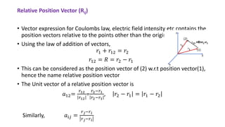
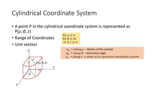
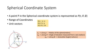
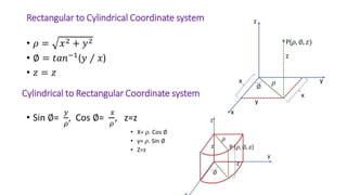
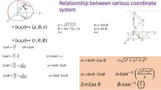
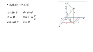
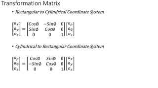
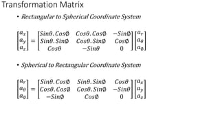
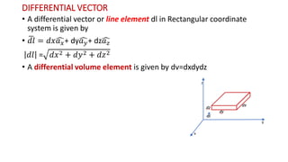
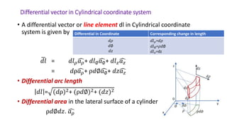
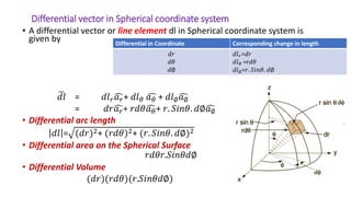
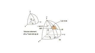
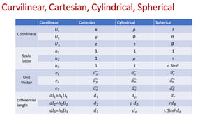
COORDINATE SYSTEM
Manju T. Kurian
AP, ECE
BM II CE
COORDINATE SYSTEM & TRANSFORMATION
• Coordinate systems are defined as a system used to represent a point
in space
• Classified a Orthogonal and Nonorthogonal Coordinate system
• For orthogonal coordinate system, the coordinates are mutually
perpendicular. The orthogonal coordinate systems include
• Rectangular or Cartesian coordinate system
• Cylindrical or circular coordinate system
• Spherical coordinate system
Rectangular Coordinate System
• This system is formed by three mutually orthogonal straight lines. The
three straight lines are called x,y,z axis. The point of intersection of
these lines are called the origin
• We will use the unit vectors ෞ
𝑎𝑥, ෞ
𝑎𝑦, ෞ
𝑎𝑧 to indicate the direction of
components along x,y,z axis respectively
• Range of coordinates x,y,z are −∞ < 𝑥 < ∞
−∞ < 𝑦 < ∞
−∞ < 𝑧 < ∞
• Vector Ԧ
𝐴 in cartesian coordinate can be written as
• Ԧ
𝐴=(Ax ,
Ay ,
A𝑧) =Ax ෞ
𝑎𝑥+ Ay ෞ
𝑎𝑦 + A𝑧ෞ
𝑎𝑧
• The position vector ത
𝒓 , a vector directed from the origin 0 to point P,
P(x,y,x) is given by
𝑂𝑃 = 𝑂𝐴 + 𝑂𝐵 + 𝑂𝐶
ҧ
𝑟 = 𝑥ෞ
𝑎𝑥 + 𝑦ෞ
𝑎𝑦 + 𝑧ෞ
𝑎𝑧
• x,y,z are scalar projections of ҧ
𝑟 𝑜𝑛 x,y and z axis
• Magnitude of ത
𝒓 is given by
ҧ
𝑟 = 𝑥2 + 𝑦2 + 𝑧2
• Orientation of ҧ
𝑟 on the x,y,z axis is given by 𝛼, 𝛽, 𝛾 𝑎𝑟𝑒 called Direction
Angles
ҧ
𝑟
𝑟
=
𝑥
𝑟
ෞ
𝑎𝑥 +
𝑦
𝑟
ෞ
𝑎𝑦 +
𝑧
𝑟
ෞ
𝑎𝑧
=Cos 𝛼 ෞ
𝑎𝑥+ Cos𝛽ෞ
𝑎𝑦+ Cos𝛾ෞ
𝑎𝑧
=𝑙𝑥 ෞ
𝑎𝑥+𝑙𝑦 ෞ
𝑎𝑦+ 𝑙𝑧ෞ
𝑎𝑧
𝑙𝑥, 𝑙𝑦, 𝑙𝑧 are known as Direction Cosines
• The unit vector along the direction of the position vector can be expressed in
terms of the direction cosines.
• Direction cosines are nothing but the magnitude of the position vector along the
coordinate axis
• Also Cos 𝛼 + Cos𝛽 + Cos𝛾 = 1
• Components in a specific direction
Consider a unit vector in a specific
direction.
The projection of Ԧ
𝐴 along the desired
direction is A.ො
𝑛 =A.Cos𝜃
This gives the magnitude of projection.
Scalar Component of Ԧ
𝐴 on 𝐵 = Ԧ
𝐴. ෞ
𝑎𝐵
Vector Component of Ԧ
𝐴 on 𝐵 =( Ԧ
𝐴. ෞ
𝑎𝐵) ෞ
𝑎𝐵
Relative Position Vector (Rij)
• Vector expression for Coulombs law, electric field intensity etc contains the
position vectors relative to the points other than the origin.
• Using the law of addition of vectors,
𝑟1 + 𝑟12 = 𝑟2
𝑟12 = 𝑅 = 𝑟2 − 𝑟1
• This can be considered as the position vector of (2) w.r.t position vector(1),
hence the name relative position vector
• The Unit vector of a relative position vector is
𝑎12=
𝑟12
𝑟12
=
𝑟2−𝑟1
𝑟2−𝑟1
, 𝑟2 − 𝑟1 = 𝑟1 − 𝑟2
Similarly, 𝑎𝑖𝑗 =
𝑟𝑗−𝑟𝑖
𝑟𝑗−𝑟𝑖
Cylindrical Coordinate System
• A point P in the cylindrical coordinate system is represented as
P(𝜌, ∅, 𝑧)
• Range of Coordinates
• Unit vectors
0≤ 𝜌 ≤ ∞
0≤ ∅ ≤ 2𝜋
-∞ ≤ 𝑧 ≤ ∞
𝑎𝜌 → 𝑎𝑙𝑜𝑛𝑔 𝜌 →Radius of the cylinder
𝑎∅ → 𝑎𝑙𝑜𝑛𝑔 ∅ →Azimuthal angle
𝑎𝑧 → 𝑎𝑙𝑜𝑛𝑔 𝑧 → 𝑠𝑎𝑚𝑒 𝑎𝑠 𝑖𝑛 𝑐𝑎𝑟𝑡𝑒𝑠𝑖𝑎𝑛 𝑐𝑜𝑜𝑟𝑑𝑖𝑛𝑎𝑡𝑒 𝑠𝑦𝑠𝑡𝑒𝑚
Spherical Coordinate System
• A point P in the Spherical coordinate system is represented as P(r, 𝜃, ∅)
• Range of Coordinates
• Unit vectors
0≤ 𝑟 ≤ ∞
0≤ 𝜃 ≤ 𝜋
0≤ ∅ ≤ 2𝜋
𝑎𝑟 → 𝑎𝑙𝑜𝑛𝑔 r →Radius of the sphere(meters)
𝑎𝜃 → 𝑎𝑙𝑜𝑛𝑔 𝜃 →Angle of elevation measured from z-axis (radians)
𝑎∅ → 𝑎𝑙𝑜𝑛𝑔 ∅ → Azimuthal Angle(𝑟𝑎𝑑𝑖𝑎𝑛𝑠)
Rectangular to Cylindrical Coordinate system
• 𝜌 = 𝑥2 + 𝑦2
• ∅ = 𝑡𝑎𝑛−1
(𝑦 ⁄ 𝑥)
• 𝑧 = 𝑧
• Sin ∅=
𝑦
𝜌
, Cos ∅=
𝑥
𝜌
, z=z
• X= 𝜌. Cos ∅
• y= 𝜌. Sin ∅
• Z=z
Cylindrical to Rectangular Coordinate system
Relationship between various coordinate
system
• (x,y,z)↔ 𝜌, ∅, 𝑧
• (x,y,z)↔ (𝑟, 𝜃, ∅)
𝜌 = 𝑥2 + 𝑦2 X= 𝜌. Cos ∅
∅ = 𝑡𝑎𝑛−1(𝑦 ⁄ 𝑥) y= 𝜌. Sin ∅
z=z z=z
𝑆𝑖𝑛𝜃 =
𝐶𝑃
𝑟
CP=r.Sin𝜃
Cos𝜃 =
𝑂𝐶
𝑟
=
𝑧
𝑟
z=r.Cos𝜃 = 𝑧
𝑆𝑖𝑛∅ =
𝐸𝐷
𝐶𝑃
=
𝑦
r.Sin𝜃
y= r.Sin𝜃. 𝑆𝑖𝑛∅
Cos∅ =
𝑂𝐸
𝐶𝑃
=
𝑥
r.Sin𝜃
x= r.Sin𝜃. Cos ∅
x= r.Sin𝜃. Cos ∅ r= 𝑥2 + 𝑦2 + 𝑧2
y= r.Sin𝜃. 𝑆𝑖𝑛∅ 𝜃=𝑡𝑎𝑛−1 𝑥2+𝑦2
𝑧
Z=r.Cos 𝜃 ∅=𝑡𝑎𝑛−1 𝑦
𝑥
• (𝜌, ∅, 𝑧)↔ 𝑟, 𝜃, ∅
𝜌=r.Sin 𝜃 r2= 𝜌2+z2
∅ = ∅ tan 𝜃 =
𝜌
𝑧
Z=r.Cos 𝜃 ∅ = ∅
Transformation Matrix
• Rectangular to Cylindrical Coordinate System
𝑎𝑥
𝑎𝑦
𝑎𝑧
=
𝐶𝑜𝑠∅ −𝑆𝑖𝑛∅ 0
𝑆𝑖𝑛∅ 𝐶𝑜𝑠∅ 0
0 0 1
𝑎𝜌
𝑎∅
𝑎𝑧
• Cylindrical to Rectangular Coordinate System
𝑎𝜌
𝑎∅
𝑎𝑧
=
𝐶𝑜𝑠∅ 𝑆𝑖𝑛∅ 0
−𝑆𝑖𝑛∅ 𝐶𝑜𝑠∅ 0
0 0 1
𝑎𝑥
𝑎𝑦
𝑎𝑧
Transformation Matrix
• Rectangular to Spherical Coordinate System
𝑎𝑥
𝑎𝑦
𝑎𝑧
=
𝑆𝑖𝑛𝜃. 𝐶𝑜𝑠∅ 𝐶𝑜𝑠𝜃. 𝐶𝑜𝑠∅ −𝑆𝑖𝑛∅
𝑆𝑖𝑛𝜃. 𝑆𝑖𝑛∅ 𝐶𝑜𝑠𝜃. 𝑆𝑖𝑛∅ 𝐶𝑜𝑠∅
𝐶𝑜𝑠𝜃 −𝑆𝑖𝑛𝜃 0
𝑎𝑟
𝑎𝜃
𝑎∅
• Spherical to Rectangular Coordinate System
𝑎𝑟
𝑎𝜃
𝑎∅
=
𝑆𝑖𝑛𝜃. 𝐶𝑜𝑠∅ 𝑆𝑖𝑛𝜃. 𝑆𝑖𝑛∅ 𝐶𝑜𝑠𝜃
𝐶𝑜𝑠𝜃. 𝐶𝑜𝑠∅ 𝐶𝑜𝑠𝜃. 𝑆𝑖𝑛∅ −𝑆𝑖𝑛𝜃
−𝑆𝑖𝑛∅ 𝐶𝑜𝑠∅ 0
𝑎𝑥
𝑎𝑦
𝑎𝑧
DIFFERENTIAL VECTOR
• A differential vector or line element dl in Rectangular coordinate
system is given by
• ഥ
𝑑𝑙 = 𝑑𝑥ෞ
𝑎𝑥+ dyෞ
𝑎𝑦+ dzෞ
𝑎𝑧
𝑑𝑙 = 𝑑𝑥2 + 𝑑𝑦2 + 𝑑𝑧2
• A differential volume element is given by dv=dxdydz
Differential vector in Cylindrical coordinate system
• A differential vector or line element dl in Cylindrical coordinate
system is given by
ഥ
𝑑𝑙 = 𝑑𝑙𝜌ෞ
𝑎𝜌+ 𝑑𝑙∅ෞ
𝑎∅+ 𝑑𝑙𝑧ෞ
𝑎𝑧
= 𝑑ρෞ
𝑎𝜌+ ρ𝑑∅ෞ
𝑎∅+ 𝑑𝑧ෞ
𝑎𝑧
• Differential arc length
𝑑𝑙 = (𝑑ρ)2+ (ρ𝑑∅)2+ (𝑑𝑧)2
• Differential area in the lateral surface of a cylinder
ρ𝑑∅𝑑𝑧. ෞ
𝑎𝜌
Differential in Coordinate Corresponding change in length
𝑑𝜌
𝑑∅
𝑑𝑧
𝑑𝑙𝜌=𝑑𝜌
𝑑𝑙∅=𝜌𝑑∅
𝑑𝑙𝑧=dz
Differential vector in Spherical coordinate system
• A differential vector or line element dl in Spherical coordinate system is
given by
ഥ
𝑑𝑙 = 𝑑𝑙𝑟ෞ
𝑎𝑟+ 𝑑𝑙𝜃 ෞ
𝑎𝜃 + 𝑑𝑙∅ෞ
𝑎∅
= 𝑑𝑟ෞ
𝑎𝑟+ 𝑟𝑑𝜃ෞ
𝑎𝜃+ 𝑟. 𝑆𝑖𝑛𝜃. 𝑑∅ෞ
𝑎∅
• Differential arc length
𝑑𝑙 = (𝑑𝑟)2+ (𝑟𝑑𝜃)2+ (𝑟. 𝑆𝑖𝑛𝜃. 𝑑∅)2
• Differential area on the Spherical Surface
𝑟𝑑𝜃𝑟.𝑆𝑖𝑛𝜃𝑑∅
• Differential Volume
(𝑑𝑟)(𝑟𝑑𝜃)(𝑟.𝑆𝑖𝑛𝜃𝑑∅)
Differential in Coordinate Corresponding change in length
𝑑𝑟
𝑑𝜃
𝑑∅
𝑑𝑙𝑟=𝑑𝑟
𝑑𝑙𝜃 =r𝑑𝜃
𝑑𝑙∅=𝑟. 𝑆𝑖𝑛𝜃. 𝑑∅
Curvilinear, Cartesian, Cylindrical, Spherical
Curvilinear Cartesian Cylindrical Spherical
Coordinate
𝑈1 x 𝜌 r
𝑈2 y ∅ 𝜃
𝑈3 z z ∅
Scale
factor
ℎ1 1 1 1
ℎ2 1 𝜌 r
ℎ3 1 1 r. Sin𝜃
Unit
Vector
𝑒1 ෞ
𝑎𝑥 ෞ
𝑎𝜌 ෞ
𝑎𝑟
𝑒2 ෞ
𝑎𝑦 ෞ
𝑎∅ ෞ
𝑎𝜃
𝑒3 ෞ
𝑎𝑧 ෞ
𝑎𝑧 ෞ
𝑎∅
Differential
length
𝑑𝑙1=ℎ1𝑈1 𝑑1 𝑑𝜌 𝑑𝑟
𝑑𝑙2=ℎ2𝑈2 𝑑2 𝜌 𝑑∅ r𝑑𝜃
𝑑𝑙3=ℎ3𝑈3 𝑑3 𝑑𝑧 r. Sin𝜃 𝑑∅

COORDINATE SYSTEM.pdf

  • 1.
    COORDINATE SYSTEM Manju T.Kurian AP, ECE BM II CE
  • 2.
    COORDINATE SYSTEM &TRANSFORMATION • Coordinate systems are defined as a system used to represent a point in space • Classified a Orthogonal and Nonorthogonal Coordinate system • For orthogonal coordinate system, the coordinates are mutually perpendicular. The orthogonal coordinate systems include • Rectangular or Cartesian coordinate system • Cylindrical or circular coordinate system • Spherical coordinate system
  • 3.
    Rectangular Coordinate System •This system is formed by three mutually orthogonal straight lines. The three straight lines are called x,y,z axis. The point of intersection of these lines are called the origin • We will use the unit vectors ෞ 𝑎𝑥, ෞ 𝑎𝑦, ෞ 𝑎𝑧 to indicate the direction of components along x,y,z axis respectively • Range of coordinates x,y,z are −∞ < 𝑥 < ∞ −∞ < 𝑦 < ∞ −∞ < 𝑧 < ∞ • Vector Ԧ 𝐴 in cartesian coordinate can be written as • Ԧ 𝐴=(Ax , Ay , A𝑧) =Ax ෞ 𝑎𝑥+ Ay ෞ 𝑎𝑦 + A𝑧ෞ 𝑎𝑧
  • 4.
    • The positionvector ത 𝒓 , a vector directed from the origin 0 to point P, P(x,y,x) is given by 𝑂𝑃 = 𝑂𝐴 + 𝑂𝐵 + 𝑂𝐶 ҧ 𝑟 = 𝑥ෞ 𝑎𝑥 + 𝑦ෞ 𝑎𝑦 + 𝑧ෞ 𝑎𝑧 • x,y,z are scalar projections of ҧ 𝑟 𝑜𝑛 x,y and z axis • Magnitude of ത 𝒓 is given by ҧ 𝑟 = 𝑥2 + 𝑦2 + 𝑧2 • Orientation of ҧ 𝑟 on the x,y,z axis is given by 𝛼, 𝛽, 𝛾 𝑎𝑟𝑒 called Direction Angles ҧ 𝑟 𝑟 = 𝑥 𝑟 ෞ 𝑎𝑥 + 𝑦 𝑟 ෞ 𝑎𝑦 + 𝑧 𝑟 ෞ 𝑎𝑧 =Cos 𝛼 ෞ 𝑎𝑥+ Cos𝛽ෞ 𝑎𝑦+ Cos𝛾ෞ 𝑎𝑧 =𝑙𝑥 ෞ 𝑎𝑥+𝑙𝑦 ෞ 𝑎𝑦+ 𝑙𝑧ෞ 𝑎𝑧 𝑙𝑥, 𝑙𝑦, 𝑙𝑧 are known as Direction Cosines
  • 5.
    • The unitvector along the direction of the position vector can be expressed in terms of the direction cosines. • Direction cosines are nothing but the magnitude of the position vector along the coordinate axis • Also Cos 𝛼 + Cos𝛽 + Cos𝛾 = 1 • Components in a specific direction Consider a unit vector in a specific direction. The projection of Ԧ 𝐴 along the desired direction is A.ො 𝑛 =A.Cos𝜃 This gives the magnitude of projection. Scalar Component of Ԧ 𝐴 on 𝐵 = Ԧ 𝐴. ෞ 𝑎𝐵 Vector Component of Ԧ 𝐴 on 𝐵 =( Ԧ 𝐴. ෞ 𝑎𝐵) ෞ 𝑎𝐵
  • 6.
    Relative Position Vector(Rij) • Vector expression for Coulombs law, electric field intensity etc contains the position vectors relative to the points other than the origin. • Using the law of addition of vectors, 𝑟1 + 𝑟12 = 𝑟2 𝑟12 = 𝑅 = 𝑟2 − 𝑟1 • This can be considered as the position vector of (2) w.r.t position vector(1), hence the name relative position vector • The Unit vector of a relative position vector is 𝑎12= 𝑟12 𝑟12 = 𝑟2−𝑟1 𝑟2−𝑟1 , 𝑟2 − 𝑟1 = 𝑟1 − 𝑟2 Similarly, 𝑎𝑖𝑗 = 𝑟𝑗−𝑟𝑖 𝑟𝑗−𝑟𝑖
  • 7.
    Cylindrical Coordinate System •A point P in the cylindrical coordinate system is represented as P(𝜌, ∅, 𝑧) • Range of Coordinates • Unit vectors 0≤ 𝜌 ≤ ∞ 0≤ ∅ ≤ 2𝜋 -∞ ≤ 𝑧 ≤ ∞ 𝑎𝜌 → 𝑎𝑙𝑜𝑛𝑔 𝜌 →Radius of the cylinder 𝑎∅ → 𝑎𝑙𝑜𝑛𝑔 ∅ →Azimuthal angle 𝑎𝑧 → 𝑎𝑙𝑜𝑛𝑔 𝑧 → 𝑠𝑎𝑚𝑒 𝑎𝑠 𝑖𝑛 𝑐𝑎𝑟𝑡𝑒𝑠𝑖𝑎𝑛 𝑐𝑜𝑜𝑟𝑑𝑖𝑛𝑎𝑡𝑒 𝑠𝑦𝑠𝑡𝑒𝑚
  • 8.
    Spherical Coordinate System •A point P in the Spherical coordinate system is represented as P(r, 𝜃, ∅) • Range of Coordinates • Unit vectors 0≤ 𝑟 ≤ ∞ 0≤ 𝜃 ≤ 𝜋 0≤ ∅ ≤ 2𝜋 𝑎𝑟 → 𝑎𝑙𝑜𝑛𝑔 r →Radius of the sphere(meters) 𝑎𝜃 → 𝑎𝑙𝑜𝑛𝑔 𝜃 →Angle of elevation measured from z-axis (radians) 𝑎∅ → 𝑎𝑙𝑜𝑛𝑔 ∅ → Azimuthal Angle(𝑟𝑎𝑑𝑖𝑎𝑛𝑠)
  • 9.
    Rectangular to CylindricalCoordinate system • 𝜌 = 𝑥2 + 𝑦2 • ∅ = 𝑡𝑎𝑛−1 (𝑦 ⁄ 𝑥) • 𝑧 = 𝑧 • Sin ∅= 𝑦 𝜌 , Cos ∅= 𝑥 𝜌 , z=z • X= 𝜌. Cos ∅ • y= 𝜌. Sin ∅ • Z=z Cylindrical to Rectangular Coordinate system
  • 10.
    Relationship between variouscoordinate system • (x,y,z)↔ 𝜌, ∅, 𝑧 • (x,y,z)↔ (𝑟, 𝜃, ∅) 𝜌 = 𝑥2 + 𝑦2 X= 𝜌. Cos ∅ ∅ = 𝑡𝑎𝑛−1(𝑦 ⁄ 𝑥) y= 𝜌. Sin ∅ z=z z=z 𝑆𝑖𝑛𝜃 = 𝐶𝑃 𝑟 CP=r.Sin𝜃 Cos𝜃 = 𝑂𝐶 𝑟 = 𝑧 𝑟 z=r.Cos𝜃 = 𝑧 𝑆𝑖𝑛∅ = 𝐸𝐷 𝐶𝑃 = 𝑦 r.Sin𝜃 y= r.Sin𝜃. 𝑆𝑖𝑛∅ Cos∅ = 𝑂𝐸 𝐶𝑃 = 𝑥 r.Sin𝜃 x= r.Sin𝜃. Cos ∅ x= r.Sin𝜃. Cos ∅ r= 𝑥2 + 𝑦2 + 𝑧2 y= r.Sin𝜃. 𝑆𝑖𝑛∅ 𝜃=𝑡𝑎𝑛−1 𝑥2+𝑦2 𝑧 Z=r.Cos 𝜃 ∅=𝑡𝑎𝑛−1 𝑦 𝑥
  • 11.
    • (𝜌, ∅,𝑧)↔ 𝑟, 𝜃, ∅ 𝜌=r.Sin 𝜃 r2= 𝜌2+z2 ∅ = ∅ tan 𝜃 = 𝜌 𝑧 Z=r.Cos 𝜃 ∅ = ∅
  • 12.
    Transformation Matrix • Rectangularto Cylindrical Coordinate System 𝑎𝑥 𝑎𝑦 𝑎𝑧 = 𝐶𝑜𝑠∅ −𝑆𝑖𝑛∅ 0 𝑆𝑖𝑛∅ 𝐶𝑜𝑠∅ 0 0 0 1 𝑎𝜌 𝑎∅ 𝑎𝑧 • Cylindrical to Rectangular Coordinate System 𝑎𝜌 𝑎∅ 𝑎𝑧 = 𝐶𝑜𝑠∅ 𝑆𝑖𝑛∅ 0 −𝑆𝑖𝑛∅ 𝐶𝑜𝑠∅ 0 0 0 1 𝑎𝑥 𝑎𝑦 𝑎𝑧
  • 13.
    Transformation Matrix • Rectangularto Spherical Coordinate System 𝑎𝑥 𝑎𝑦 𝑎𝑧 = 𝑆𝑖𝑛𝜃. 𝐶𝑜𝑠∅ 𝐶𝑜𝑠𝜃. 𝐶𝑜𝑠∅ −𝑆𝑖𝑛∅ 𝑆𝑖𝑛𝜃. 𝑆𝑖𝑛∅ 𝐶𝑜𝑠𝜃. 𝑆𝑖𝑛∅ 𝐶𝑜𝑠∅ 𝐶𝑜𝑠𝜃 −𝑆𝑖𝑛𝜃 0 𝑎𝑟 𝑎𝜃 𝑎∅ • Spherical to Rectangular Coordinate System 𝑎𝑟 𝑎𝜃 𝑎∅ = 𝑆𝑖𝑛𝜃. 𝐶𝑜𝑠∅ 𝑆𝑖𝑛𝜃. 𝑆𝑖𝑛∅ 𝐶𝑜𝑠𝜃 𝐶𝑜𝑠𝜃. 𝐶𝑜𝑠∅ 𝐶𝑜𝑠𝜃. 𝑆𝑖𝑛∅ −𝑆𝑖𝑛𝜃 −𝑆𝑖𝑛∅ 𝐶𝑜𝑠∅ 0 𝑎𝑥 𝑎𝑦 𝑎𝑧
  • 14.
    DIFFERENTIAL VECTOR • Adifferential vector or line element dl in Rectangular coordinate system is given by • ഥ 𝑑𝑙 = 𝑑𝑥ෞ 𝑎𝑥+ dyෞ 𝑎𝑦+ dzෞ 𝑎𝑧 𝑑𝑙 = 𝑑𝑥2 + 𝑑𝑦2 + 𝑑𝑧2 • A differential volume element is given by dv=dxdydz
  • 15.
    Differential vector inCylindrical coordinate system • A differential vector or line element dl in Cylindrical coordinate system is given by ഥ 𝑑𝑙 = 𝑑𝑙𝜌ෞ 𝑎𝜌+ 𝑑𝑙∅ෞ 𝑎∅+ 𝑑𝑙𝑧ෞ 𝑎𝑧 = 𝑑ρෞ 𝑎𝜌+ ρ𝑑∅ෞ 𝑎∅+ 𝑑𝑧ෞ 𝑎𝑧 • Differential arc length 𝑑𝑙 = (𝑑ρ)2+ (ρ𝑑∅)2+ (𝑑𝑧)2 • Differential area in the lateral surface of a cylinder ρ𝑑∅𝑑𝑧. ෞ 𝑎𝜌 Differential in Coordinate Corresponding change in length 𝑑𝜌 𝑑∅ 𝑑𝑧 𝑑𝑙𝜌=𝑑𝜌 𝑑𝑙∅=𝜌𝑑∅ 𝑑𝑙𝑧=dz
  • 16.
    Differential vector inSpherical coordinate system • A differential vector or line element dl in Spherical coordinate system is given by ഥ 𝑑𝑙 = 𝑑𝑙𝑟ෞ 𝑎𝑟+ 𝑑𝑙𝜃 ෞ 𝑎𝜃 + 𝑑𝑙∅ෞ 𝑎∅ = 𝑑𝑟ෞ 𝑎𝑟+ 𝑟𝑑𝜃ෞ 𝑎𝜃+ 𝑟. 𝑆𝑖𝑛𝜃. 𝑑∅ෞ 𝑎∅ • Differential arc length 𝑑𝑙 = (𝑑𝑟)2+ (𝑟𝑑𝜃)2+ (𝑟. 𝑆𝑖𝑛𝜃. 𝑑∅)2 • Differential area on the Spherical Surface 𝑟𝑑𝜃𝑟.𝑆𝑖𝑛𝜃𝑑∅ • Differential Volume (𝑑𝑟)(𝑟𝑑𝜃)(𝑟.𝑆𝑖𝑛𝜃𝑑∅) Differential in Coordinate Corresponding change in length 𝑑𝑟 𝑑𝜃 𝑑∅ 𝑑𝑙𝑟=𝑑𝑟 𝑑𝑙𝜃 =r𝑑𝜃 𝑑𝑙∅=𝑟. 𝑆𝑖𝑛𝜃. 𝑑∅
  • 18.
    Curvilinear, Cartesian, Cylindrical,Spherical Curvilinear Cartesian Cylindrical Spherical Coordinate 𝑈1 x 𝜌 r 𝑈2 y ∅ 𝜃 𝑈3 z z ∅ Scale factor ℎ1 1 1 1 ℎ2 1 𝜌 r ℎ3 1 1 r. Sin𝜃 Unit Vector 𝑒1 ෞ 𝑎𝑥 ෞ 𝑎𝜌 ෞ 𝑎𝑟 𝑒2 ෞ 𝑎𝑦 ෞ 𝑎∅ ෞ 𝑎𝜃 𝑒3 ෞ 𝑎𝑧 ෞ 𝑎𝑧 ෞ 𝑎∅ Differential length 𝑑𝑙1=ℎ1𝑈1 𝑑1 𝑑𝜌 𝑑𝑟 𝑑𝑙2=ℎ2𝑈2 𝑑2 𝜌 𝑑∅ r𝑑𝜃 𝑑𝑙3=ℎ3𝑈3 𝑑3 𝑑𝑧 r. Sin𝜃 𝑑∅