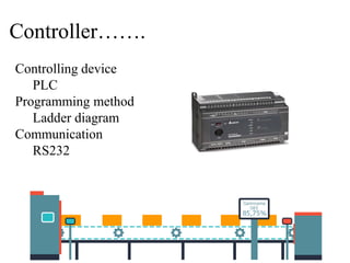
The document outlines the design and implementation of a ratio controller for a two conical tank interacting level system using PLC and SCADA, addressing challenges inherent to non-linear liquid level control in industrial applications. It describes the main project objectives, components used, control strategies, and difficulties faced during development, as well as the successful creation of a functioning system monitored through SCADA. Future prospects for research and potential applications in various instrumentation labs are also discussed.
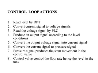
![Specifications
Make: watson smith
Input air: 20psi constant pressure
Signal input :( 4-20) ma
Output: pneumatic signal (3-15) psi
End connection: 1/2”BSP [F] thread
I to P converter](https://image.slidesharecdn.com/ratiocontrollerintwoconicaltankinteractinglevelsystem-180610104231/85/Ratio-controller-in-two-conical-tank-interacting-level-system-17-320.jpg)