Downloaded 654 times
![EFFICIENCY MOTOR
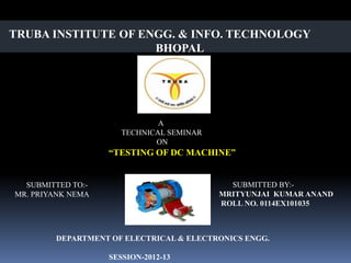
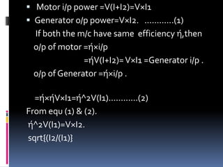
Motor o/p={ω(s1-s2)r× 9. 81}
Motor i/p= VtI.
ή(motor)={o/p}/{i/p}.
= [{ω(s1-s2)r× 9. 81}×100]/VtI
where; s1&s2 are the tension on the belt.
ω=2πn(motor speed in rad/sec
r=radius of pulley in meters(=1/2 out
side pulley dia+1/2 belt thickness)
Vt=terminal voltage & I=line current.](https://image.slidesharecdn.com/dcmc2-121009023055-phpapp01/85/testing-of-dc-machine-6-320.jpg)
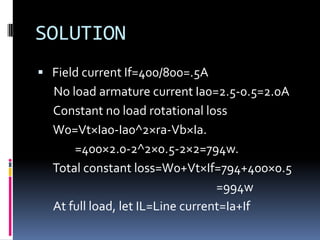
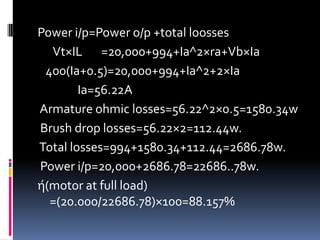
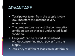
![SOLUTION
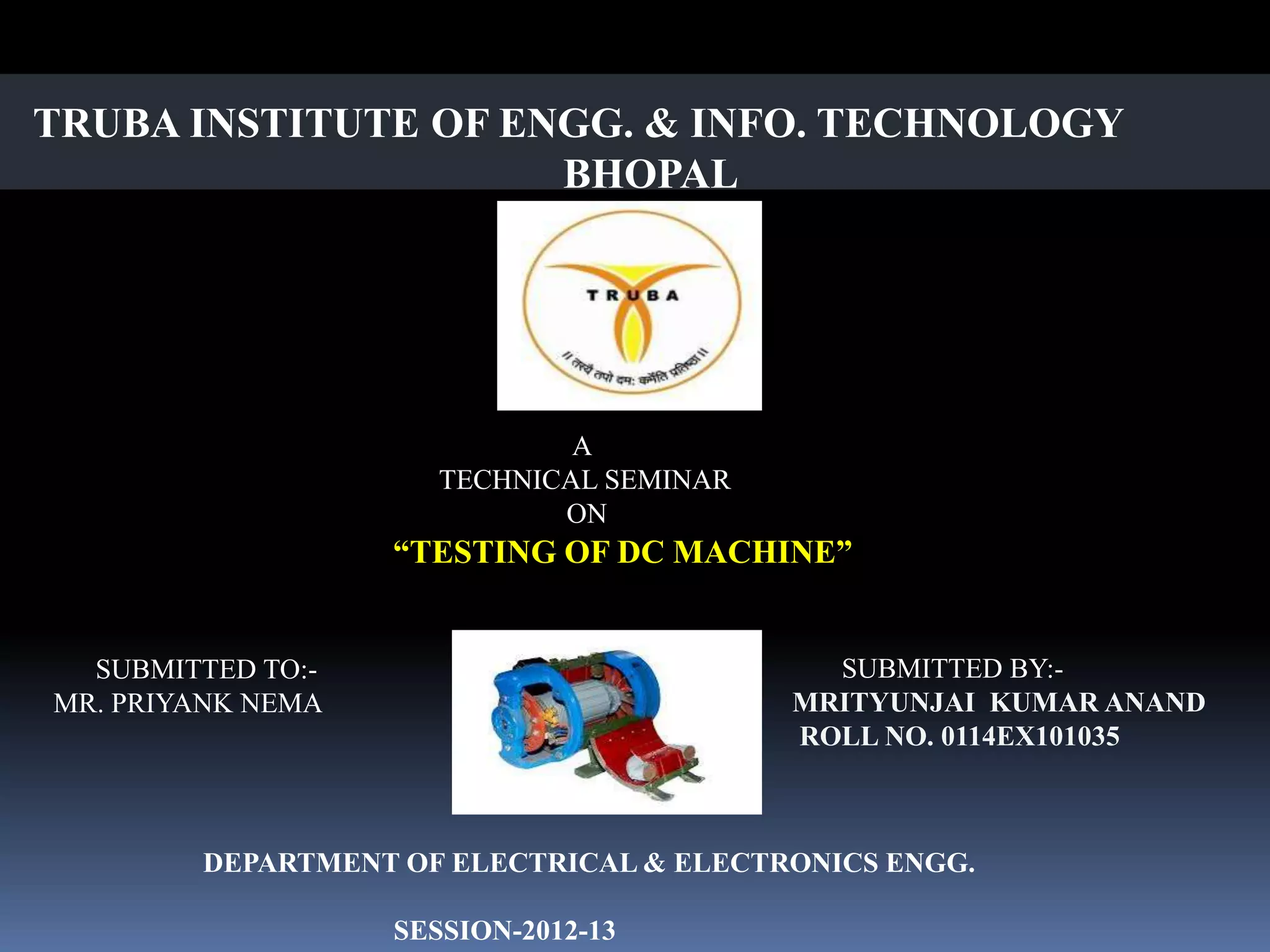
Shaft torque=(S1-S2)×Effective radius
=(25.9)[(19.5/2)+(0.5/2)]×(1/100)kg-m
=16×0.1×9.81 Nm=15.7 Nm
Shaft power=ω×Shaft torque
=[(2π×1500)/60]×15.7=2470w
Motor i/p=Vti=230×12.5=2875w
ή(motor efficiency at rated
load)=[2470/2875]×100=85.6%](https://image.slidesharecdn.com/dcmc2-121009023055-phpapp01/85/testing-of-dc-machine-8-320.jpg)
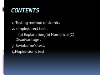
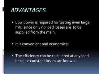
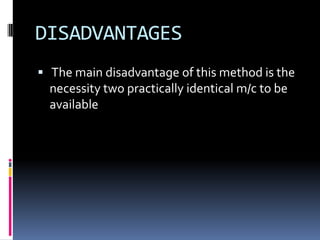
![ Let IL be the load current at which m/c
efficiency is required.
Generator efficiency
Generator o/p=Vt×IL
Armature current Ia=IL+If
Armature circuit loss= Ia^2×ra
ra=armature circuit resistance when hot.
Total loss=W0+ Ia^2×ra+Vt×If
ή(Generator)=[1-{(W0+
Ia^2×ra+Vt×If)}/{(Vt×IL+ W0+ Ia^2×ra+Vt×If)}]](https://image.slidesharecdn.com/dcmc2-121009023055-phpapp01/85/testing-of-dc-machine-13-320.jpg)
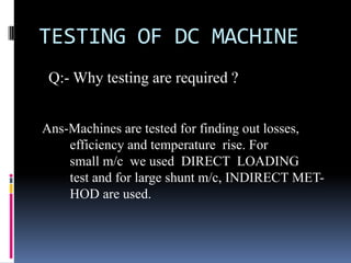
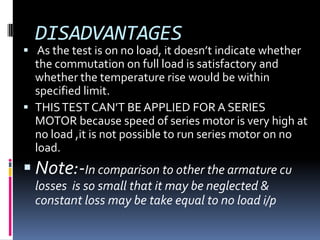
![ Motor efficiency
When m/c is working as a motor then
Ia=IL-If
Motor i/p=Vt×IL
ή(motor efficiency)=[1-
{(W0+Ia^2×ra+If×Vt)}/{(Vt×IL)}]](https://image.slidesharecdn.com/dcmc2-121009023055-phpapp01/85/testing-of-dc-machine-14-320.jpg)
![EFFICIENCY
Armature circuit loss in Generator =I2^2×ra .
Armature circuit loss in Motor=I1^2×ra .
Power drawn from supply= V×I.
No load rotational loss in two m/c=W0=
V×I-ra(I1^2+I2^2) .
No load rotational loss for each m/c=W0/2 .
Generator o/p= I2^2×ra.
Generator loss=Wg=(W0/2)+V×If2+ I2^2×ra.
ή(g)=[1-(Wg)/(V×I2+Wg)]](https://image.slidesharecdn.com/dcmc2-121009023055-phpapp01/85/testing-of-dc-machine-25-320.jpg)
![ Motor i/p=V(I1+If1)
Total motor losses Wm=(W0/2)+ V×If1
+I1^2×ra .
ή( Motor)=[1-(Wm)/V(I1+If2)]](https://image.slidesharecdn.com/dcmc2-121009023055-phpapp01/85/testing-of-dc-machine-26-320.jpg)


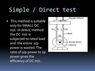
The document describes different testing methods for DC machines. It discusses the simple/direct test method, Swinburne's indirect test method, and Hopkinson's regenerative test method. The simple/direct test method calculates efficiency by directly loading the DC machine, but it is only suitable for small machines. Swinburne's method measures no-load losses to determine efficiency indirectly. Hopkinson's method couples two identical DC machines together to test them simultaneously, with one acting as a motor and the other as a generator.


![D.c. machine[1]](https://cdn.slidesharecdn.com/ss_thumbnails/d-160420172313-thumbnail.jpg?width=640&height=640&fit=bounds)


