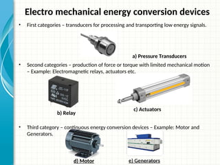
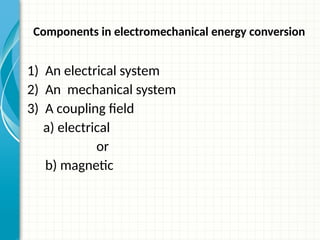
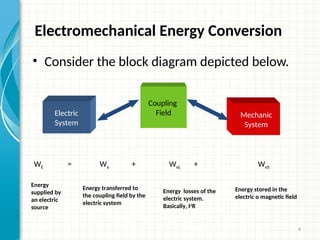
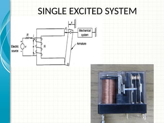
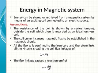
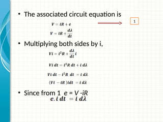
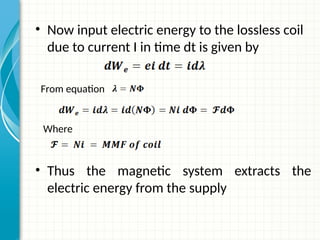
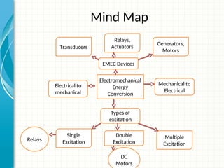
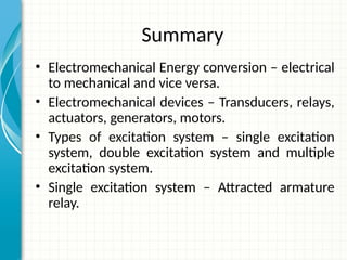
Basics – Electromechanical Energy Conversion
 The conversion of electrical energy into mechanical energy or
mechanical energy into electrical energy is called
Electromechanical energy conversion.
Electro mechanical energy conversion devices
• First categories – transducers for processing and transporting low energy signals.
• Second categories – production of force or torque with limited mechanical motion
– Example: Electromagnetic relays, actuators etc.
• Third category – continuous energy conversion devices – Example: Motor and
Generators.
e) Generators
d) Motor
b) Relay
a) Pressure Transducers
c) Actuators
Components in electromechanical energy conversion
1) An electrical system
2) An mechanical system
3) A coupling field
a) electrical
or
b) magnetic
Electromechanical Energy Conversion
• Consider the block diagram depicted below.
4
Electric
System
Coupling
Field Mechanic
System
WE = We + WeL + WeS
Energy
supplied by
an electric
source
Energy transferred to
the coupling field by the
electric system
Energy losses of the
electric system.
Basically, I2
R
Energy stored in the
electric o magnetic field
SINGLE EXCITED SYSTEM
Energy in Magnetic system
• Energy can be stored or retrieved from a magnetic system by
means of an exciting coil connected to an electric source.
Assumptions:
• The resistance of the coil is shown by a series lumping
outside the coil which then is regarded as an ideal loss-less
coil.
• The coil current causes magnetic flux to be established in the
magnetic circuit.
• All the flux ɸ is confined to the iron core and therefore links
all the N turns creating the coil flux linkages of
• The flux linkage causes a reaction emf of
• The associated circuit equation is
• Multiplying both sides by i,
• Since from 1 e = V -iR
1
• Now input electric energy to the lossless coil
due to current I in time dt is given by
• Thus the magnetic system extracts the
electric energy from the supply
From equation
Where
Magnetic Field Energy Stored
• Consider that the armature is held fixed at position x.
• As armature is not moving, the mechanical work done is zero.
• Hence according to energy balance equation, the entire energy
input gets stored in the magnetic field.
• The energy absorbed for a finite change in flux linkage can be
• Where is a function of
Mathematically it can be expressed as
When x increases the reluctance gets decreased, as a result increases
Concept of Co energy
• When armature is held open, entire mmf is
required to drive the flux through air gap.
• So,i-lamda relationship is linear
• The co energy can be expressed for linear case
as,
Comparison between Singly and Doubly
Excited Systems
Singly Excited System
• One coil takes active part in
energy conversion process.
• It has winding on stationary
part only.
• It works on induction or
asynchronous principle.
• Used in constant speed
application.
• Produce useful startup
torque.
• E.g. Magnetic relays, D.C.
generator, Induction
machine
Doubly Excited System
• Two coils take active part in
energy conversion process.
• It has winding on stationary
and rotating part.
• It works on synchronous
principle.
• Used in variable speed
application.
• Do not produce useful
startup torque.
• E.g. DC motor , Commutator
and Synchronous motor
Formative Assessment
1.Coenergy and field energy of a system is directly proportional to
A) F*Φ B) ½(F*Φ) C) S * Φ D) ½ (S * Φ)
2. The magnetization curve of an electromagnetic system with
airgap is
A) linear B) Non Linear C) Parabolic D) Hyperbolic
3. In linear Magnetic Circuit, the relationship between co energy
and field energy is,
A) coenergy ≠ field energy
B) coenergy > field energy
C) coenergy < field energy
D) coenergy = field energy
Discussion
Mind Map
Electromechanical
Energy
Conversion
EMEC Devices
Types of
excitation
Electrical to
mechanical
Mechanical to
Electrical
Transducers
Relays,
Actuators
Generators,
Motors
Single
Excitation
Double
Excitation
Multiple
Excitation
Relays
DC
Motors
Summary
• Electromechanical Energy conversion – electrical
to mechanical and vice versa.
• Electromechanical devices – Transducers, relays,
actuators, generators, motors.
• Types of excitation system – single excitation
system, double excitation system and multiple
excitation system.
• Single excitation system – Attracted armature
relay.
THANK YOU

Electromechanical energy Conversions.ppt

  • 1.
    Basics – ElectromechanicalEnergy Conversion  The conversion of electrical energy into mechanical energy or mechanical energy into electrical energy is called Electromechanical energy conversion.
  • 2.
    Electro mechanical energyconversion devices • First categories – transducers for processing and transporting low energy signals. • Second categories – production of force or torque with limited mechanical motion – Example: Electromagnetic relays, actuators etc. • Third category – continuous energy conversion devices – Example: Motor and Generators. e) Generators d) Motor b) Relay a) Pressure Transducers c) Actuators
  • 3.
    Components in electromechanicalenergy conversion 1) An electrical system 2) An mechanical system 3) A coupling field a) electrical or b) magnetic
  • 4.
    Electromechanical Energy Conversion •Consider the block diagram depicted below. 4 Electric System Coupling Field Mechanic System WE = We + WeL + WeS Energy supplied by an electric source Energy transferred to the coupling field by the electric system Energy losses of the electric system. Basically, I2 R Energy stored in the electric o magnetic field
  • 5.
  • 6.
    Energy in Magneticsystem • Energy can be stored or retrieved from a magnetic system by means of an exciting coil connected to an electric source. Assumptions: • The resistance of the coil is shown by a series lumping outside the coil which then is regarded as an ideal loss-less coil. • The coil current causes magnetic flux to be established in the magnetic circuit. • All the flux ɸ is confined to the iron core and therefore links all the N turns creating the coil flux linkages of • The flux linkage causes a reaction emf of
  • 7.
    • The associatedcircuit equation is • Multiplying both sides by i, • Since from 1 e = V -iR 1
  • 8.
    • Now inputelectric energy to the lossless coil due to current I in time dt is given by • Thus the magnetic system extracts the electric energy from the supply From equation Where
  • 9.
    Magnetic Field EnergyStored • Consider that the armature is held fixed at position x. • As armature is not moving, the mechanical work done is zero. • Hence according to energy balance equation, the entire energy input gets stored in the magnetic field. • The energy absorbed for a finite change in flux linkage can be • Where is a function of
  • 10.
    Mathematically it canbe expressed as When x increases the reluctance gets decreased, as a result increases
  • 11.
    Concept of Coenergy • When armature is held open, entire mmf is required to drive the flux through air gap. • So,i-lamda relationship is linear
  • 13.
    • The coenergy can be expressed for linear case as,
  • 14.
    Comparison between Singlyand Doubly Excited Systems Singly Excited System • One coil takes active part in energy conversion process. • It has winding on stationary part only. • It works on induction or asynchronous principle. • Used in constant speed application. • Produce useful startup torque. • E.g. Magnetic relays, D.C. generator, Induction machine Doubly Excited System • Two coils take active part in energy conversion process. • It has winding on stationary and rotating part. • It works on synchronous principle. • Used in variable speed application. • Do not produce useful startup torque. • E.g. DC motor , Commutator and Synchronous motor
  • 15.
    Formative Assessment 1.Coenergy andfield energy of a system is directly proportional to A) F*Φ B) ½(F*Φ) C) S * Φ D) ½ (S * Φ) 2. The magnetization curve of an electromagnetic system with airgap is A) linear B) Non Linear C) Parabolic D) Hyperbolic 3. In linear Magnetic Circuit, the relationship between co energy and field energy is, A) coenergy ≠ field energy B) coenergy > field energy C) coenergy < field energy D) coenergy = field energy
  • 16.
  • 17.
    Mind Map Electromechanical Energy Conversion EMEC Devices Typesof excitation Electrical to mechanical Mechanical to Electrical Transducers Relays, Actuators Generators, Motors Single Excitation Double Excitation Multiple Excitation Relays DC Motors
  • 18.
    Summary • Electromechanical Energyconversion – electrical to mechanical and vice versa. • Electromechanical devices – Transducers, relays, actuators, generators, motors. • Types of excitation system – single excitation system, double excitation system and multiple excitation system. • Single excitation system – Attracted armature relay.
  • 19.