Download to read offline
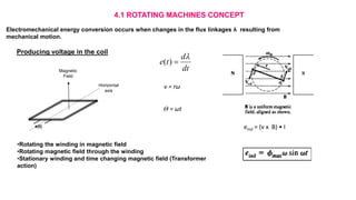
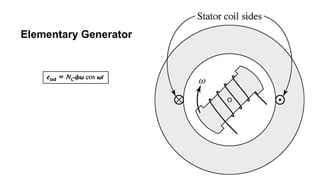
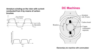
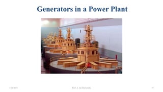
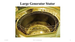
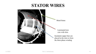
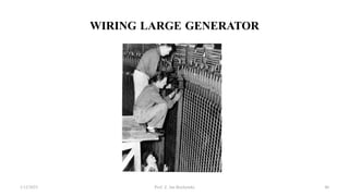
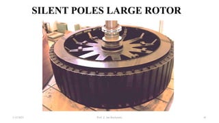
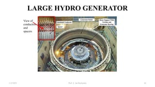
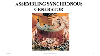
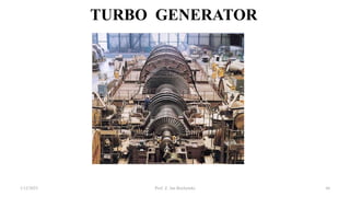
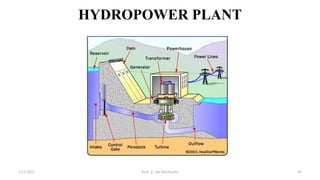
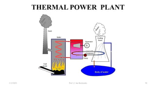
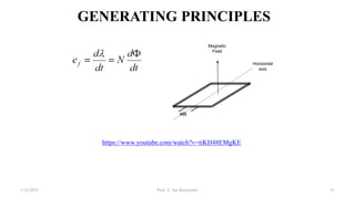
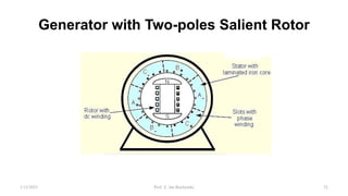
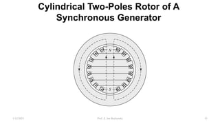
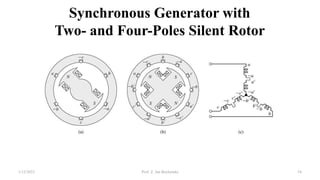
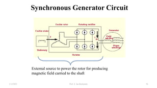


This document provides information about synchronous generators and AC machines. It discusses the basic concepts of rotating machines and electromechanical energy conversion. It describes how synchronous and induction machines work, including their rotor and stator configurations. The document also covers DC machines and their use of commutators. In addition, it discusses synchronous generator components like stators, rotors, poles and windings. It provides examples of large hydro and thermal power plant generators. Overall, the document provides a comprehensive overview of synchronous generator principles and components.


