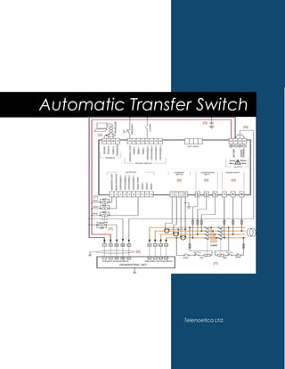
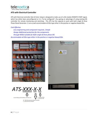
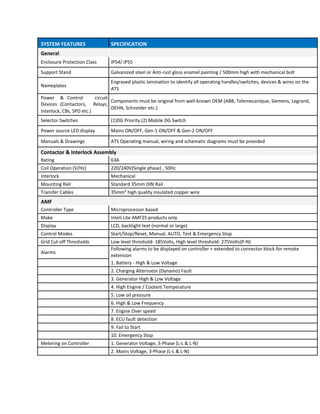
Automatic Transfer Switch
Telenoetica Ltd.
Table of Contents
Transfer Switch...............................................................................................................................................................2
Category of ATS Panel..................................................................................................................................................3
ATS with Microprocessor based Controller......................................................................................................3
Introduction..........................................................................................................................................................................3
Wiring Diagram..............................................................................................................................................................4
ATS with Electrical Controller....................................................................................................................................6
Introduction..........................................................................................................................................................................6
Wiring Diagram..............................................................................................................................................................7
1 | P a g e
Transfer Switch
A transfer switch is an electrical switch that reconnects electric power source from its primary source to a
standby source. Switches may be manually or automatically operated. An Automatic Changeover/Transfer
Switch (ATS) is used with standby systems (Backup Generators), so that the generator may provide temporary
electrical power if the utility source fails.
In the telecommunications industry, providing a high level of service and dependability is crucial. Lost
power means an interruption in service for your customers and lost business for your company. For instance,
with cell sites scattered across a wide geographical region and in many remote areas, the chances of an
interruption in power are increased, making Automatic Transfer Switches a valuable resource at each location.
Generator transfer systems can be manual, automatic, or a combination of both
An ATS not only safely switches‐in the backup generator as a temporary source of electric power; it also
commands the backup generator to start, based on certain conditions it continuously monitors on the primary
feed. The transfer switch isolates the backup generator from the electric utility, when the generator is on and is
providing temporary power. The control capability of a transfer switch may be manual only, or a combination of
automatic and manual.
For example, on a standard Telecom site equipped with a backup generator and an ATS, when an electric
utility (NEPA) outage occurs, the ATS will tell the backup generator to start. Once the ATS sees that the generator
is ready to provide electric power, the ATS breaks the site's connection to the electric utility and connects the
generator to the site's main electrical panel. The generator supply power to the site electric load, but is not
connected to the electric utility. Isolation of the generator from the distribution system is required to protect the
generator from overload, and to prevent accidental energization of the service wiring.
When mains is restored, it commutates your panel wiring from the generator back to the utility. When the
generator is disconnected, it goes into a cool‐down process and then automatically shuts down.
2 | P a g e
The design of the ATS transfer switch is based on proven load break switch technology, which
guarantees both the continuity of the power supply and the safety of operators. Its stable positions
allow energy consumption to be minimised whilst ensuring maximum immunity to electrical network
disturbances, making this a truly robust and reliable solution.
Locally stocked and technically supported within, Telenoetica have both off the shelf and customised
ATS solutions to meet most technical and cost requirements.
Category of ATS Panel
1) ATS with Microprocessor based Controller
2) ATS with Electrical Controller (Using DG Controller for Remote operations)
ATS with Microprocessor based Controller
To maintain dependable service, each cell site must be monitored 24 hours a day. This can be very difficult
without some type of remote monitoring and testing capability. Our Automatic Transfer Switch, combined with
AMF monitoring and control management system, is a cost effective, packaged solution which can help meet
both of these challenging objectives without a major investment at each cell site. With AMF connectivity
solutions you can remotely monitor and control numerous sites from around the corner or around the world.
Safe & Reliable Operation
The changeover mechanism has 3 stable
positions, which ensure isolation of the two
asynchronous power supplies
Unwanted Operation prevention
ATS has a selection to choose between manual
and Automatic Operation using selector
switch/Handle
Bypass Functionality
In case of both Mains and DG failure ATS can
be bypassed to use a mobile Generator
Support of wireless Internet
Optional internet with Control and monitoring
over webpages
Less Engineering and programming
Remote monitoring helps reduce call out cost
of Service Engineers
Suitable for Both single & three phase DG
Available with Single or Dual AMF, with 25‐1000 amps rating
1 2 3 4
A
L1 GEN
31
LOAD PH
L1
91
F10
B
TS
32
NEPA AUX
9033
C
GEN
30
N GEN
D
Title ATS DOUBLE PANEL TELENOETICA LIMITED
COUPLER DIAGRAM
VICTORIA ISLAND
LAGOS
Size Number Revision
A4
3 A00
Date: 06-07-2015 Sheet of 3
File: H:ATS PanalPage 3.SchDoc Drawn By: ER.DEEPAK JAISWAL
A
B
C
D
1 2 3 4
Page 5
ATS with Electrical Controller
ATS with Electrical controller (Set of timer relays) is designed to make use of a DG module REMOTE START signal,
which has either been preconfigured or it is “to be configured”, thus giving an advantage of using existing DG
controller for remote monitoring and start/stop . This ATS has the capacity to work with both single & three
Phase Diesel Generator. It can as well accommodate all DGs type either in the positive or negative biased DGs.
Cost Effective
Less engineering and component required , Simple
Design Additional protection for the components
through MCBs Suitable for Both single & three phase DG
Accommodate all DGs type either in the positive or negative biased DGs
6 | P a g e
SYSTEM FEATURES SPECIFICATION
General
Enclosure Protection Class IP54/ IP55
Support Stand Galvanized steel or Anti‐rust gloss enamel painting / 500mm high with mechanical bolt
Nameplates
Engraved plastic lamination to identify all operating handles/switches, devices & wires on the
ATS
Power & Control circuit
Components must be original from well‐known OEM (ABB, Telemecanique, Siemens, Legrand,
Devices (Contactors, Relays,
DEHN, Schneider etc.)
Interlock, CBs, SPD etc.)
Selector Switches (1)DG Priority (2) Mobile DG Switch
Power source LED display Mains ON/OFF, Gen‐1 ON/OFF & Gen‐2 ON/OFF
Manuals & Drawings ATS Operating manual, wiring and schematic diagrams must be provided
Contactor & Interlock Assembly
Rating 63A
Coil Operation (V/Hz) 220/240V(Single phase) , 50Hz
Interlock Mechanical
Mounting Rail Standard 35mm DIN Rail
Transfer Cables 35mm² high quality insulated copper wire
AMF
Controller Type Microprocessor based
Make Inteli Lite AMF25 products only
Display LCD, backlight text (normal or large)
Control Modes Start/Stop/Reset, Manual, AUTO, Test & Emergency Stop
Grid Cut‐off Thresholds Low level threshold‐ 185Volts, High level threshold‐ 275Volts(P‐N)
Alarms
Following alarms to be displayed on controller + extended to connector block for remote
extension
1. Battery ‐ High & Low Voltage
2. Charging Alternator (Dynamo) Fault
3. Generator High & Low Voltage
4. High Engine / Coolant Temperature
5. Low oil pressure
6. High & Low Frequency
7. Engine Over speed
8. ECU fault detection
9. Fail to Start
10. Emergency Stop
Metering on Controller 1. Generator Voltage, 3‐Phase (L‐L & L‐N)
2. Mains Voltage, 3‐Phase (L‐L & L‐N)
Ats brochure

Ats brochure

  • 1.
  • 2.
    Table of Contents TransferSwitch...............................................................................................................................................................2 Category of ATS Panel..................................................................................................................................................3 ATS with Microprocessor based Controller......................................................................................................3 Introduction..........................................................................................................................................................................3 Wiring Diagram..............................................................................................................................................................4 ATS with Electrical Controller....................................................................................................................................6 Introduction..........................................................................................................................................................................6 Wiring Diagram..............................................................................................................................................................7 1 | P a g e
  • 3.
    Transfer Switch A transferswitch is an electrical switch that reconnects electric power source from its primary source to a standby source. Switches may be manually or automatically operated. An Automatic Changeover/Transfer Switch (ATS) is used with standby systems (Backup Generators), so that the generator may provide temporary electrical power if the utility source fails. In the telecommunications industry, providing a high level of service and dependability is crucial. Lost power means an interruption in service for your customers and lost business for your company. For instance, with cell sites scattered across a wide geographical region and in many remote areas, the chances of an interruption in power are increased, making Automatic Transfer Switches a valuable resource at each location. Generator transfer systems can be manual, automatic, or a combination of both An ATS not only safely switches‐in the backup generator as a temporary source of electric power; it also commands the backup generator to start, based on certain conditions it continuously monitors on the primary feed. The transfer switch isolates the backup generator from the electric utility, when the generator is on and is providing temporary power. The control capability of a transfer switch may be manual only, or a combination of automatic and manual. For example, on a standard Telecom site equipped with a backup generator and an ATS, when an electric utility (NEPA) outage occurs, the ATS will tell the backup generator to start. Once the ATS sees that the generator is ready to provide electric power, the ATS breaks the site's connection to the electric utility and connects the generator to the site's main electrical panel. The generator supply power to the site electric load, but is not connected to the electric utility. Isolation of the generator from the distribution system is required to protect the generator from overload, and to prevent accidental energization of the service wiring. When mains is restored, it commutates your panel wiring from the generator back to the utility. When the generator is disconnected, it goes into a cool‐down process and then automatically shuts down. 2 | P a g e
  • 4.
    The design ofthe ATS transfer switch is based on proven load break switch technology, which guarantees both the continuity of the power supply and the safety of operators. Its stable positions allow energy consumption to be minimised whilst ensuring maximum immunity to electrical network disturbances, making this a truly robust and reliable solution. Locally stocked and technically supported within, Telenoetica have both off the shelf and customised ATS solutions to meet most technical and cost requirements. Category of ATS Panel 1) ATS with Microprocessor based Controller 2) ATS with Electrical Controller (Using DG Controller for Remote operations) ATS with Microprocessor based Controller To maintain dependable service, each cell site must be monitored 24 hours a day. This can be very difficult without some type of remote monitoring and testing capability. Our Automatic Transfer Switch, combined with AMF monitoring and control management system, is a cost effective, packaged solution which can help meet both of these challenging objectives without a major investment at each cell site. With AMF connectivity solutions you can remotely monitor and control numerous sites from around the corner or around the world. Safe & Reliable Operation The changeover mechanism has 3 stable positions, which ensure isolation of the two asynchronous power supplies Unwanted Operation prevention ATS has a selection to choose between manual and Automatic Operation using selector switch/Handle Bypass Functionality In case of both Mains and DG failure ATS can be bypassed to use a mobile Generator Support of wireless Internet Optional internet with Control and monitoring over webpages Less Engineering and programming Remote monitoring helps reduce call out cost of Service Engineers Suitable for Both single & three phase DG Available with Single or Dual AMF, with 25‐1000 amps rating
  • 6.
    1 2 34 A L1 GEN 31 LOAD PH L1 91 F10 B TS 32 NEPA AUX 9033 C GEN 30 N GEN D Title ATS DOUBLE PANEL TELENOETICA LIMITED COUPLER DIAGRAM VICTORIA ISLAND LAGOS Size Number Revision A4 3 A00 Date: 06-07-2015 Sheet of 3 File: H:ATS PanalPage 3.SchDoc Drawn By: ER.DEEPAK JAISWAL A B C D 1 2 3 4 Page 5
  • 7.
    ATS with ElectricalController ATS with Electrical controller (Set of timer relays) is designed to make use of a DG module REMOTE START signal, which has either been preconfigured or it is “to be configured”, thus giving an advantage of using existing DG controller for remote monitoring and start/stop . This ATS has the capacity to work with both single & three Phase Diesel Generator. It can as well accommodate all DGs type either in the positive or negative biased DGs. Cost Effective Less engineering and component required , Simple Design Additional protection for the components through MCBs Suitable for Both single & three phase DG Accommodate all DGs type either in the positive or negative biased DGs 6 | P a g e
  • 9.
    SYSTEM FEATURES SPECIFICATION General EnclosureProtection Class IP54/ IP55 Support Stand Galvanized steel or Anti‐rust gloss enamel painting / 500mm high with mechanical bolt Nameplates Engraved plastic lamination to identify all operating handles/switches, devices & wires on the ATS Power & Control circuit Components must be original from well‐known OEM (ABB, Telemecanique, Siemens, Legrand, Devices (Contactors, Relays, DEHN, Schneider etc.) Interlock, CBs, SPD etc.) Selector Switches (1)DG Priority (2) Mobile DG Switch Power source LED display Mains ON/OFF, Gen‐1 ON/OFF & Gen‐2 ON/OFF Manuals & Drawings ATS Operating manual, wiring and schematic diagrams must be provided Contactor & Interlock Assembly Rating 63A Coil Operation (V/Hz) 220/240V(Single phase) , 50Hz Interlock Mechanical Mounting Rail Standard 35mm DIN Rail Transfer Cables 35mm² high quality insulated copper wire AMF Controller Type Microprocessor based Make Inteli Lite AMF25 products only Display LCD, backlight text (normal or large) Control Modes Start/Stop/Reset, Manual, AUTO, Test & Emergency Stop Grid Cut‐off Thresholds Low level threshold‐ 185Volts, High level threshold‐ 275Volts(P‐N) Alarms Following alarms to be displayed on controller + extended to connector block for remote extension 1. Battery ‐ High & Low Voltage 2. Charging Alternator (Dynamo) Fault 3. Generator High & Low Voltage 4. High Engine / Coolant Temperature 5. Low oil pressure 6. High & Low Frequency 7. Engine Over speed 8. ECU fault detection 9. Fail to Start 10. Emergency Stop Metering on Controller 1. Generator Voltage, 3‐Phase (L‐L & L‐N) 2. Mains Voltage, 3‐Phase (L‐L & L‐N)