Download to read offline
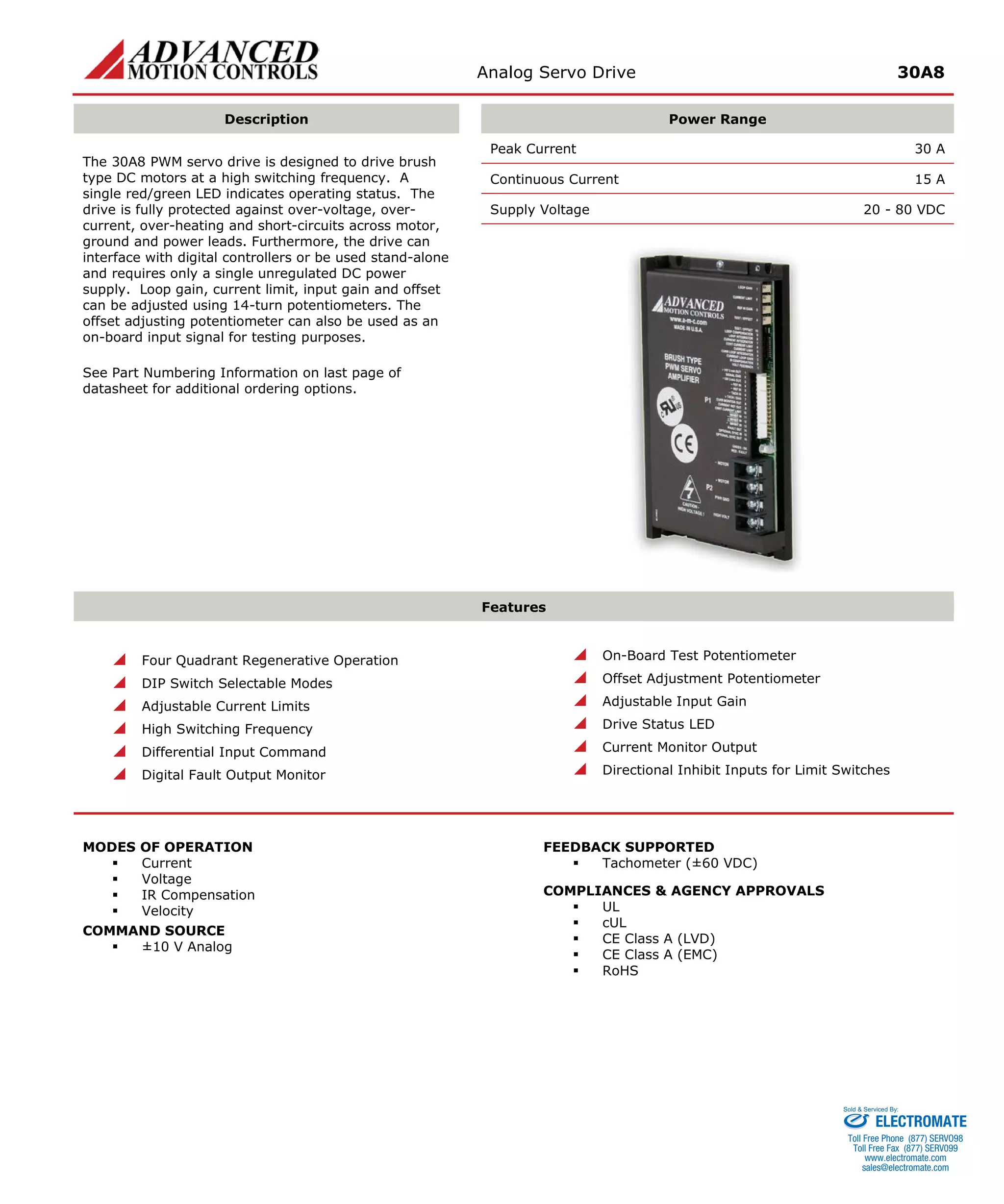
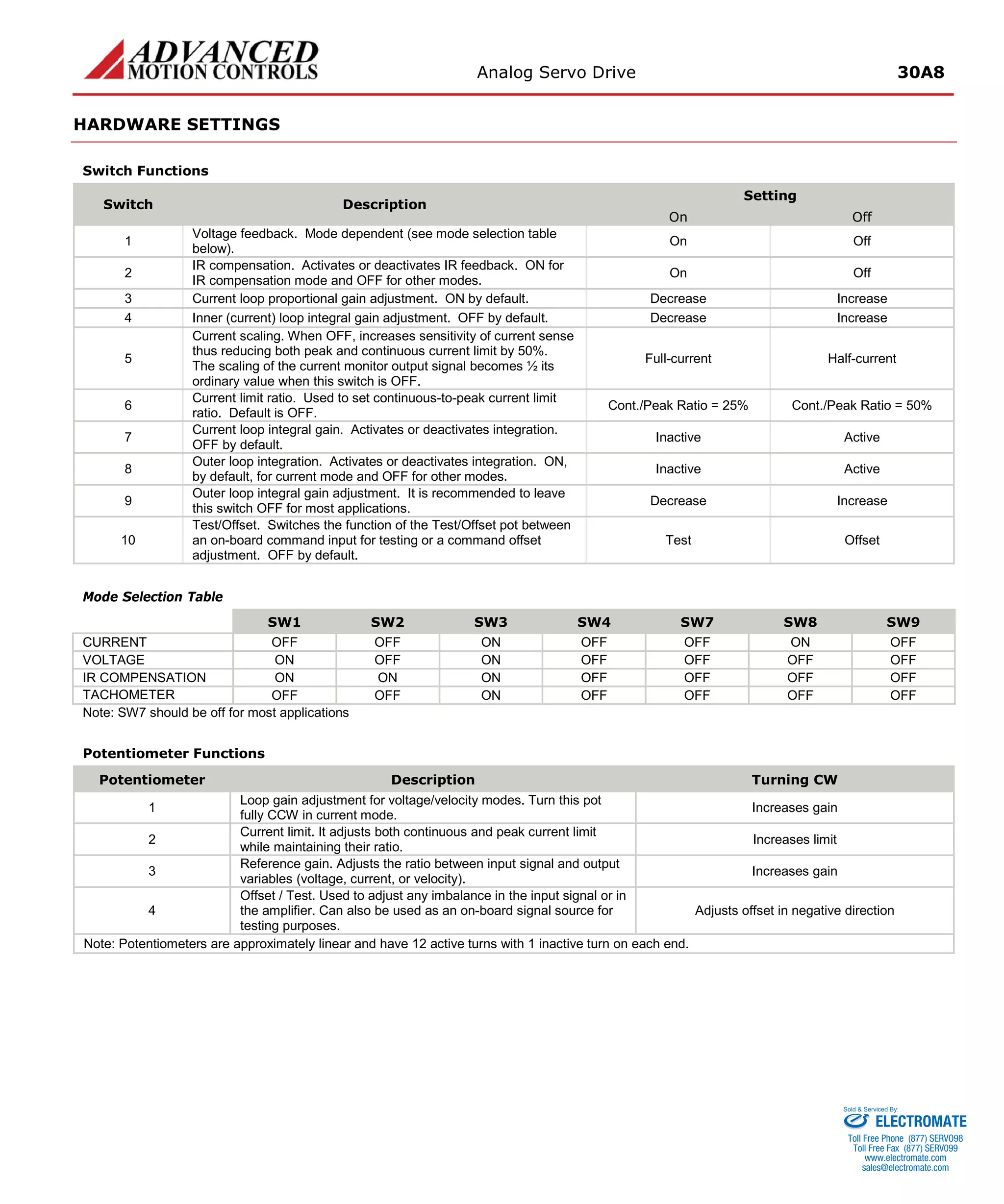

The document describes an analog servo drive that can provide up to 30A of peak current and 15A of continuous current. It is designed to drive brush DC motors and interface with digital controllers. It has adjustable current limits and loop gains, four quadrants of regenerative operation, and fault protection. Modes of operation include current, voltage, IR compensation and velocity control.


![Vibe Coding vs. Spec-Driven Development [Free Meetup]](https://cdn.slidesharecdn.com/ss_thumbnails/vibecodingvsspecdrivendevelopment-251209105622-43f455e7-thumbnail.jpg?width=640&height=640&fit=bounds)


