Download to read offline

![5
Uout
23.9
Vdc
Iout
9.76
Adc
Err
!!!
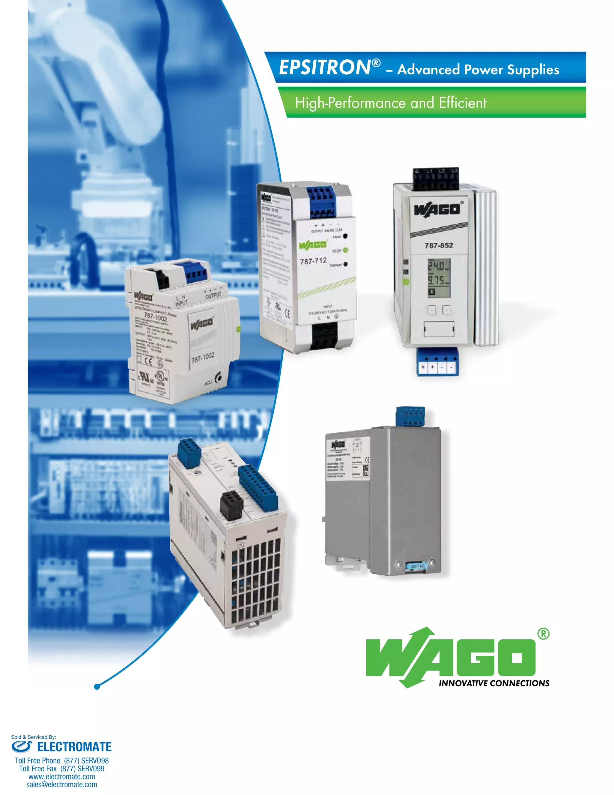
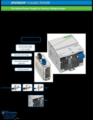
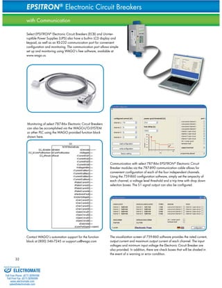
High-Performance
The PRO Power Supplies provide extra power via TopBoost and PowerBoost. In
addition, the overload behavior of devices equipped with line monitor* can be
adjusted, allowing them to be adapted to the relevant application.
SET s
I.Co
Uout
Uout
SET s
I.Co
t [sec] ü
Uout [V] ü
Iout [%] ü
200
100
24
Uout [V] ü
Iout [%] ü
200
100
24
SET
Iout
I.Co
Uout [V] ü
200
SET
Iout
I.Co
0
0
0 5 10 15 0 5 10 15
t [sec] ü
005
Iout
I.t
Iout
000
Iout
I.t
s
Top boost
Inom +60 A
Power
boost Constant current
Overcurrent phase
Top boost
Inom +60 A
Power
boost
Constant
current Fuse mode
Overcurrent phase
t [sec] ü
15 t [sec] ü
Iout [%] ü
100
24
0
0 5 10 15
005
Iout
I.t
Iout
000
Iout
I.t
s
current
phase
Top boost
Inom +60 A
Power
boost
Constant
current Fuse mode
Overcurrent phase
Overload behavior
The constant current operation available in all PRO Power Supplies, where the
output current is limited to 1.1 times the rated current in case of overload, can be
limited temporally via fuse mode in devices equipped with line monitor. In fuse mode
operation, the output current is switched off cyclically on overload or short circuit,
which safely prevents over-heating due to the sharply-reduced power flow.
1 2 3 4 5 6 7 8
RxPC TxPC
787-890
Innovative Communication
1. LEDs: When the device is running without any errors, the green LED illuminates. Non-critical
errors are signaled by the (optional*) yellow LED, while critical errors are indicated
by the red LED.
2. Display (optional*): The 787-85x units with Line Monitor continuously provide the
current and voltage output and also offer comprehensive line monitoring. In the event of
an error, a diagnostic can be preformed via an integrated fault memory. Function keys for
parameter setting are located on the front of the device.
3. Active signal outputs (optional*): Four active signal outputs for function monitoring
are located on the front of the device. The corresponding states can be transferred to the
higher-level control system. These outputs do not require separate signal/supply voltage, as
they are being supplied by the output of this device. Two of the four signal outputs can be
user-defined using the free 759-850 Configuration Software, and may be set up to represent
more than one fault condition per output (e.g. for the purpose of generating a group signal
for all critical states).
4. Interface (optional*): The device can communicate with a PC or higher-level control
system via the serial interface. The 759-851 Software is used to visualize all relevant data
on a PC; configuring the device is performed via 759-850 Software. Both software versions
can be downloaded free of charge from www.wago.us. The 787-890 Serial Communication
Cable is available as an accessory for connection to the RS-232 interface. For more detail
on this feature, see pages 30 and 31 of this brochure.
PowerBoost
Conventional switch mode power supplies typically set current limiting at 1.1 times the rated
output current. The use of these power supplies becomes very problematic as soon as heavy
starting loads are switched in, since these power supplies are not able to provide sufficient
current for them. The PRO Series has power reserves which can provide twice the current at
constant voltage for at least 4 seconds. This ensures reliable operation and removes the need
for expensive oversizing of switch mode power supplies.
TopBoost
In order for high-speed magnetic miniature circuit breakers to trip, high currents (that are
significantly higher than the rated current) are required for a period of 10 to 12 milliseconds.
The PRO Series of power supplies are able to supply a powerful 60 A above the rated
current for 50 milliseconds. This enables a faulty branch to be shut down selectively in the
event of a short circuit while, the remaining loads continue unaffected.
Sold & Serviced By:
ELECTROMATE
Toll Free Phone (877) SERVO98
Toll Free Fax (877) SERV099
www.electromate.com
sales@electromate.com](https://image.slidesharecdn.com/wagoepsitronpowersuppliescatalog-141018125429-conversion-gate01/85/Wago-epsitron-power_supplies_catalog-5-320.jpg)
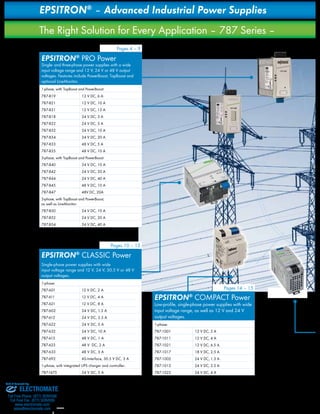
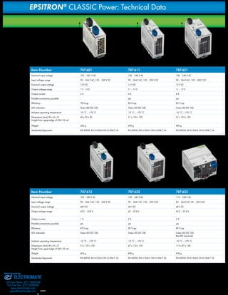
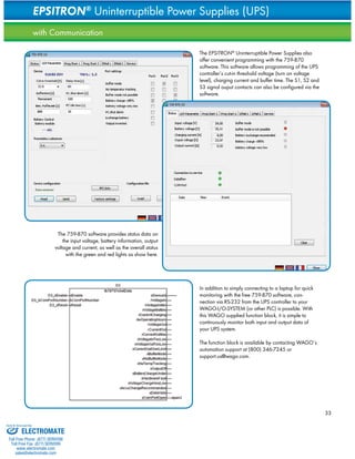
![Compact and Easy to Mount
The CLASSIC Power Supplies have a compact and very robust metal housing. Mounting
on DIN 35 rails is quick and reliable thanks to the easily-accessible plate on the device.
Universal Supply
High Load-Carrying Capacity
Quick Status
All CLASSIC Power Supplies have an operating indicator that signals the availability of the
output voltage via a green LED. Devices with output power > 150W also have an overcurrent
indicator, indicated by a red LED. This makes start-up easier and gives maintenance personnel
faster information about the state of the machine or system.
11
Iout [%] Ñ
100
24
Constant current
0
0 5 10 15 t [sec] Ñ
Uout [V] Ñ
Overcurrent phase
The wide range of input voltages of the CLASSIC Power Supplies allows the feed with AC 90
to 264 V. In addition to the possibility of worldwide use, this increases the operating reliability
of the power supplies if there are deviations from the rated voltage in the supply network.
The CLASSIC Power Supplies can also be supplied with DC power and thus used as DC/DC
converters.
Loads frequently have an increased need for current at the moment when they are switched
on. Power supplies with constant current characteristics such as the 24 V DC and 48 V DC
CLASSIC devices with output power > 40W deliver 1.1 times the nominal rated current with
lowered output voltage - ideal for starting capacitive loads, for example.
Adjustable Output Voltage
The longer the connection wires and the smaller the wire cross-section, the greater the
output resistance. So that the load has sufficient operating voltage even at the end of
long wires with small cross-sections, the output voltage of the power supplies can be
increased by up to 20%. Conversely, a lowering of the output voltage is also possible,
which can reduce the current consumption. The output voltage can be set using a
screwdriver via the potentiometer accessible from the side or above.
Sold & Serviced By:
ELECTROMATE
Toll Free Phone (877) SERVO98
Toll Free Fax (877) SERV099
www.electromate.com
sales@electromate.com](https://image.slidesharecdn.com/wagoepsitronpowersuppliescatalog-141018125429-conversion-gate01/85/Wago-epsitron-power_supplies_catalog-11-320.jpg)
![Iout [%] Ñ
100
24
Constant current
0
0 5 10 15 t [sec] Ñ
Uout [V] Ñ
Overcurrent phase
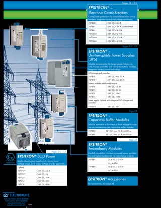
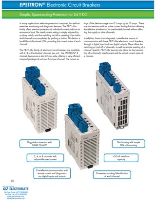
15
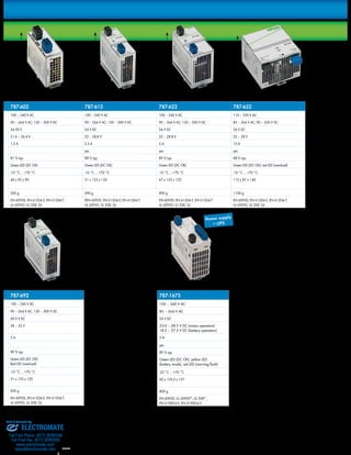
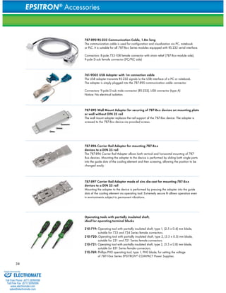
All COMPACT Power Supplies indicate output voltage availability via green LED. This
allows current operating status to be displayed at a glance.
To supply capacitive loads (e.g., distributed control units or HMI devices) with higher inrush
current, WAGO‘s COMPACT Power Supplies feature constant current characteristic, while
delivering 1.1 times the nominal rated current during overload. For low-ohm short circuits, the
output voltage is reduced to zero and automatically reinstated once the short-circuit has been
eliminated.
The wide range of input voltages of the COMPACT Power Supplies allows feeds of 85 to
264 V AC so devices can operate on different supply networks worldwide without additional
conversion or setting. This feature increases tolerance of voltage fluctuations within a supply
network, increasing reliability.
D 89
H 59 **
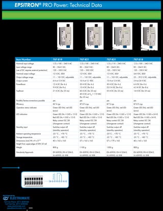
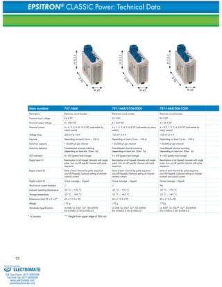
787-1021 787-1017 787-1002 787-1012 787-1022
100 – 240 V AC 100 – 240 V AC 100 – 240 V AC 100 – 240 V AC 100 – 240 V AC
85 – 264 V AC;
85 – 264 V AC;
85 – 264 V AC;
85 – 264 V AC;
85 – 264 V AC;
120 – 373 V DC
120 – 373 V DC
120 – 373 V DC
120 – 373 V DC
120 – 373 V DC
12 V DC 18 V DC 24 V DC 24 V DC 24 V DC
10.5 – 15.5 V DC, adjustable 15 – 19 V DC, adjustable 22.8 – 26.4 V DC, adjustable 22.8 – 26.4 V DC, adjustable 22.8 – 26.4 V DC, adjustable
6.5 A at 12 V DC
2.4 A at 18 V DC
1.3 A at 24 V DC
2.5 A at 24 V DC
4 A at 24 V DC
max. 4 A in any
max. 1.5 A in any
max. 0.9 A in any mounting
max. 1.6 A in any mounting
max. 2.4 A in any mounting
mounting position
mounting position
position
position
position
12 V DC 18 V DC 24 V DC 24 V DC 24 V DC
Constant current, 1.1 x Io typ. Constant current, 1.1 x Io typ. Constant current, 1.1 x Io typ. Constant current, 1.1 x Io typ. Constant current, 1.1 x Io typ.
Green LED (Vo) Green LED (Vo) Green LED (Vo) Green LED (Vo) Green LED (Vo)
87 % typ. 84 % typ. 82 % typ. 88 % typ. 88 % typ.
-25 °C ... +55 °C -25 °C ... +55 °C -25 °C ... +55 °C -25 °C ... +55 °C -25 °C ... +55 °C
-25 °C ... +85 °C -25 °C ... +85 °C -25 °C ... +85 °C -25 °C ... +85 °C -25 °C ... +85 °C
-3 % / K (>45 °C) -3 % / K (>45 °C) -3 % / K (>45 °C) -3 % / K (>45 °C) -3 % / K (>45 °C)
yes yes yes yes yes
DIN-rail mount (EN 60715) DIN-rail mount (EN 60715) DIN-rail mount (EN 60715) DIN-rail mount (EN 60715) DIN-rail mount (EN 60715)
90 x 59 x 89
72 x 59 x 89
54 x 59 x 89
72 x 59 x 89
Height: 55 mm, from upper-edge
Height: 55 mm, from upper-edge
Height: 55 mm,
Height: 55 mm,
of DIN 35 rail
of DIN 35 rail
from upper-edge of DIN 35 rail
from upper-edge of DIN 35 rail
90 x 59 x 89
Height: 55 mm,
from upper-edge of DIN 35 rail
approx. 300 g approx. 240 g approx. 170 g approx. 240 g approx. 300 g
EN 60950 (SELV), EN 61204-3,
EN 60950 (SELV), EN 61204-3,
EN 60950 (SELV), EN 61204-3,
EN 60950 (SELV), EN 61204-3,
UL 60950*, UL 508, GL
UL 60950*, UL 508*
UL 60950, UL 508, GL
UL 60950, UL 508, GL
EN 60950 (SELV), EN 61204-3,
UL 60950, UL 508, GL
Clear Indication
High Load-Carrying Capacity
Universal Supply
H 59 **
H 59 **
H 59 **
H 59 **
D 89
D 89
D 89
D 89
W 72 W 90 W 54 W 72 W 90
Sold & Serviced By:
ELECTROMATE
Toll Free Phone (877) SERVO98
Toll Free Fax (877) SERV099
www.electromate.com
sales@electromate.com](https://image.slidesharecdn.com/wagoepsitronpowersuppliescatalog-141018125429-conversion-gate01/85/Wago-epsitron-power_supplies_catalog-15-320.jpg)
![Iout [%] Ñ
100
24
Constant current
0
0 5 10 15 t [sec] Ñ
Uout [V] Ñ
Overcurrent phase
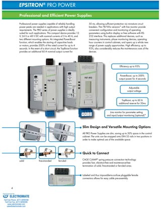
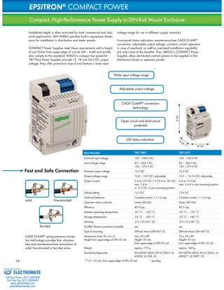
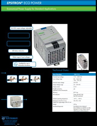
Clear Indication
All ECO Power Supplies have an operating indicator that signals the availability of the output
voltage via a green LED. A red LED indicates an overvoltage. This makes start-up easier and
provides maintenance personnel with quicker information about the machine or system status.
High Load-Carrying Capacity
Loads frequently have an increased need for current at the moment when they are switched
on. The ECO Power Supplies with constant current characteristics deliver 1.1 times the nominal
rated current with lowered output voltage, ideal for starting capacitive loads, for example.
For low-ohm short circuits, the output voltage is reduced to zero and brought up again
automatically as soon as the short circuit has been eliminated.
Universal Supply
The wide range of input voltages of the ECO Power Supplies allows use 90 to 264 V AC. In
addition to the possibility of worldwide use, this increases the tolerance with respect to voltage
fluctuations in the supply, which increases operating reliability.
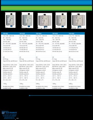
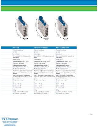
787-722 787-732 787-734 787-736
110 – 240 V AC 110 – 240 V AC 110 – 240 V AC 110 – 240 V AC
85 – 264 V AC;
85 – 264 V AC;
85 – 264 V AC;
130 – 373 V DC
130 – 373 V DC
130 – 373 V DC
85 – 264 V AC;
130 – 373 V DC
24 V DC 24 V DC 24 V DC 24 V DC
22 – 28 V AC 22 – 28 V AC 22 – 28 V AC 22 – 28 V AC
5 A 10 A 20 A 40 A
yes yes yes yes
82 % typ. 82 % typ. 90 % typ. 90 % typ.
Green LED (DC OK)
Green LED (DC OK)
Green LED (DC OK)
Red LED (overload)
Red LED (overload)
Red LED (overload)
Green LED (DC OK)
Red LED (overload)
-10°C ... +60°C -10°C ... +70°C -10°C ... +70°C -10°C ... +70°C
75 x 92 x 130 110 x 92 x 130 115 x 136 x 152 170 x 136 x 150
740 g 1030 g 2400 g 3500 g
EN 60950, EN 61000-6-2,
EN 60950, EN 61000-6-2,
EN 60950, EN 61000-6-2,
EN 61000-6-3,UL 60950, UL 508,
EN 61000-6-3, UL 60950, UL 508,
EN 61000-6-3, UL 60950*, UL 508*
ANSI/ISA 12.12.01 (Class I Div.2),
ANSI/ISA 12.12.01 (Class I Div.2),
ATEX (Zone 2) , IECEx (Zone 2)
ATEX (Zone 2) , IECEx (Zone 2)
EN 60950, EN 61000-6-2,
EN 61000-6-3, UL 60950*, UL 508*
D 130
D 130
H 92
H 92
W 75 W 110
D 136
H 152
W 115
D 136
H 150
W 170
17
Sold & Serviced By:
ELECTROMATE
Toll Free Phone (877) SERVO98
Toll Free Fax (877) SERV099
www.electromate.com
sales@electromate.com](https://image.slidesharecdn.com/wagoepsitronpowersuppliescatalog-141018125429-conversion-gate01/85/Wago-epsitron-power_supplies_catalog-17-320.jpg)
![19
3.45I1 [A]
3.45I2 [A]
o.c.I3 [A]
OFF I4 [A]
24.3 Ui [V]
Uin
1 2 3 4 5 6 7 8
RxPC TxPC
Uin
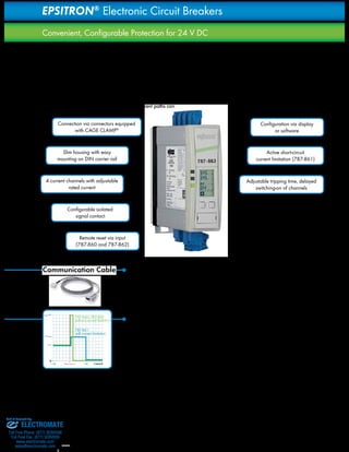
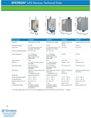
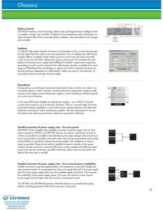
Innovative Communication
1. LEDs: When the device is running and four channels are active, the green LED is
illuminated. Non-critical errors such as minor overcurrents or an undervoltage at the device
input are displayed as warning by the yellow LED, while critical faults such as a circuit
shutting down are indicated by the red LED.
2. Display: The output currents of the 4 channels are indicated continuously on the display
along with the input voltage. Specific devices feature an integrated fault memory for self-diagnostics
in the event of fault conditions.
3. Signal outputs: There are four active signal outputs on the electronic circuit breakers
which function as watch dogs. Direct digital signal processing is used for the outputs. Output
1 is linked to an isolated signal contact on the underside of the 787-860 and 787-862
devices. It can be user-defined via free 759-860 Software even to cover multiple fault
conditions.
4. Interface: The 787-86x electronic circuit breakers can communicate with a PC or
control system via the integrated serial interface. The free 759-860 Software is not only
used to configure the current or tripping characteristics of individual channels, but also for
visualization and fault diagnostic purposes. The 787-890 Serial Communication Cable is
available as an accessory for connection to the RS-232 interface. For more detail on this
feature, see page 32 of this brochure.
H 163
H 163
Item number 787-860 787-862 787-861
Description Electronic circuit breaker Electronic circuit breaker Electronic circuit breaker
Nominal input voltage 24 V DC 24 V DC 24 V DC
Nominal output voltage 4 x 24 V DC 4 x 24 V DC 4 x 24 V DC
Nominal current 4 x 1 – 6 A DC (adjustable for each
channel in 1A steps)
4 x 1 – 10 A DC (adjustable for each
channel in 1A steps)
4 x 1 – 8 A DC (adjustable for each
channel in 1A steps)
Voltage drop 120 mV at 6 A 240 mV at 10 A 240 mV at 8 A
Trip time 100 s (100 ms – 600 s; adjustable) 100 s (100 ms – 600 s; adjustable) 100 ms (100 ms – 1.5 s; adjustable,
depending on nominal current)
Switch-on capacity max. 20,000 μF per channel max. 20,000 μF per channel max. 20,000 μF per channel
Switch-on behavior Time-delayed channel switching (250
ms each)
Time-delayed channel switching (250
ms each)
Time-delayed channel switching (250
ms each)
LED indication LED, LCD, 4 x signal output 24 V DC,
25 mA and 1 x isolated relay contact
60 V DC, 3 A
LED, LCD, 4 x signal output 24 V DC,
25 mA and 1 x isolated relay contact
60 V DC, 3 A
LED, LCD, 4 x signal output 24 V DC,
25 mA
Remote control input Reactivation of all tripped channels
via pulse.
Reactivation of all tripped channels
via pulse.
Short-circuit current limitation -/- -/- 1.5 x nominal current typ.
Ambient operating temperature -10 °C ... +60 °C -10 °C ... +60 °C -10 °C ... +60 °C
Storage temperature -25 °C ... +85 °C -25 °C ... +85 °C -25 °C ... +85 °C
Dimensions (mm) W x H x D* 40 x 163 x 171 40 x 163 x 171 40 x 163 x 171
Weight 800 g 800 g 800 g
Standards/Specifications EN 60950, UL 60950, UL 508,
EN 61000-6-2, EN 61000-6-3
EN 60950, UL 60950, UL 508,
EN 61000-6-2, EN 61000-6-3
EN 60950, UL 60950, UL 508,
EN 61000-6-2, EN 61000-6-3
* H from upper-edge of DIN 35 rail; D=127 mm, without pluggable female connectors (787-860, -862, -861 only)
H 163
D 171
D 171
D 171
W 40 W 40 W 40
Sold & Serviced By:
ELECTROMATE
Toll Free Phone (877) SERVO98
Toll Free Fax (877) SERV099
www.electromate.com
sales@electromate.com](https://image.slidesharecdn.com/wagoepsitronpowersuppliescatalog-141018125429-conversion-gate01/85/Wago-epsitron-power_supplies_catalog-19-320.jpg)
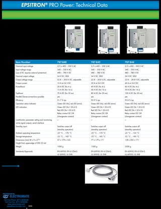
![24
EPSITRON® – Uninterruptible Power Supply (UPS)
Reliable and Safe Compensation – Even for Longer Power Failures
Unpredictable power failures are a nightmare for any machine or
equipment operator. If a PLC is suddenly shut down due to a power
failure, loss of production data (i.e., formulations or protocols) may
follow. To prevent these losses, the Uninterruptible Power Supply,
consisting of UPS charger and controller (787-870 or 787-875) and
one or more connected batteries, reliably power the application for
several hours.
The charging voltage for the connected battery is temperature-controlled,
significantly extending the battery‘s service life and
minimizing maintenance costs. The UPS module supports a complete
current and voltage monitoring while featuring numerous signaling
options via display and RS-232 interface.
Temperature-controlled
charging voltage
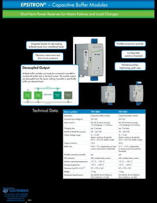
* Fast, clearly labeled connections, see page 4
** Slim design and versatile mounting options, see page 4
Uin
1 2 3 4 5 6 7 8
RxPC TxPC
Uin
787-890
25.4
!!!
Ui [V]
24.6 Uo [V]
8.03 Io [A]
25.4
!!!
Ui [V]
24.6 Uo [V]
8.03 Io [A]
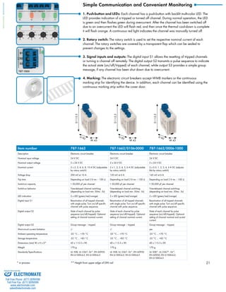
Slim housing that‘s easy
to mount on DIN-rail **
Configurable isolated
signal contact
Three active signal outputs
for watchdog functions
Configuration via display
or software
Battery control technology for pre-dictive
maintenance applications
1. LEDs: A green LED signals error-free operation. Non-critical errors are indicated
as warnings by the yellow LED; the red LED indicates critical errors.
2. Display: All currents and voltages are indicated continuously on the display.
Important parameter settings can be easily performed via on-unit keys. The device
features integrated fault memory for diagnosing errors.
3. Signal outputs: The function monitoring has three active signal outputs that can
be processed as a digital signal and one isolated signal contact coupled with sig-nal
output 1. It can be user-defined (e.g., as a group error signal) via free 759-870
Configuration Software available at www.wago.us.
4. RS-232 serial interface: This interface allows the UPS charger and controller
to communicate with a PC or PLC. In addition to the visualization of relevant data, it
also provides reaction to errors. Parameter setting can also be easily performed via
this interface. The 787-890 Serial Communication Cable is available as an acces-sory
for connection to the RS-232 interface.
Reliability via connectors equipped
with CAGE CLAMP®*
Innovative Communication
Sold & Serviced By:
ELECTROMATE
Toll Free Phone (877) SERVO98
Toll Free Fax (877) SERV099
www.electromate.com
sales@electromate.com](https://image.slidesharecdn.com/wagoepsitronpowersuppliescatalog-141018125429-conversion-gate01/85/Wago-epsitron-power_supplies_catalog-24-320.jpg)
![25
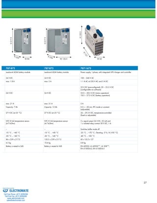
EPSITRON® 787-1675 Power Supply with integrated UPS charger and controller
is designed for applications with lower output requirements. Combined with one
or more connected batteries, this UPS delivers up to 5A output current. Buffer time
can be set on-site via rotary switch and signal contacts provide current operat-ing
25.4
!!!
Ui [V]
24.6Uo [V]
8.03Io [A]
25.4
!!!
Ui [V]
24.6 Uo [V]
8.03 Io [A]
Easy and Compact
status information. The integrated serial interface allows configuration via
software and communication with a PC or PLC.
Predictive Maintenance via Battery Control
EPSITRON® battery control technology allows data exchange between
intelligent battery modules, charger and controller.
The type of connected battery module can be identified, permitting
both temperature and service life of the battery module to be
determined. The advantages are obvious:
••Reliable early warning of decreasing battery life
••Maximum battery life via temperature-controlled
battery management
••Automatic detection of a connected battery module
Service life is determined according to the ambient operating tempera-ture.
This allows faster aging at high ambient operating temperature
to be taken into account, while providing a reliable evaluation of the
residual battery life.
Furthermore, both 787-870 and 787-875 UPS Chargers and Control-lers
display the current charging status, allowing fast detection of the
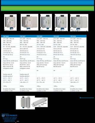
Buffer Time vs. Load Current
787-871
787-873
1 A 3 A 5 A 7 A 9 A 11 A 13 A 15 A 17 A 19 A
1000
100
10
0,1
Buffer time (minutes)
Buffer current
787-876
787-872
UPS status at a glance.
1
Different buffer times/currents can be
achieved depending on the battery module
selected.
Parallel connection of up to 3 battery modules
of the same type increases capacity and
buffer time. However, automatic capacity rec-ognition
must be deactivated in the charger
and controller.
Sold & Serviced By:
ELECTROMATE
Toll Free Phone (877) SERVO98
Toll Free Fax (877) SERV099
www.electromate.com
sales@electromate.com](https://image.slidesharecdn.com/wagoepsitronpowersuppliescatalog-141018125429-conversion-gate01/85/Wago-epsitron-power_supplies_catalog-25-320.jpg)

This document describes the EPSITRON line of advanced power supplies sold and serviced by ELECTROMATE. It provides details on the PRO, COMPACT, CLASSIC, ECO, and UPS power supply series, which offer single or three-phase power with output voltages of 12V, 24V, 30.5V and 48V and currents ranging from 1A to 40A. It also describes accessories like redundancy modules, circuit breakers, and capacitive buffer modules that can be used with the power supplies.


