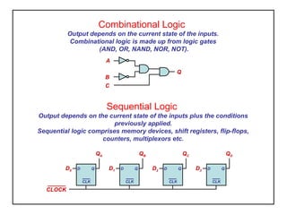
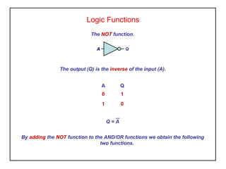
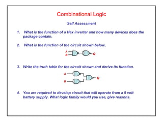
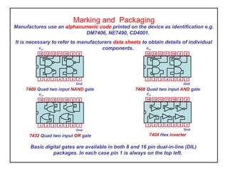
Digital Components – Basic Gates
Although digital logic circuits are active devices they form a separate family
to linear devices such as transistors and operational amplifiers since
they have only two states – ‘on or off’ known as 1 or 0, true or false.
TTL
Transistor-Transistor Logic uses bipolar transistor technology
7400 series. LS is a low power fast variant, ie 74LS00.
TTL devices operate from a nominal 5 volt dc supply (4.75 to 5.25V)
Very fast but require considerable power, not suitable for portable battery
operated equipment, not static sensitive.
CMOS
Complementary Metal Oxide Semiconductor using MOSFET technology, 4000
series.
Operating voltage for CMOS is 3 to 15 volts.
Very low power consumption making them ideal for portable equipment.
Handling precautions must be taken when working with CMOS as they
are sensitive to static electricity.
Both families are available as 14 and 16 pin Dual In Line (DIL) and surface
mount packages.
Sequential Logic
Output depends on the current state of the inputs plus the conditions
previously applied.
Sequential logic comprises memory devices, shift registers, flip-flops,
counters, multiplexors etc.
Combinational Logic
Output depends on the current state of the inputs.
Combinational logic is made up from logic gates
(AND, OR, NAND, NOR, NOT).
A
B
C
Q
D Q
CLK
QA
D0 D Q
CLK
QB
D1 D Q
CLK
QC
D2 D Q
CLK
QD
D3
CLOCK
Logic Functions
The AND function.
A
B
Q
The output (Q) is true (1) providing both inputs (A AND B) are true.
A B Q
0 0 0
0 1 0
1 0 0
1 1 1
Q = A.B
Logic Functions
Activity - Verifying the AND function
1. Connect the power supply to the device (pin 14 to +5V , pin 7 to 0V)
2. Connect a LED to the output (Q pin 3)
3. Write the truth table below
4. By connecting each input to 5v (1) or 0v (0) complete the output section (Q) for
the LED conditions
5. From your results state in words the input conditions for the LED to be ‘ON’.
A(1)
B(2)
Q(3)
LED
condition
Logic Functions
Activity - Verifying Logic Functions
1. Connect the power supply to the device (pin 14 to +5V , pin 7 to 0V)
2. Connect a LED to the output (Q pin 3)
3. Write the truth table below
4. By connecting each input to 5v (1) or 0v (0) complete the output section
(Q) for the LED conditions
5. From your results state in words the conditions for the LED to be ‘ON’.
LED
condition
A(1)
B(2)
Q(3)
?
Primary Logic Functions
A B Q
0 0 0
0 1 1
1 0 1
1 1 1
The OR function
Q = A + B
Q
A
B
A B Q
0 0 0
0 1 0
1 0 0
1 1 1
The AND function
A
B
Q
Q = A.B
A Q
0 1
1 0
The NOT function.
QAA
Q = A
Secondary Logic Functions
A B Q
0 0 1
0 1 1
1 0 1
1 1 0
The NAND function
A
B
Q
Q = A.B
A B Q
0 0 1
0 1 0
1 0 0
1 1 0
The NOR function
Q = A + B
Q
A
B
Combinational Logic Functions
74LS08
Using the devices stated, connect
the circuit as shown
74LS04
Activity – Logic Circuit
74LS32
Q
A
B
3
2
1
3
2
1
6
5
4
1 2
3 4
Test your circuit and produce the truth
table.
State in words the input conditions to
produce a ‘1’ at the output.
Logic Functions
The XOR function (Exclusive OR).
A B Q
0 0 0
0 1 1
1 0 1
1 1 0
The output (Q) is true (1) when each input is different.
Q = A.B + A.B
Q
A
B
Q = A + B
Logic Functions
The OR function.
A B Q
0 0 0
0 1 1
1 0 1
1 1 1
The output (Q) is true (1) when either or both inputs (A OR B) are true (1).
Q = A + B
Q
A
B
Logic Functions
The NOT function.
The output (Q) is the inverse of the input (A).
A Q
0 1
1 0
QAA
By adding the NOT function to the AND/OR functions we obtain the following
two functions.
Q = A
Logic Functions
The NAND function.
A B Q
0 0 1
0 1 1
1 0 1
1 1 0
A
B
Q
The output (Q) is true (1) if any input is false (0).
Q = A.B
Logic Functions
The NOR function.
A B Q
0 0 1
0 1 0
1 0 0
1 1 0
The output (Q) is false (0) when either or both inputs (A OR B) are true (1).
Q = A + B
Q
A
B
Logic Functions
The XOR function (Exclusive OR).
A B Q
0 0 0
0 1 1
1 0 1
1 1 0
The output (Q) is true (1) when each input is different.
Q = A.B + A.B
Q
A
B
Q = A + B
Logic Functions
The X-NOR function (Exclusive NOR).
A B Q
0 0 1
0 1 0
1 0 0
1 1 1
The output (Q) is true (1) when both inputs are the same.
Q = A + B
Q
A
B
Q = A.B + A.B
Combinational Logic
A
B Q
Self Assessment
1. What is the function of a Hex inverter and how many devices does the
package contain.
2. What is the function of the circuit shown below,
3. Write the truth table for the circuit shown and derive its function.
4. You are required to develop circuit that will operate from a 9 volt
battery supply. What logic family would you use, give reasons.
A
B
Q
Combinational Logic
Generating a Truth Table
To write a truth table for a combinational logic circuit we must follow the
steps below
• Write up all the possible input combinations
• Label each of the gate functions in terms of its inputs
• Provide a column to represent each of the gate functions in the circuit
• Complete the table in terms of the input variables to each gate function
A B Q
0 0 1 1 1 0
0 1 1 1 0 1
1 0 1 0 1 1
1 1 0 1 1 0
AB (A) (AB) (B) (AB)
AB
A
B
Q
(A) (AB)
(B) (AB)
What function is this ?
Combinational Logic
Activity
Construct the truth tables for the circuits shown
A
B
QC
QA
B
Basic digital gates are available in both 8 and 16 pin dual-in-line (DIL)
packages. In each case pin 1 is always on the top left.
Marking and Packaging
Manufactures use an alphanumeric code printed on the device as identification e.g.
DM7406, NE7490, CD4001.
It is necessary to refer to manufacturers data sheets to obtain details of individual
components.
7404 Hex inverter
1 2 3 4 5 6 7
14 13 12 11 10 9 8
VCC
Gnd
7408 Quad two input AND gate
1 2 3 4 5 6 7
14 13 12 11 10 9 8
VCC
Gnd
7400 Quad two input NAND gate
1 2 3 4 5 6 7
14 13 12 11 10 9 8
VCC
Gnd
7404 Hex inverter
1 2 3 4 5 6 7
14 13 12 11 10 9 8
VCC
Gnd
7408 Quad two input AND gate
1 2 3 4 5 6 7
14 13 12 11 10 9 8
VCC
Gnd
7432 Quad two input OR gate
1 2 3 4 5 6 7
14 13 12 11 10 9 8
VCC
Gnd

Components logic gates

  • 1.
    Digital Components –Basic Gates Although digital logic circuits are active devices they form a separate family to linear devices such as transistors and operational amplifiers since they have only two states – ‘on or off’ known as 1 or 0, true or false. TTL Transistor-Transistor Logic uses bipolar transistor technology 7400 series. LS is a low power fast variant, ie 74LS00. TTL devices operate from a nominal 5 volt dc supply (4.75 to 5.25V) Very fast but require considerable power, not suitable for portable battery operated equipment, not static sensitive. CMOS Complementary Metal Oxide Semiconductor using MOSFET technology, 4000 series. Operating voltage for CMOS is 3 to 15 volts. Very low power consumption making them ideal for portable equipment. Handling precautions must be taken when working with CMOS as they are sensitive to static electricity. Both families are available as 14 and 16 pin Dual In Line (DIL) and surface mount packages.
  • 2.
    Sequential Logic Output dependson the current state of the inputs plus the conditions previously applied. Sequential logic comprises memory devices, shift registers, flip-flops, counters, multiplexors etc. Combinational Logic Output depends on the current state of the inputs. Combinational logic is made up from logic gates (AND, OR, NAND, NOR, NOT). A B C Q D Q CLK QA D0 D Q CLK QB D1 D Q CLK QC D2 D Q CLK QD D3 CLOCK
  • 3.
    Logic Functions The ANDfunction. A B Q The output (Q) is true (1) providing both inputs (A AND B) are true. A B Q 0 0 0 0 1 0 1 0 0 1 1 1 Q = A.B
  • 4.
    Logic Functions Activity -Verifying the AND function 1. Connect the power supply to the device (pin 14 to +5V , pin 7 to 0V) 2. Connect a LED to the output (Q pin 3) 3. Write the truth table below 4. By connecting each input to 5v (1) or 0v (0) complete the output section (Q) for the LED conditions 5. From your results state in words the input conditions for the LED to be ‘ON’. A(1) B(2) Q(3) LED condition
  • 5.
    Logic Functions Activity -Verifying Logic Functions 1. Connect the power supply to the device (pin 14 to +5V , pin 7 to 0V) 2. Connect a LED to the output (Q pin 3) 3. Write the truth table below 4. By connecting each input to 5v (1) or 0v (0) complete the output section (Q) for the LED conditions 5. From your results state in words the conditions for the LED to be ‘ON’. LED condition A(1) B(2) Q(3) ?
  • 6.
    Primary Logic Functions AB Q 0 0 0 0 1 1 1 0 1 1 1 1 The OR function Q = A + B Q A B A B Q 0 0 0 0 1 0 1 0 0 1 1 1 The AND function A B Q Q = A.B A Q 0 1 1 0 The NOT function. QAA Q = A
  • 7.
    Secondary Logic Functions AB Q 0 0 1 0 1 1 1 0 1 1 1 0 The NAND function A B Q Q = A.B A B Q 0 0 1 0 1 0 1 0 0 1 1 0 The NOR function Q = A + B Q A B
  • 8.
    Combinational Logic Functions 74LS08 Usingthe devices stated, connect the circuit as shown 74LS04 Activity – Logic Circuit 74LS32 Q A B 3 2 1 3 2 1 6 5 4 1 2 3 4 Test your circuit and produce the truth table. State in words the input conditions to produce a ‘1’ at the output.
  • 9.
    Logic Functions The XORfunction (Exclusive OR). A B Q 0 0 0 0 1 1 1 0 1 1 1 0 The output (Q) is true (1) when each input is different. Q = A.B + A.B Q A B Q = A + B
  • 10.
    Logic Functions The ORfunction. A B Q 0 0 0 0 1 1 1 0 1 1 1 1 The output (Q) is true (1) when either or both inputs (A OR B) are true (1). Q = A + B Q A B
  • 11.
    Logic Functions The NOTfunction. The output (Q) is the inverse of the input (A). A Q 0 1 1 0 QAA By adding the NOT function to the AND/OR functions we obtain the following two functions. Q = A
  • 12.
    Logic Functions The NANDfunction. A B Q 0 0 1 0 1 1 1 0 1 1 1 0 A B Q The output (Q) is true (1) if any input is false (0). Q = A.B
  • 13.
    Logic Functions The NORfunction. A B Q 0 0 1 0 1 0 1 0 0 1 1 0 The output (Q) is false (0) when either or both inputs (A OR B) are true (1). Q = A + B Q A B
  • 14.
    Logic Functions The XORfunction (Exclusive OR). A B Q 0 0 0 0 1 1 1 0 1 1 1 0 The output (Q) is true (1) when each input is different. Q = A.B + A.B Q A B Q = A + B
  • 15.
    Logic Functions The X-NORfunction (Exclusive NOR). A B Q 0 0 1 0 1 0 1 0 0 1 1 1 The output (Q) is true (1) when both inputs are the same. Q = A + B Q A B Q = A.B + A.B
  • 16.
    Combinational Logic A B Q SelfAssessment 1. What is the function of a Hex inverter and how many devices does the package contain. 2. What is the function of the circuit shown below, 3. Write the truth table for the circuit shown and derive its function. 4. You are required to develop circuit that will operate from a 9 volt battery supply. What logic family would you use, give reasons. A B Q
  • 17.
    Combinational Logic Generating aTruth Table To write a truth table for a combinational logic circuit we must follow the steps below • Write up all the possible input combinations • Label each of the gate functions in terms of its inputs • Provide a column to represent each of the gate functions in the circuit • Complete the table in terms of the input variables to each gate function A B Q 0 0 1 1 1 0 0 1 1 1 0 1 1 0 1 0 1 1 1 1 0 1 1 0 AB (A) (AB) (B) (AB) AB A B Q (A) (AB) (B) (AB) What function is this ?
  • 18.
    Combinational Logic Activity Construct thetruth tables for the circuits shown A B QC QA B
  • 19.
    Basic digital gatesare available in both 8 and 16 pin dual-in-line (DIL) packages. In each case pin 1 is always on the top left. Marking and Packaging Manufactures use an alphanumeric code printed on the device as identification e.g. DM7406, NE7490, CD4001. It is necessary to refer to manufacturers data sheets to obtain details of individual components. 7404 Hex inverter 1 2 3 4 5 6 7 14 13 12 11 10 9 8 VCC Gnd 7408 Quad two input AND gate 1 2 3 4 5 6 7 14 13 12 11 10 9 8 VCC Gnd 7400 Quad two input NAND gate 1 2 3 4 5 6 7 14 13 12 11 10 9 8 VCC Gnd 7404 Hex inverter 1 2 3 4 5 6 7 14 13 12 11 10 9 8 VCC Gnd 7408 Quad two input AND gate 1 2 3 4 5 6 7 14 13 12 11 10 9 8 VCC Gnd 7432 Quad two input OR gate 1 2 3 4 5 6 7 14 13 12 11 10 9 8 VCC Gnd