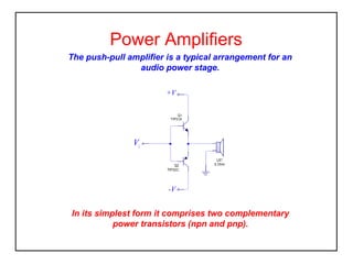
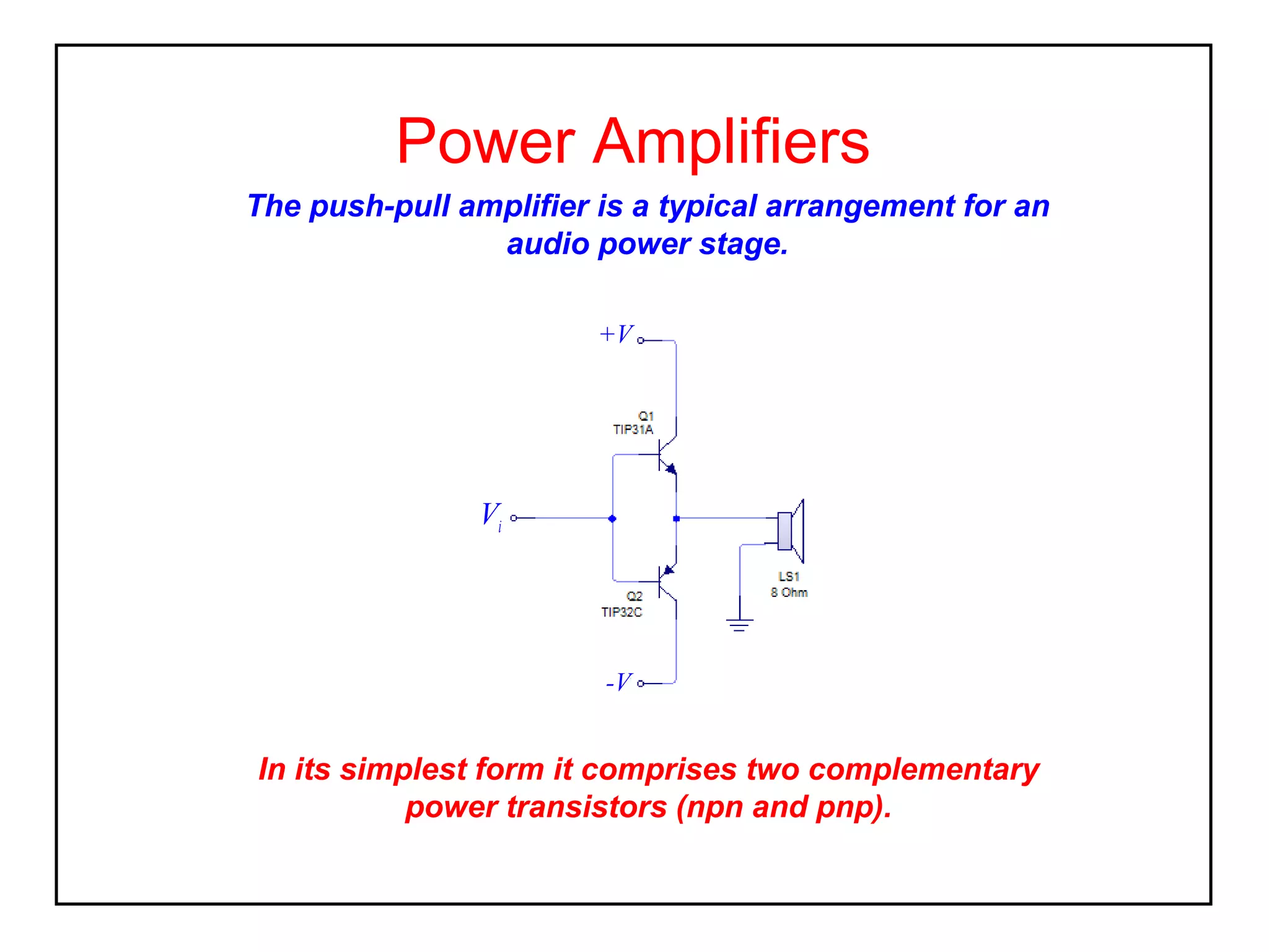
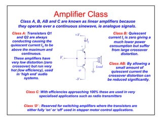
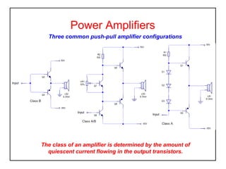
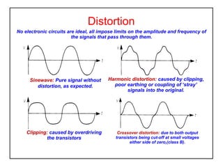
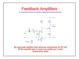
Power Amplifiers
The push-pull amplifier is a typical arrangement for an
audio power stage.
+V

Vi

-V

In its simplest form it comprises two complementary
power transistors (npn and pnp).
Amplifier Class
Class A, B, AB and C are known as linear amplifiers because
they operate over a continuous sinewave, ie analogue signals.
Class A: Transistors Q1
and Q2 are always
conducting causing the
quiescent current IQ to be
above the maximum and
continuous.
These amplifiers have
very low distortion (zero
crossover) but run very
hot (low efficiency), used
in ‘high end’ audio
systems.

Class B: Quiescent
current IQ is zero giving a
much lower power
consumption but suffer
from large crossover
distortion.

+V

IQ
Q1

Vi
Load
Q2

-V

Class AB: By allowing a
small amount of
quiescent current the
crossover distortion can
be reduced significantly.

Class C: With efficiencies approaching 100% these are used in very
specialised applications such as radio transmitters
Class ‘D’ : Reserved for switching amplifiers where the transistors are
either fully ‘on’ or ‘off’ used in stepper motor control applications.
Power Amplifiers
Three common push-pull amplifier configurations

The class of an amplifier is determined by the amount of
quiescent current flowing in the output transistors.
Distortion
No electronic circuits are ideal, all impose limits on the amplitude and frequency of
the signals that pass through them.

Sinewave: Pure signal without
distortion, as expected.

Clipping: caused by overdriving
the transistors

Harmonic distortion: caused by clipping,
poor earthing or coupling of ‘stray’
signals into the original.

Crossover distortion: due to both output
transistors being cut-off at small voltages
either side of zero,(class B).
Amplifier Bandwidth
The cut-off frequencies, f1 and f2, define the bandwidth
Bandwidth = f2 – f1

Gain
dB
Am

bandwidth

f1

f2

frequency
Hz

Am is called the midband gain, which in an ideal amplifier is flat through the
frequency range, as above.
The operational gain is called the bandwidth and is the gain between the cut-off frequencies f1 and f2, also known
as the half-power points or -3dB points.
Feedback Amplifiers
By using feedback the gain of an amplifier is independent of transistor parameters

RI

RF

By using high stability close tolerance components for R1 and
R2 the amplifier gain is made very stable over a wide
temperature range
Gain Bandwidth Product
The GB product is a term that quantatively states the
performance of an amplifier.
Gain dB 100
80
60
-20dB/decade

40
20
1
0

1

10

100 1000 10000

100000 f Hz.

This quantity is commonly specified for operational amplifiers, and allows
circuit designers to determine the maximum gain that can be achieved
from the device for a given frequency (or bandwidth) and vice versa.
Effects of Feedback
Negative feedback is widely used in amplifier circuits for the
following reasons,
•gain is independent of transistor parameters
•Can increase or decrease input impedance (depending on type
of feedback)
•Can increase or decrease output impedance (depending on type
of feedback)
•Reduces distortion (increases linearity)
•Bandwidth is increased

Ways to apply feedback; series voltage (voltage amplifier), series current
(transconductance amplifier), ; shunt current (current amplifier), shunt
voltage (transresistance amplifier).

Electronics amplifiers

  • 1.
    Power Amplifiers The push-pullamplifier is a typical arrangement for an audio power stage. +V Vi -V In its simplest form it comprises two complementary power transistors (npn and pnp).
  • 2.
    Amplifier Class Class A,B, AB and C are known as linear amplifiers because they operate over a continuous sinewave, ie analogue signals. Class A: Transistors Q1 and Q2 are always conducting causing the quiescent current IQ to be above the maximum and continuous. These amplifiers have very low distortion (zero crossover) but run very hot (low efficiency), used in ‘high end’ audio systems. Class B: Quiescent current IQ is zero giving a much lower power consumption but suffer from large crossover distortion. +V IQ Q1 Vi Load Q2 -V Class AB: By allowing a small amount of quiescent current the crossover distortion can be reduced significantly. Class C: With efficiencies approaching 100% these are used in very specialised applications such as radio transmitters Class ‘D’ : Reserved for switching amplifiers where the transistors are either fully ‘on’ or ‘off’ used in stepper motor control applications.
  • 3.
    Power Amplifiers Three commonpush-pull amplifier configurations The class of an amplifier is determined by the amount of quiescent current flowing in the output transistors.
  • 4.
    Distortion No electronic circuitsare ideal, all impose limits on the amplitude and frequency of the signals that pass through them. Sinewave: Pure signal without distortion, as expected. Clipping: caused by overdriving the transistors Harmonic distortion: caused by clipping, poor earthing or coupling of ‘stray’ signals into the original. Crossover distortion: due to both output transistors being cut-off at small voltages either side of zero,(class B).
  • 5.
    Amplifier Bandwidth The cut-offfrequencies, f1 and f2, define the bandwidth Bandwidth = f2 – f1 Gain dB Am bandwidth f1 f2 frequency Hz Am is called the midband gain, which in an ideal amplifier is flat through the frequency range, as above. The operational gain is called the bandwidth and is the gain between the cut-off frequencies f1 and f2, also known as the half-power points or -3dB points.
  • 6.
    Feedback Amplifiers By usingfeedback the gain of an amplifier is independent of transistor parameters RI RF By using high stability close tolerance components for R1 and R2 the amplifier gain is made very stable over a wide temperature range
  • 7.
    Gain Bandwidth Product TheGB product is a term that quantatively states the performance of an amplifier. Gain dB 100 80 60 -20dB/decade 40 20 1 0 1 10 100 1000 10000 100000 f Hz. This quantity is commonly specified for operational amplifiers, and allows circuit designers to determine the maximum gain that can be achieved from the device for a given frequency (or bandwidth) and vice versa.
  • 8.
    Effects of Feedback Negativefeedback is widely used in amplifier circuits for the following reasons, •gain is independent of transistor parameters •Can increase or decrease input impedance (depending on type of feedback) •Can increase or decrease output impedance (depending on type of feedback) •Reduces distortion (increases linearity) •Bandwidth is increased Ways to apply feedback; series voltage (voltage amplifier), series current (transconductance amplifier), ; shunt current (current amplifier), shunt voltage (transresistance amplifier).