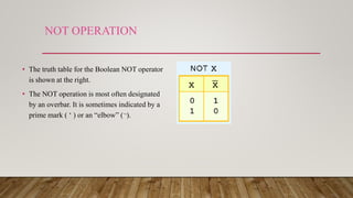
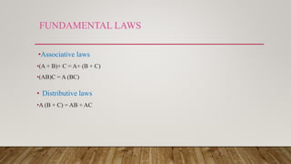
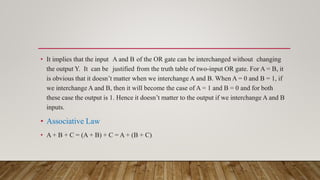
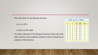
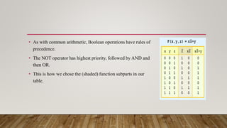
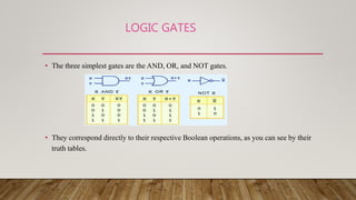
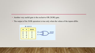
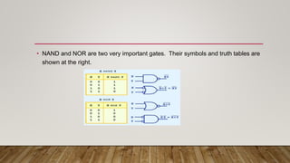
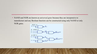
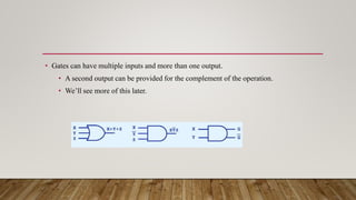
The document covers the fundamentals of logic gates and circuits, highlighting the connection between boolean logic and digital computer circuits, as well as the importance of simplifying boolean functions for efficient circuit design. It discusses various boolean operations, laws, and the significance of different logic gates, including AND, OR, NOT, NAND, and NOR. Additionally, it explains characteristics of logic families and various types of bipolar transistor families used in integrated circuits.


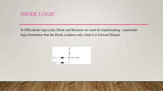
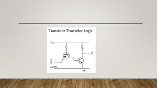
![BIPOLAR FAMILIES
• Bipolar transistors are fabricated on a chip in digital integrated circuits.
• Bipolar technology is preferred for SSI[Small scale integrated]and MS[Medium scale
integration]because it is faster.
• TYPES OF BIPOLAR FAMILIES:
• Diode Logic(DL)
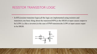
• Register Transistor Logic(RTL)
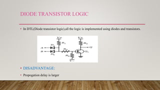
• Diode Transistor Logic
• Transistor-Transistor Logic](https://image.slidesharecdn.com/unit2-200224145556/85/Logic-gates-and-circuits-24-320.jpg)


![De Morgan Theorem B[1]](https://cdn.slidesharecdn.com/ss_thumbnails/demorgantheoremb1-090930110355-phpapp01-thumbnail.jpg?width=640&height=640&fit=bounds)


![Chapter 3 computer Boolean Algebra 2[1].pptx](https://cdn.slidesharecdn.com/ss_thumbnails/chapter3booleanalgebra21-240928031107-5861eb7e-thumbnail.jpg?width=640&height=640&fit=bounds)