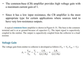
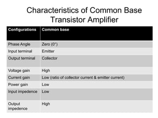
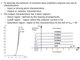
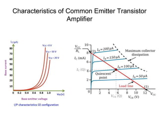
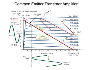
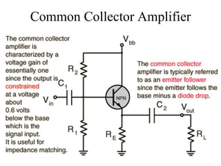
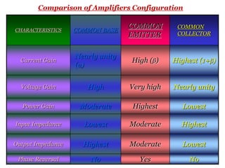
The document discusses different configurations of bipolar transistors in electronic circuits: common base, common emitter, and common collector. Each configuration has different characteristics in terms of current gain, voltage gain, power gain, input/output impedance, and phase reversal. The common base configuration has voltage gain but no current gain. The common emitter configuration has both current and voltage gain. The common collector configuration has current gain but no voltage gain.
This presentation contains the basic information you need to know about operational amplifier.
I have tried to cover all the basic info. If anything is left out or you have any suggestions i will appreciate it.
Power Amplifier circuits.
Output stages of types of power amplifier (class A, class B, class AB, class C, class D)
Distortions( Harmonic and Crossover).
Push-pull amplifier with and without transformer.
Complimentary symmetry and Quasi- complimentary symmetry push pull amplifier.
Multistage amplifiers and Name of coupling Name of multistage amplifierimtiazalijoono
MULTISTAGE AMPLIFIERS
Name of coupling Name of multistage amplifier
1) RC coupling R-C coupled amplifier
2) Transformer coupling Transformer coupled amplifier
3) Direct coupling Direct coupled amplifier
A Bipolar Junction Transistor is a three-terminal semiconductor device consisting of two p-n junctions which are able to amplify or magnify a signal. It is a current controlled device. The three terminals of the BJT are the base, the collector and the emitter. A BJT is a type of transistor that uses both electrons and holes as charge carriers
This Presentation can be used by the Students of Engineering who Deals with the Subject Electronics Devices and Circuits and use it for Refrence (Anyways you Guys will Copy Paste or Download it) ;)
2. As the Bipolar Transistor is a three-terminal device, there are
basically three possible ways to connect it within an electronic circuit
with one terminal being common to both the input and output. Each
method of connection responding differently to its input signal within
a circuit as the static characteristics of the transistor vary with each
circuit arrangement.
• Common Base Configuration – has Voltage Gain but no
Current Gain
• Common Emitter Configuration – has both Current and
Voltage Gain
• Common Collector Configuration – has Current Gain but no
Voltage Gain
4. • The common-base (CB) amplifier provides high voltage gain with
a maximum current gain of 1.
• Since it has a low input resistance, the CB amplifier is the most
appropriate type for certain applications where sources tend to
have very low-resistance outputs.
5.
6.
7.
8. Characteristics of Common Base
Transistor Amplifier
Configurations Common base
Phase Angle Zero (0°)
Input terminal Emitter
Output terminal Collector
Voltage gain High
Current gain Low (ratio of collector current & emitter current)
Power gain Low
Input impedence Low
Output
impedence
High
9. • To describe the behavior of common-base amplifiers requires two set of
characteristics:
- Input or driving point characteristics.
- Output or collector characteristics
• The output characteristics has 3 basic regions:
- Active region –defined by the biasing arrangements
- Cutoff region – region where the collector current is 0A
- Saturation region- region of the characteristics to the left of VCB = 0V
10.
11. Alpha():
• In the dc mode the level of IC and IE due to the
majority carriers are related by a quantity called alpha
=
So,
IC = IE
• For ac situations where the point of operation moves on
the characteristics curve, an ac alpha defined by
• Alpha a common base current gain factor that shows
the efficiency by calculating the current percent from
current flow from emitter to collector. The value of is
typical from 0.9 ~ 0.998.
E
C
I
I
E
C
I
I
25. • The common-collector (CC) amplifier is usually
referred to as an emitter-follower (EF).
• The input is applied to the base through a
coupling capacitor, and the output is at the
emitter.
• The voltage gain of a CC amplifier is
approximately 1, and its main advantages are its
high input resistance and current gain.
26. • An emitter-follower circuit with voltage-divider
bias is shown in Figure 6–25.
• Notice that the input signal is capacitively coupled
to the base, the output signal is capacitively
coupled from the emitter, and the collector is at ac
ground.
• There is no phase inversion, and the output is
approximately the same amplitude as the input.
33. CHARACTERISTICS COMMON BASE
COMMON
EMITTER
COMMON
COLLECTOR
Current Gain
Nearly unity
(α)
High (β) Highest (1+β)
Voltage Gain High Very high Nearly unity
Power Gain Moderate Highest Lowest
Input Impedance Lowest Moderate Highest
Output Impedance Highest Moderate Lowest
Phase Reversal No Yes No
Comparison of Amplifiers Configuration