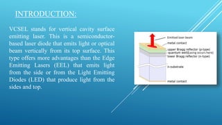
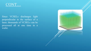
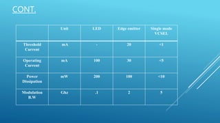
VERTICAL CAVITY SURFACE EMITTING LASERS
(VCSELS)
BY TAFHIM BIN NASIR
INTRODUCTION:
VCSEL stands for vertical cavity surface
emitting laser. This is a semiconductor-
based laser diode that emits light or optical
beam vertically from its top surface. This
type offers more advantages than the Edge
Emitting Lasers (EEL) that emits light
from the side or from the Light Emitting
Diodes (LED) that produce light from the
sides and top.
CONT…
Since VCSELs discharges light
perpendicular to the surface of a
laser, thousands of VCSELs can be
processed all at one time in a
wafer.
WHY SURFACE EMITTING LASER ?
• There are several advantages to producing VCSELs when compared with the production process of
edge-emitting lasers.
• Edge-emitters cannot be tested until the end of the production process. If the edge-emitter does not
work, whether due to bad contacts or poor material growth quality, the production time and the
processing materials have been wasted.
• VCSELs , however, can be tested at several stages throughout the process to check for material
quality and processing issues.
CONT.
Unit LED Edge emitter Single mode
VCSEL
Threshold
Current
mA - 20 <1
Operating
Current
mA 100 30 <5
Power
Dissipation
mW 200 100 <10
Modulation
B.W
Ghz .1 2 5
HISTORY OF VCSEL RESEARCH :
• It is recognized that Mr Iga suggested VCSELin 1977.
• The first VCSEL was presented in 1979 by Soda, Iga, Kitahara and
Suematsu (Soda 1979), where the 1.3 um-wavelength GaInAsP/InP
material was used for the active region.
• In 1986 a 6-mA thereshold GaAs device was made by that group.
• In 1989, Jack Jewell demonstrated an InGaAs SE laser exhibiting 2-
mAthreshold.
• Today, VCSELs have replaced edge-emitting lasers in applications for
short-range fiber optic communication such as Gigabit Ethernet and Fiber
Channel
CONT.
CONT.
Following figure shows the improvement in the electric to optical power conversion (or
“wall-plug”) efficiency versus year:
MATERIAL AND WAVELENGTH OF VCSELS :
• AlGaInP/AlGaAs for Red wavelength (650-680nm)VCSELs
• GaInAsP/AlGaAs for Near-IR wavelength (780-850nm)VCSELs
• AlGaInAs for wavelength 850nmVCSELs
• GaInAsN for Long-wavelength (1.3-1.55um)VCSELs
• Sb for Long-wavelength (1.3-1.55um)VCSELs
• III-V Nitride for Visible wavelength VCSELs
STRUCTURE :
• Two distributed Bragg reflector (DBR) mirrors parallel to the
wafer surface with an active region consisting of one or more
quantum wells for the laser light generation in between.
• The planar DBR-mirrors consist of layers with alternating high
and low refractive indices.
• Each layer has a thickness of a quarter of the laser wavelength
in the material, yielding intensity reflectivities above 99%.
• High reflectivity mirrors are required in VCSELs to balance the
short axial length of the gain region.
CONT.
• In common VCSELs the upper and lower mirrors are
doped as p-type and n-type materials, forming a
diode junction.
• VCSELs for wavelengths from 650 nm to 1300 nm
are typically based on (GaAs) wafers with DBRs
formed from GaAs and (AlGaAs).
• Longer wavelength devices, from 1300 nm to 2000
nm, have been demonstrated the active region made
of indium phosphide.
ADVANTAGES OF VCSEL :
• Easier to test on wafer
• Wavelength is “tunable”
• Low current needed due to small active volume
• Circular cross-section that can be easily coupled
• The VCSEL is cheaper to manufacture in quantity
• Efficiency and speed of data transfer is improved for fiber optic communications
• It can be integrated in 2D array configuration.
• Low temperature sensitivity compare to edge emitting laser.
APPLICATION :
• Optical Memory: VCSELs are used to read the data on compact disks and CDROMs
,DVD, Near field
• Optoelectronic: Printer, Laser pointer, Mouse.
• Optical Information Processing: Optical processors, Parallel processing.
• Optical Sensing: Longer wavelength VCSELs for sensor application, Optical fiber sensing,
Bar code readers
• Displays: Shorter wavelength VCSELs for displays, Array light sources, Multi-beam
search lights, High efficiency sources
CONCLUSION :
VCSELs are a relatively recent type of semiconductor laser . But it gained a reputation as
a superior technology for short reach applications such as fiber channel, Ethernet and
intra-systems links. This success was mainly due to the VCSEL’s lower manufacturing
costs and higher reliability compared to edge-emitters . Moreover high transmission speed
with low power consumption is also a good characteristics of VCSEL.
REFERENCES :
• https://en.wikipedia.org/wiki/Vertical-cavity_surface-emitting_laser#Structure
• https://www.rp-photonics.com/vertical_cavity_surface_emitting_lasers.html
• https://www.newmetals.co.jp/pdf/234.pdf
• https://www.slideserve.com/angelina/vcsel
• https://whatis.techtarget.com/definition/vertical-cavity-surface-emitting-laser-VCSEL
THANK YOU

Vertical Cavity Surface Emitting Lasers ( VCSELs )

  • 1.
    VERTICAL CAVITY SURFACEEMITTING LASERS (VCSELS) BY TAFHIM BIN NASIR
  • 2.
    INTRODUCTION: VCSEL stands forvertical cavity surface emitting laser. This is a semiconductor- based laser diode that emits light or optical beam vertically from its top surface. This type offers more advantages than the Edge Emitting Lasers (EEL) that emits light from the side or from the Light Emitting Diodes (LED) that produce light from the sides and top.
  • 3.
    CONT… Since VCSELs dischargeslight perpendicular to the surface of a laser, thousands of VCSELs can be processed all at one time in a wafer.
  • 4.
    WHY SURFACE EMITTINGLASER ? • There are several advantages to producing VCSELs when compared with the production process of edge-emitting lasers. • Edge-emitters cannot be tested until the end of the production process. If the edge-emitter does not work, whether due to bad contacts or poor material growth quality, the production time and the processing materials have been wasted. • VCSELs , however, can be tested at several stages throughout the process to check for material quality and processing issues.
  • 5.
    CONT. Unit LED Edgeemitter Single mode VCSEL Threshold Current mA - 20 <1 Operating Current mA 100 30 <5 Power Dissipation mW 200 100 <10 Modulation B.W Ghz .1 2 5
  • 6.
    HISTORY OF VCSELRESEARCH : • It is recognized that Mr Iga suggested VCSELin 1977. • The first VCSEL was presented in 1979 by Soda, Iga, Kitahara and Suematsu (Soda 1979), where the 1.3 um-wavelength GaInAsP/InP material was used for the active region. • In 1986 a 6-mA thereshold GaAs device was made by that group. • In 1989, Jack Jewell demonstrated an InGaAs SE laser exhibiting 2- mAthreshold. • Today, VCSELs have replaced edge-emitting lasers in applications for short-range fiber optic communication such as Gigabit Ethernet and Fiber Channel
  • 7.
  • 8.
    CONT. Following figure showsthe improvement in the electric to optical power conversion (or “wall-plug”) efficiency versus year:
  • 9.
    MATERIAL AND WAVELENGTHOF VCSELS : • AlGaInP/AlGaAs for Red wavelength (650-680nm)VCSELs • GaInAsP/AlGaAs for Near-IR wavelength (780-850nm)VCSELs • AlGaInAs for wavelength 850nmVCSELs • GaInAsN for Long-wavelength (1.3-1.55um)VCSELs • Sb for Long-wavelength (1.3-1.55um)VCSELs • III-V Nitride for Visible wavelength VCSELs
  • 10.
    STRUCTURE : • Twodistributed Bragg reflector (DBR) mirrors parallel to the wafer surface with an active region consisting of one or more quantum wells for the laser light generation in between. • The planar DBR-mirrors consist of layers with alternating high and low refractive indices. • Each layer has a thickness of a quarter of the laser wavelength in the material, yielding intensity reflectivities above 99%. • High reflectivity mirrors are required in VCSELs to balance the short axial length of the gain region.
  • 11.
    CONT. • In commonVCSELs the upper and lower mirrors are doped as p-type and n-type materials, forming a diode junction. • VCSELs for wavelengths from 650 nm to 1300 nm are typically based on (GaAs) wafers with DBRs formed from GaAs and (AlGaAs). • Longer wavelength devices, from 1300 nm to 2000 nm, have been demonstrated the active region made of indium phosphide.
  • 12.
    ADVANTAGES OF VCSEL: • Easier to test on wafer • Wavelength is “tunable” • Low current needed due to small active volume • Circular cross-section that can be easily coupled • The VCSEL is cheaper to manufacture in quantity • Efficiency and speed of data transfer is improved for fiber optic communications • It can be integrated in 2D array configuration. • Low temperature sensitivity compare to edge emitting laser.
  • 13.
    APPLICATION : • OpticalMemory: VCSELs are used to read the data on compact disks and CDROMs ,DVD, Near field • Optoelectronic: Printer, Laser pointer, Mouse. • Optical Information Processing: Optical processors, Parallel processing. • Optical Sensing: Longer wavelength VCSELs for sensor application, Optical fiber sensing, Bar code readers • Displays: Shorter wavelength VCSELs for displays, Array light sources, Multi-beam search lights, High efficiency sources
  • 14.
    CONCLUSION : VCSELs area relatively recent type of semiconductor laser . But it gained a reputation as a superior technology for short reach applications such as fiber channel, Ethernet and intra-systems links. This success was mainly due to the VCSEL’s lower manufacturing costs and higher reliability compared to edge-emitters . Moreover high transmission speed with low power consumption is also a good characteristics of VCSEL.
  • 15.
    REFERENCES : • https://en.wikipedia.org/wiki/Vertical-cavity_surface-emitting_laser#Structure •https://www.rp-photonics.com/vertical_cavity_surface_emitting_lasers.html • https://www.newmetals.co.jp/pdf/234.pdf • https://www.slideserve.com/angelina/vcsel • https://whatis.techtarget.com/definition/vertical-cavity-surface-emitting-laser-VCSEL
  • 16.