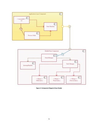
1
Session
Component Diagram
Checklist
 Introduction to Component Diagram
 Elements of Component Diagram
 Construct Component Diagram for
Case Study
2
Component Diagram
Physical implementation of a system should address three primarily problems, they are
Software, Hardware and the interaction between them. Component Diagram are used to
represent physical implementation of the software design whereas physical architecture of the
system is represented using deployment diagrams. Combine them both you can see your
application software running across your hardware. Session 7 details about Deployment
Diagrams.
Consider each component as a bunch of code running on a physical piece of hardware. Each
component should provide interfaces to be serviced by other components of the software
design. The logical implementation are done by the classes that are encapsulated within the
component.
Components can be grouped into three categories
 Deployment Components – Components which are required to run a system
 Work product Components – Components which produce Deployment components
 Execution Components – Components created while running the application.
Elements of Component diagrams?
Elements of component diagram are not much different than what we have seen in class
diagram and composite structure diagram. UML 2 has a notation to represent component
diagram as shown in the figure below. Just Add () to a class or <<component>> stereotype to a
class.
3
Figure 1: Component Notation
Component Stereotype
Components stereotype provides visual cues about roles played by components in a system.
Some of component stereotype are as follows.
Figure 2: Component Stereotype
Constructing Component Diagram for our Case Study
Problem Statement
We are going to use Coffee Vending Machine for our case study. This is the coffee machine that
are used in coffee shops that are operated by store’s worker. Operator can select the type of
coffee and our system provides one by mixing correct portions of milk, water and flavor.
Operator can cancel the order at any time and the system would stop preparing coffee. Our
system gives status information to the operator too. Figure below shows the component
diagram of Coffee Vending Machine.
4
Solution
Our system has two layers; Application Layer and Middleware Layer. Let us look at the
components and the functionality they provide for the system.
Table 1: Component Diagram Functionalities
Components Functionality
Application Layer
UI Handles what to be displayed on the screen. It is an executable. It requires
services from Process Order and State Machine to update the display
accordingly
Process Order Core functionality of coffee making part is handled here. It is an
executable. It updates the state machine and talks with lower layers of the
system to prepare coffee.
State Machine Maintains the state of the system. Gets input from status manager for
status change events from hardware or from the operator
Middleware Layer
Status Manager Status Manager uses IPC mechanism and stands a medium of
communication between Application layer and Middleware layer. It
interacts with Interrupt Handler and Tank Manager.
Interrupt Handler Handles external interrupts to the system. For Example when system losses
it power or when the operator cancels the order. When such events occur
Interrupt Handler informs the status manager so that application layer
components knows about the event.
Tank Manager It communicates with library files to update the status manager about our
Vending machines tank status.
For Example: If Water tank is empty WaterTank.a presents event
notification to TankManager. TankManager then validates the event and
updates the StatusManager
5
Figure 3: Component Diagram (Case Study)
6
Review
 Component Diagram is used to represent physical implementation
of a software design
 Components can be grouped as Deployment Component, Work
Product Component and Execution Component
 Component states provide visual cue to the function of the component

Component Diagram

  • 1.
    1 Session Component Diagram Checklist  Introductionto Component Diagram  Elements of Component Diagram  Construct Component Diagram for Case Study
  • 2.
    2 Component Diagram Physical implementationof a system should address three primarily problems, they are Software, Hardware and the interaction between them. Component Diagram are used to represent physical implementation of the software design whereas physical architecture of the system is represented using deployment diagrams. Combine them both you can see your application software running across your hardware. Session 7 details about Deployment Diagrams. Consider each component as a bunch of code running on a physical piece of hardware. Each component should provide interfaces to be serviced by other components of the software design. The logical implementation are done by the classes that are encapsulated within the component. Components can be grouped into three categories  Deployment Components – Components which are required to run a system  Work product Components – Components which produce Deployment components  Execution Components – Components created while running the application. Elements of Component diagrams? Elements of component diagram are not much different than what we have seen in class diagram and composite structure diagram. UML 2 has a notation to represent component diagram as shown in the figure below. Just Add () to a class or <<component>> stereotype to a class.
  • 3.
    3 Figure 1: ComponentNotation Component Stereotype Components stereotype provides visual cues about roles played by components in a system. Some of component stereotype are as follows. Figure 2: Component Stereotype Constructing Component Diagram for our Case Study Problem Statement We are going to use Coffee Vending Machine for our case study. This is the coffee machine that are used in coffee shops that are operated by store’s worker. Operator can select the type of coffee and our system provides one by mixing correct portions of milk, water and flavor. Operator can cancel the order at any time and the system would stop preparing coffee. Our system gives status information to the operator too. Figure below shows the component diagram of Coffee Vending Machine.
  • 4.
    4 Solution Our system hastwo layers; Application Layer and Middleware Layer. Let us look at the components and the functionality they provide for the system. Table 1: Component Diagram Functionalities Components Functionality Application Layer UI Handles what to be displayed on the screen. It is an executable. It requires services from Process Order and State Machine to update the display accordingly Process Order Core functionality of coffee making part is handled here. It is an executable. It updates the state machine and talks with lower layers of the system to prepare coffee. State Machine Maintains the state of the system. Gets input from status manager for status change events from hardware or from the operator Middleware Layer Status Manager Status Manager uses IPC mechanism and stands a medium of communication between Application layer and Middleware layer. It interacts with Interrupt Handler and Tank Manager. Interrupt Handler Handles external interrupts to the system. For Example when system losses it power or when the operator cancels the order. When such events occur Interrupt Handler informs the status manager so that application layer components knows about the event. Tank Manager It communicates with library files to update the status manager about our Vending machines tank status. For Example: If Water tank is empty WaterTank.a presents event notification to TankManager. TankManager then validates the event and updates the StatusManager
  • 5.
    5 Figure 3: ComponentDiagram (Case Study)
  • 6.
    6 Review  Component Diagramis used to represent physical implementation of a software design  Components can be grouped as Deployment Component, Work Product Component and Execution Component  Component states provide visual cue to the function of the component