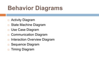
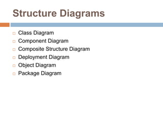
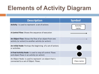
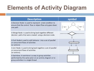
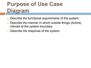
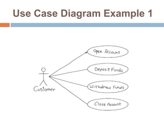
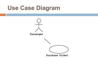
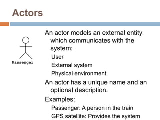
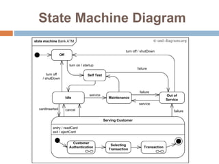
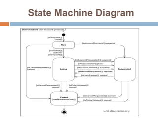
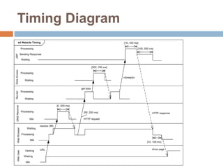
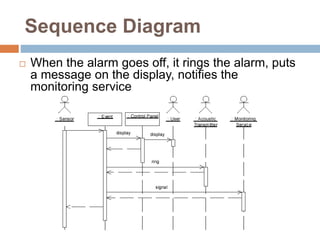
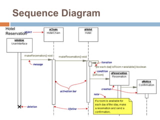
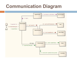
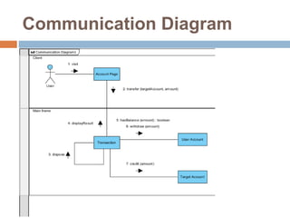
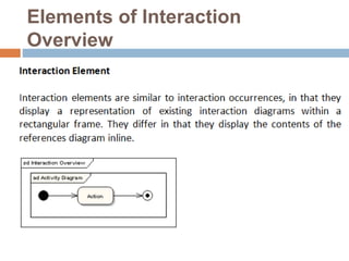
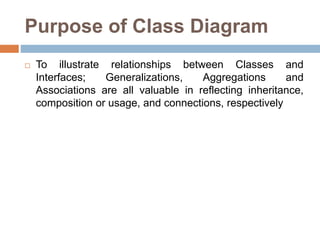
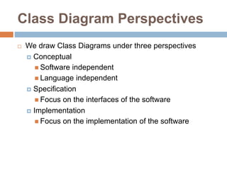
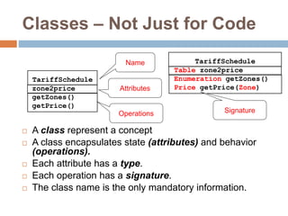
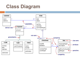
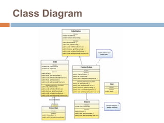
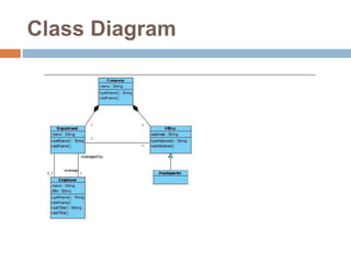
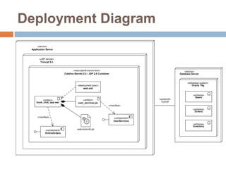
UML & ENTERPRISE
ARCHITECT
Md. Touhidul Alam
Sr. Software Engineer – II
BRAC ICT
Behavior Diagrams
 Activity Diagram
 State Machine Diagram
 Use Case Diagram
 Communication Diagram
 Interaction Overview Diagram
 Sequence Diagram
 Timing Diagram
Structure Diagrams
 Class Diagram
 Component Diagram
 Composite Structure Diagram
 Deployment Diagram
 Object Diagram
 Package Diagram
Elements of Activity Diagram
Purpose of Use Case
Diagram
 Describe the functional requirements of the system
 Describe the manner in which outside things (Actors)
interact at the system boundary
 Describe the response of the system.
Use Case Diagram Example 1
Use Case Diagram
Passenger
Purchase Ticket
Actors
An actor models an external entity
which communicates with the
system:
User
External system
Physical environment
An actor has a unique name and an
optional description.
Examples:
Passenger: A person in the train
GPS satellite: Provides the system
Passenger
Use Case
A use case represents a class of
functionality provided by the system
as an event flow.
A use case consists of:
Unique name
Participating actors
Entry conditions
Flow of events
Exit conditions
Special requirements
PurchaseTicket
Advantages of Use Case
 Determining requirements
 New use cases often generate new requirements as the
system is analyzed and the design takes shape.
 Communicating with clients
 Their notational simplicity makes use case diagrams a
good way for developers to communicate with clients.
 Generating test cases
 The collection of scenarios for a use case may suggest a
suite of test cases for those scenarios.
Protocol State Machine Diagram
 Protocol state machine diagrams are used to express a
usage protocol or a lifecycle of some classifier. It shows
which operations of the classifier may be called in each
state of the classifier, under which specific conditions,
and satisfying some optional post-conditions after the
classifier transitions to a target state.
 The notation for protocol state machine is similar to the
one of behavioral state machines. The
keyword {protocol} is placed close to the name of the
state machine to differentiate protocol state machine
diagrams.
Purpose of State Machine
Diagram
 Create a state machine diagram to
 explore the complex behavior of a class, actor,
subsystem, or component;
 model real-time systems.
State Machine Diagram
Elements
State Machine Diagram
Elements
State Machine Diagram
Elements
State Machine Diagram
Elements
State Machine Diagram
Elements
State Machine Diagram
Elements
State Machine Diagram
Elements
State Machine Diagram
Elements
State Machine Diagram
Elements
State Machine Diagram
Elements
State Machine Diagram
Elements
State Machine Diagram
Elements
Timing Diagrams
 Timing diagrams are interaction diagrams used to show
interactions when a primary purpose of the diagram is to
reason about time.
 Timing diagrams focus on conditions changing within
and among lifelines along a linear time axis.
 Timing diagrams describe behavior of both
individual classifiers and interactions of classifiers,
focusing attention on time of events causing changes in
the modeled conditions of the lifelines.
Purpose of Timing Diagram
 Timing diagrams are often used in the design of
embedded software, such as control software for a fuel
injection system in an automobile, although they
occasionally have their uses for business software too.
 Timing diagram should be created when timing, not
sequence, is of critical importance.
Timing Diagram
Sequence Diagram
 When the alarm goes off, it rings the alarm, puts
a message on the display, notifies the
monitoring service
Sequence Diagram
Hotel
Reservation
Communication Diagram
Elements of Interaction
Overview
Structural Diagrams
 Class Diagram
 Component Diagram
 Composite Structure Diagram
 Deployment Diagram
 Object Diagram
 Package Diagram
Purpose of Class Diagram
 To illustrate relationships between Classes and
Interfaces; Generalizations, Aggregations and
Associations are all valuable in reflecting inheritance,
composition or usage, and connections, respectively
Class Diagram Perspectives
 We draw Class Diagrams under three perspectives
 Conceptual
 Software independent
 Language independent
 Specification
 Focus on the interfaces of the software
 Implementation
 Focus on the implementation of the software
Classes – Not Just for Code
 A class represent a concept
 A class encapsulates state (attributes) and behavior
(operations).
 Each attribute has a type.
 Each operation has a signature.
 The class name is the only mandatory information.
zone2price
getZones()
getPrice()
TariffSchedule
Table zone2price
Enumeration getZones()
Price getPrice(Zone)
TariffScheduleName
Attributes
Operations Signature
Class Diagram
Class Diagram
Class Diagram
Purpose of Composite Structure
Diagram
 To depict the internal structure of a classifier (such as a
class, component, or use case), including the interaction
points of the classifier to other parts of the system.
 To explore how a collection of cooperating instances
achieves a specific task or set of tasks.
 To describe a design or architectural pattern or strategy.
Composite Structure Diagram
Object Diagram
Object Diagram
Deployment Diagram
THANK YOU
Md. Touhidul Alam
Sr. Software Engineer – II
engr.shuvo@yahoo.com

Uml and enterprise architect