Downloaded 48 times
![3
Link
Objects are connected with links (a line) that has names and no multiplicity. All links are one to
one and roles can be attached to links. In the below example OrderId_5 is an instance of Order
class and has produced two products [anonymous object & Vendor_Id_112]. Customer and
Vendor are role names that are denoted on the links.
Figure 2: Link Notation
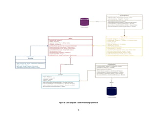
Testing Order processing system with Object diagram
Let us consider our last constructed class diagram and test the object of Order.
Figure 3: Object Diagram - Order Processing System v0.1](https://image.slidesharecdn.com/article4objectdiagram-150606054435-lva1-app6892/85/Object-diagram-3-320.jpg)


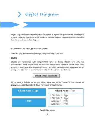
The document provides a checklist for understanding and constructing object diagrams, highlighting their role as snapshots of system objects at a specific time. It explains the elements of object diagrams, which consist of objects and links, and discusses testing an order processing system using these diagrams to identify flaws in the class diagram. Corrections to the identified errors are presented alongside an updated version of the class diagram.


![[RPL2] Pertemuan 3 - UML dan USECASE VIEW](https://cdn.slidesharecdn.com/ss_thumbnails/rpl2pertemuan3-umldanusecaseview-181013010605-thumbnail.jpg?width=640&height=640&fit=bounds)


![Ch.03 - Class Diagram_1 OBJECT ORIENTED ANALYSIS AND DESIGN [O] .pptx](https://cdn.slidesharecdn.com/ss_thumbnails/ch-240306182454-90ef2421-thumbnail.jpg?width=640&height=640&fit=bounds)


![Lect 1 Number systems and base conversions. [Autosaved].pptx](https://cdn.slidesharecdn.com/ss_thumbnails/lect1numbersystemsandbaseconversions-260111134109-67c2d865-thumbnail.jpg?width=640&height=640&fit=bounds)


