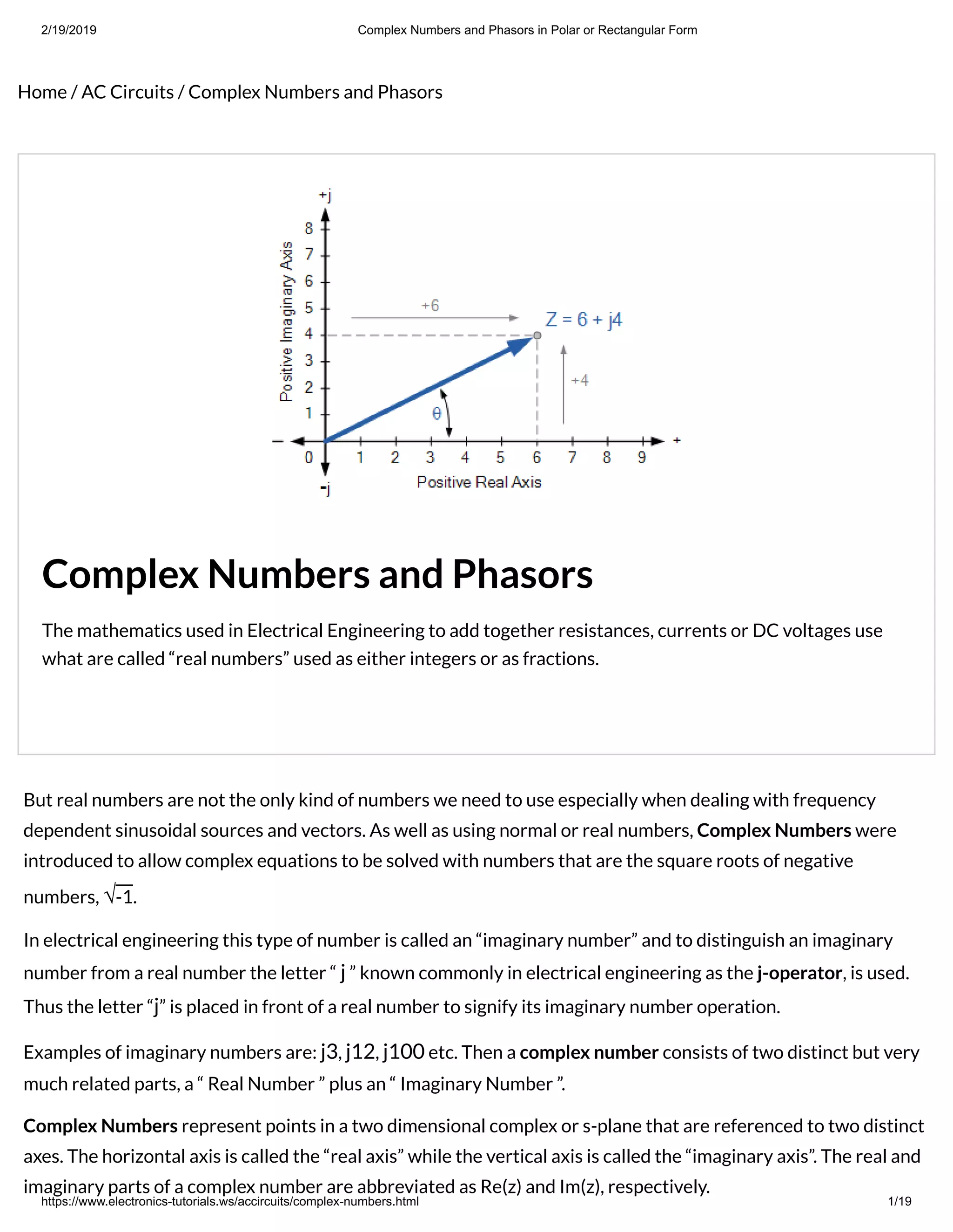
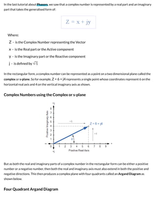
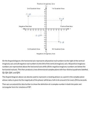
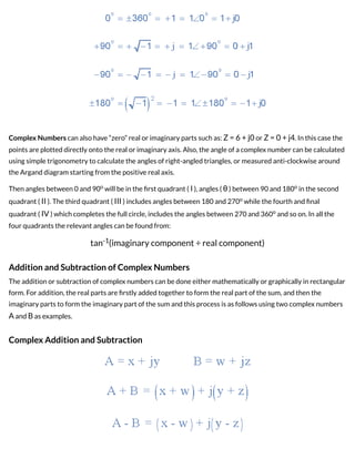
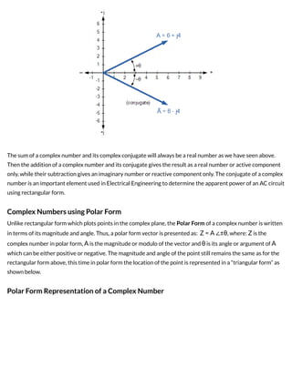
1) Complex numbers consist of real and imaginary parts and are represented as points on an Argand diagram with real numbers on the horizontal axis and imaginary numbers on the vertical axis.
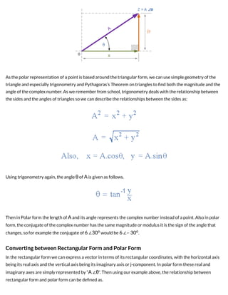
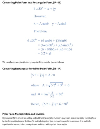
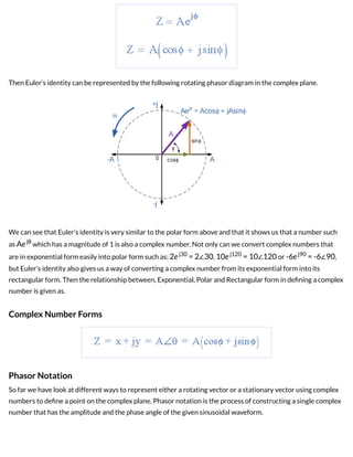
2) There are two main ways to represent complex numbers - rectangular form uses the real and imaginary parts, while polar form specifies the magnitude and angle of the complex number.
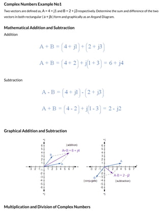
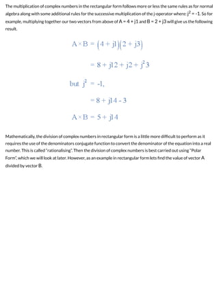
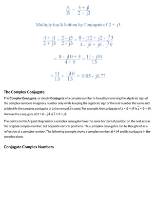
3) Operations like addition, subtraction, multiplication and division can be performed on complex numbers by following rules for manipulating the real and imaginary parts or converting between rectangular and polar form. Complex conjugates are used in some operations like division of complex numbers.