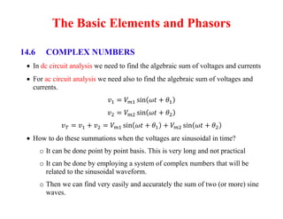
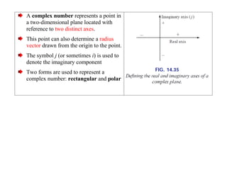
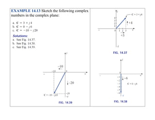
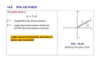
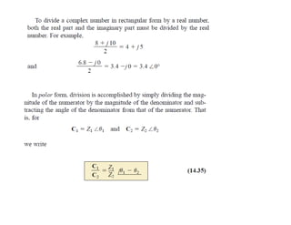
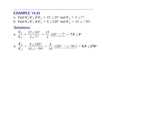
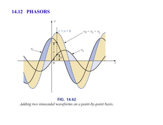
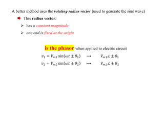
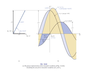
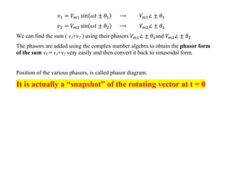
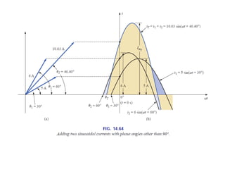
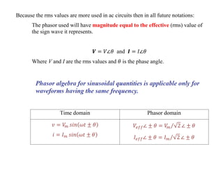
The Basic Elements and Phasors
14.6 COMPLEX NUMBERS
 In dc circuit analysis we need to find the algebraic sum of voltages and currents
 For ac circuit analysis we need also to find the algebraic sum of voltages and
currents.
 How to do these summations when the voltages are sinusoidal in time?
o It can be done point by point basis. This is very long and not practical
o It can be done by employing a system of complex numbers that will be
related to the sinusoidal waveform.
o Then we can find very easily and accurately the sum of two (or more) sine
waves.
A complex number represents a point in
a two-dimensional plane located with
reference to two distinct axes.
This point can also determine a radius
vector drawn from the origin to the point.
The symbol j (or sometimes i) is used to
denote the imaginary component
Two forms are used to represent a
complex number: rectangular and polar
14.7 RECTANGULAR FORM
The rectangular form is:
Boldface ≡ vector (magnitude and
direction)
Italic ≡ magnitude only
EXAMPLE 14.13 Sketch the following complex
numbers in the complex plane:
14.8 POLAR FORM
The polar form is:
Z ≡ magnitude only always positive
≡ angle measured counter-clockwise
(CCW) from the positive real axis
Angle measured clockwise must have a
minus sign associated
EXAMPLE 14.14 Sketch the following
complex numbers in the complex plane:
14.9 CONVERSION BETWEEN FORMS
14.10 MATHEMATICAL OPERATIONS WITH COMPLEX
NUMBERS
Complex Conjugate
The conjugate or complex conjugate of a complex number can be found by simply
changing the sign of the imaginary part in the rectangular form or by using the
negative of the angle of the polar form:
The conjugate of:
is
The conjugate of:
is
14.12 PHASORS
A better method uses the rotating radius vector (used to generate the sine wave)
This radius vector:
 has a constant magnitude
 one end is fixed at the origin
is the phasor when applied to electric circuit
We can find the sum ( v1+v2 ) using their phasors and
The phasors are added using the complex number algebra to obtain the phasor form
of the sum vT = v1+v2 very easily and then convert it back to sinusoidal form.
Position of the various phasors, is called phasor diagram.
It is actually a “snapshot” of the rotating vector at t = 0
Because the rms values are more used in ac circuits then in all future notations:
The phasor used will have magnitude equal to the effective (rms) value of
the sign wave it represents.
and
Where V and I are the rms values and is the phase angle.
Time domain Phasor domain
slides_12_ch 14-2- complex numbers.pdf

slides_12_ch 14-2- complex numbers.pdf

  • 1.
    The Basic Elementsand Phasors 14.6 COMPLEX NUMBERS  In dc circuit analysis we need to find the algebraic sum of voltages and currents  For ac circuit analysis we need also to find the algebraic sum of voltages and currents.  How to do these summations when the voltages are sinusoidal in time? o It can be done point by point basis. This is very long and not practical o It can be done by employing a system of complex numbers that will be related to the sinusoidal waveform. o Then we can find very easily and accurately the sum of two (or more) sine waves.
  • 2.
    A complex numberrepresents a point in a two-dimensional plane located with reference to two distinct axes. This point can also determine a radius vector drawn from the origin to the point. The symbol j (or sometimes i) is used to denote the imaginary component Two forms are used to represent a complex number: rectangular and polar
  • 3.
    14.7 RECTANGULAR FORM Therectangular form is: Boldface ≡ vector (magnitude and direction) Italic ≡ magnitude only
  • 4.
    EXAMPLE 14.13 Sketchthe following complex numbers in the complex plane:
  • 5.
    14.8 POLAR FORM Thepolar form is: Z ≡ magnitude only always positive ≡ angle measured counter-clockwise (CCW) from the positive real axis Angle measured clockwise must have a minus sign associated
  • 7.
    EXAMPLE 14.14 Sketchthe following complex numbers in the complex plane:
  • 8.
  • 11.
    14.10 MATHEMATICAL OPERATIONSWITH COMPLEX NUMBERS
  • 12.
    Complex Conjugate The conjugateor complex conjugate of a complex number can be found by simply changing the sign of the imaginary part in the rectangular form or by using the negative of the angle of the polar form: The conjugate of: is
  • 13.
  • 28.
  • 29.
    A better methoduses the rotating radius vector (used to generate the sine wave) This radius vector:  has a constant magnitude  one end is fixed at the origin is the phasor when applied to electric circuit
  • 31.
    We can findthe sum ( v1+v2 ) using their phasors and The phasors are added using the complex number algebra to obtain the phasor form of the sum vT = v1+v2 very easily and then convert it back to sinusoidal form. Position of the various phasors, is called phasor diagram. It is actually a “snapshot” of the rotating vector at t = 0
  • 33.
    Because the rmsvalues are more used in ac circuits then in all future notations: The phasor used will have magnitude equal to the effective (rms) value of the sign wave it represents. and Where V and I are the rms values and is the phase angle. Time domain Phasor domain