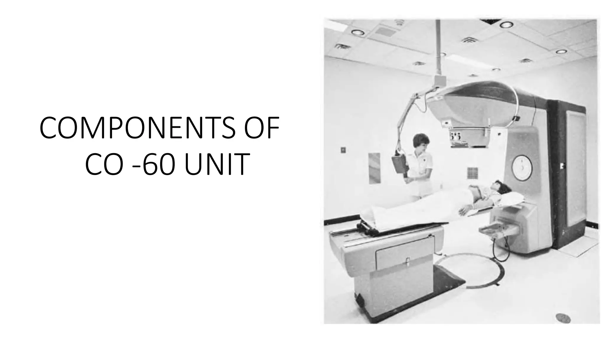
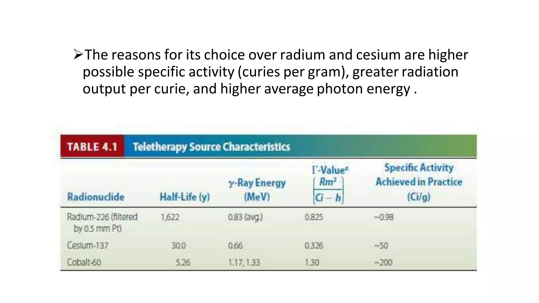
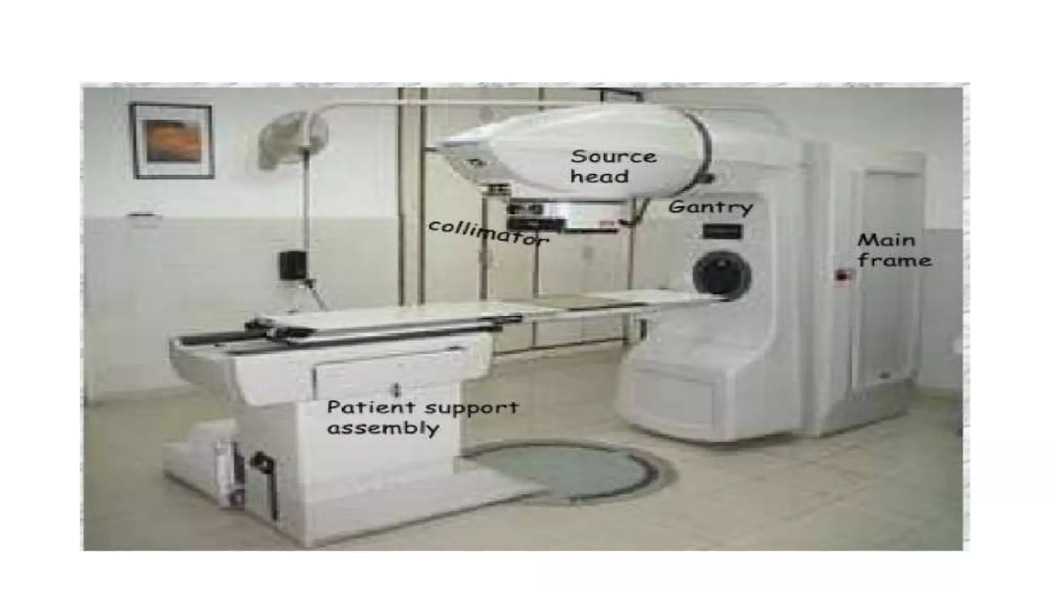
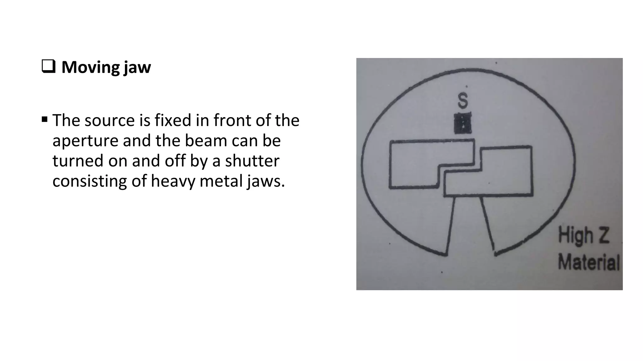
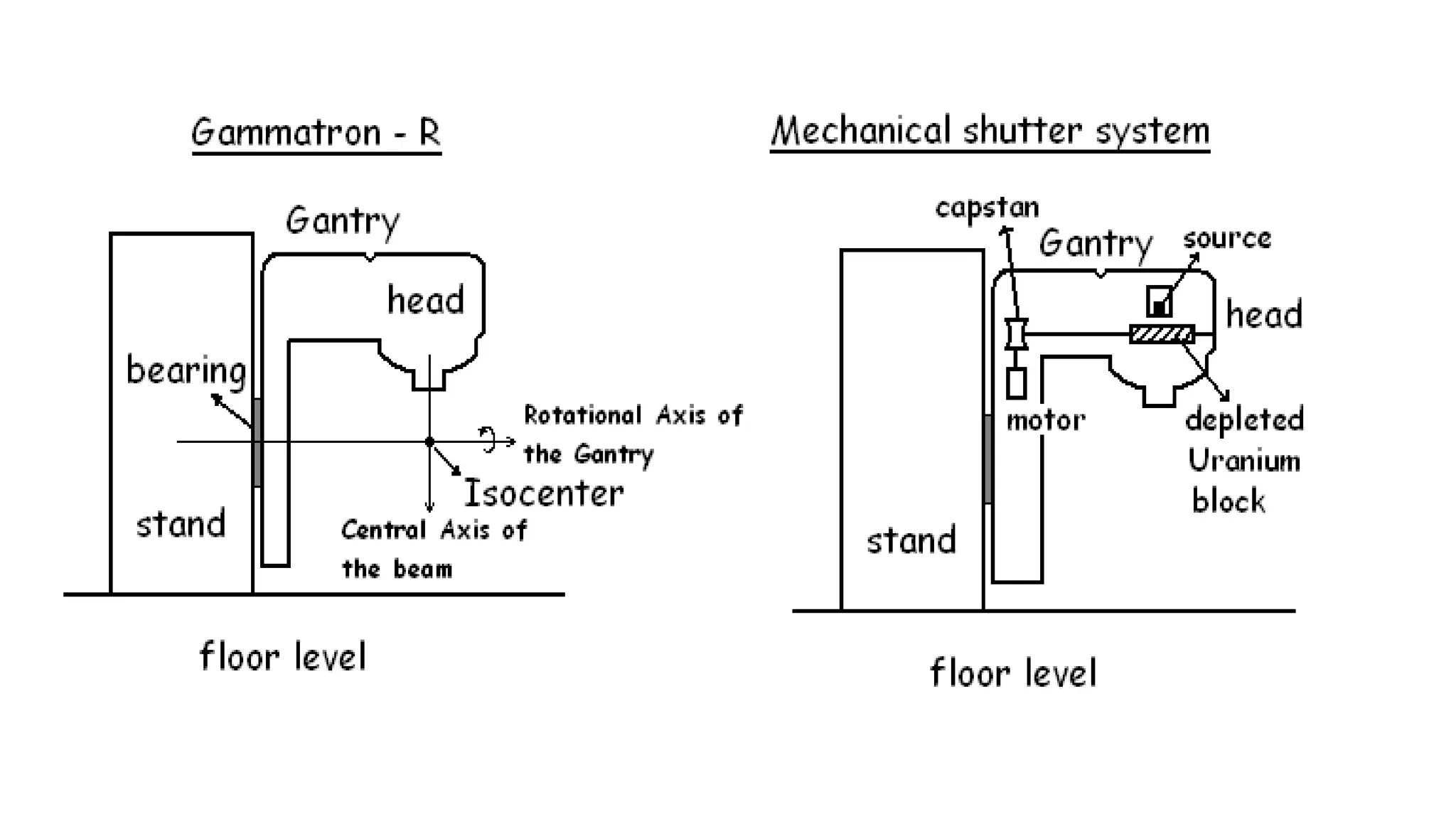
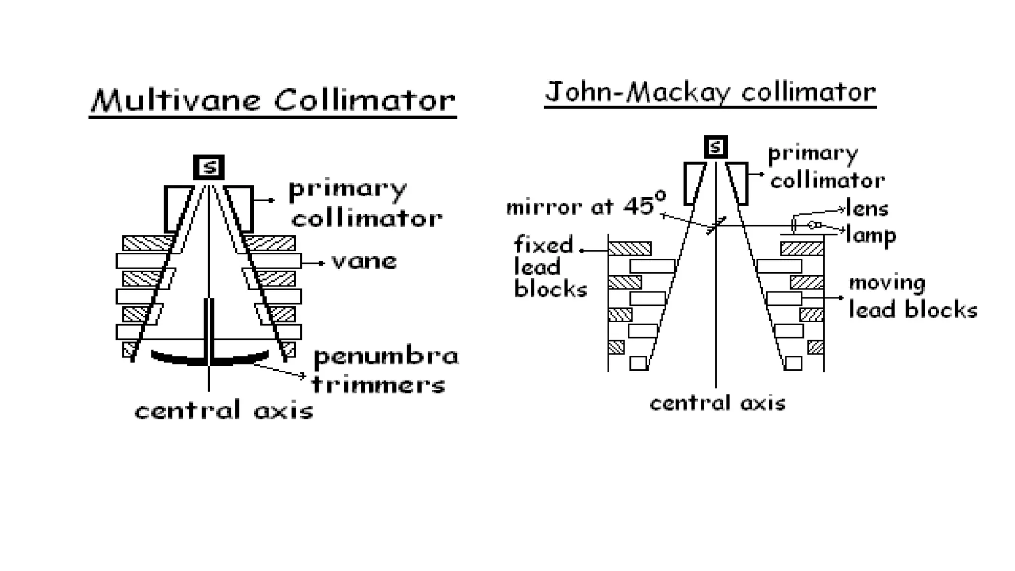
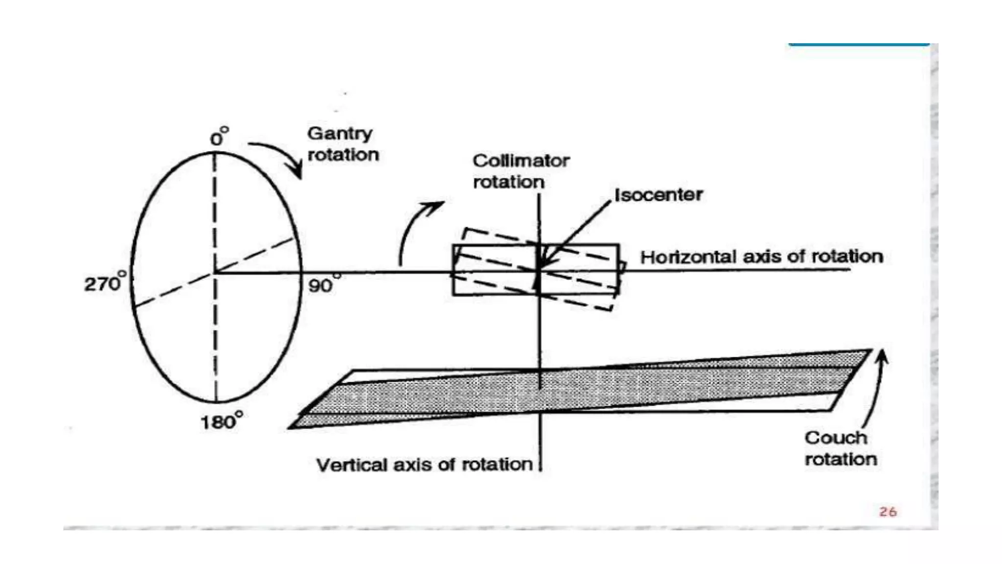
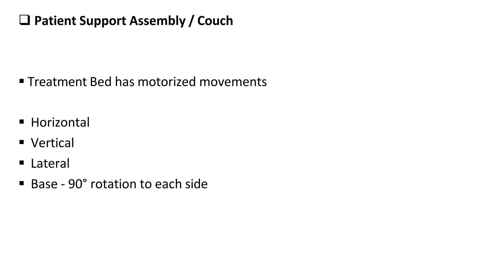
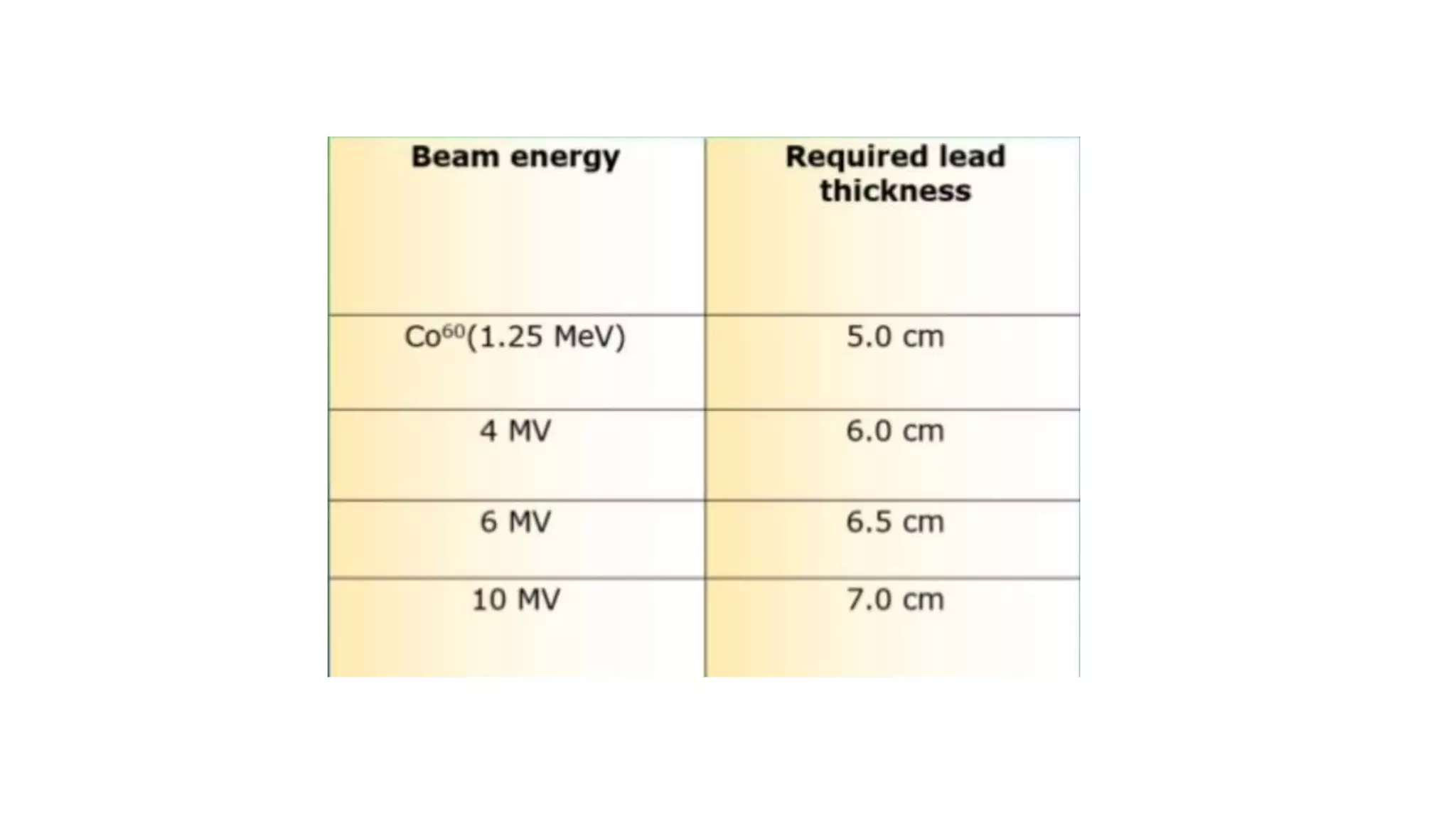
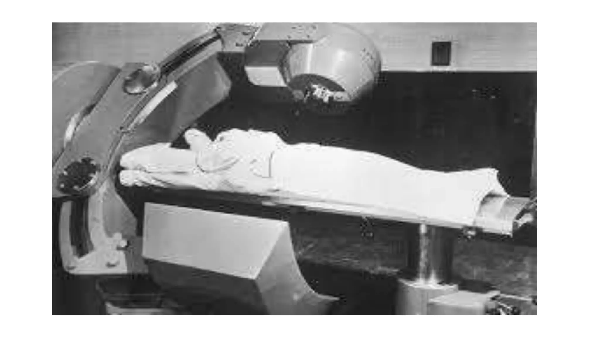
2. • Overview:
Radionuclide's such as cesium-137, and cobalt-60 have been used as
sources of gamma rays for teletherapy.
These gamma rays are emitted from the radionuclide's as they undergo
radioactive disintegration.
Of all the radionuclide's, Co-60 has proved to be the most suitable for
external beam radiotherapy.
A typical source activities are in the order of 5000-10,000 ci and provide
typical dose rate at 80 cm from the teletherapy source of the order of
100- 200 cGy/min.
3. The reasons for its choice over radium and cesium are higher
possible specific activity (curies per gram), greater radiation
output per curie, and higher average photon energy .
4.
5. COBALT-60 UNIT:
Source
The 60Co source, usually in the form of a solid cylinder, disks, or pallets,
is contained inside a stainless-steel capsule and sealed by welding.
This capsule is placed into another steel capsule which is again sealed by
welding.
The double-welded seal is necessary to prevent any leakage of the
radioactive material.
A typical teletherapy 60Co source is a cylinder of diameter ranging
from 1.5 to 2.0 cm and is positioned in the cobalt unit with its
circular end facing the patient.
6. The Co-60 source decays to Ni-60 with the emission of β particles (Emax = 0.32
MeV) and two photons per disintegration of energies 1.17 and 1.33 MeV.
These gamma rays constitute the useful treatment beam.
The β particles are absorbed in the cobalt metal and the stainless-steel
capsules resulting in the emission of bremsstrahlung x-rays and a small amount
of characteristic x-rays – 0.1Mev
25% of the primary photons are lost because of the self attenuation of
the source.
7.
8. Source Housing / source head
Functions of the head:
• To shield the source
• To expose the source as required
• To collimate the beam to correct size
9. Source Housing / source head
It consists of a steel shell filled with lead for shielding purposes and a device
for bringing the source in front of an opening in the head from which the
useful beam emerges.
a heavy metal alloy sleeve is provided to form an additional primary shield
when the source is in the off position.
A number of methods have been developed for moving the source
from the off position to the on position, which are as follows:
11. Sliding drawer
A pneumatically driven source
drawer is used for moving the
source between shielded
position and treatment position.
The pneumatic cylinder will
return the source
automatically to radiation-off
position in case of any failure.
12.
13. Rotating wheel
The source mounted on a
rotating wheel inside the
sourcehead to carry the source
from the off position to the on
position.
14.
15. Mercury shutter
mercury is allowed to flow into
the space immediately below
the source to shut off the beam.
16.
17. Moving jaw
The source is fixed in front of the
aperture and the beam can be
turned on and off by a shutter
consisting of heavy metal jaws.
18.
19. Beam Collimation
The size and orientation of the radiation beam is controlled by the collimator
assembly.
Two pairs of motorized jaws generate rectangular and square field of desired
size.
The collimator can also be rotated around the radiation beam axis.
The radiation field can be visualized by a high intensity light during patient
positioning.
Multivane collimators are used as secondary collimators.
20.
21. The centre of the radiation field
is indicated by the collimator
cross hairs.
Two sets of trimmers are
provided to decrease the
penumbra of the beam.
The lower pad of the collimator
is prepared to receive wedge
filters and shadow tray for the
beam shaping lead blocks.
22. Penumbra
Penumbra refers the region at the edge of beam where dose rate changes
rapidly as function of distance from beam axis.
Types of penumbra :
Geometric
Transmission
For 1.5mm source diameter, penumbra will be <10mm at 5cm depth for
field area <400cm^2.
23. Transmission penumbra
• It is the region irradiated by photons which are transmitted through the
edge of the collimator blocks
Geometrical penumbra :
formula =
• it is formed due to dimension of source.
• It is formed due to finite source size and must be concern in teletherapy
machines where the sources is between 1 – 2 cm in size.
24.
25. Conclusions :
penumbra increases with increase in source diameter , SSD , and depth.
Penumbra width decreases with a increase in SDD
penumbra trimmers - :
it consists of extensible , heavy metal bars to attenuate the beam in the
penumbra region.
increase the source to diaphragm distance , reducing the geometric
penumbra.
26. Gantry
The gantry can rotate by 360°. The rotational movement of the gantry is
motorized and controlled in two directions continuously; its rotation speed
can be adjusted.
Teletherapy machines are most often mounted isocentrically, allowing the
beam to rotate about the patient at a fixed SAD. They can be used either as
fixed field machines or rotation units.
Most cobalt-60 unit machines have SAD of 80 cm.
27. The axis of rotation of the three structures:
Gantry
Collimator
Couch
coincide at a point known as the Isocenter.
Isocentric Mounting
Enhances accuracy.
Allows faster setup and is more accurate than older non isocentrically
mounted machines.
Makes setup transfer easy from the simulator to the treatment machine
28.
29. Patient Support Assembly / Couch
Treatment Bed has motorized movements
Horizontal
Vertical
Lateral
Base - 90° rotation to each side
30. Control Console
Control Console is situated outside the bunker
Interlocks present on the console for- :
Air Pressure
Door
Head Lock -Treatment Head has a swivel movement of +/- 180°.
OFF Shield
Treatment Mode.
Wedge Filter.
Tray Interlock.
Timer
31. Warning lights
• Red light: Radiation present- do not enter room
• Green Light: treatment time elapsed-safe
• Yellow light: during the treatment
• Malfunction: both red and green lights still on- means that machine is still
in on position after prescribed dose has been delivered. Remove patient.
32. Beam shaping and modifying devices
The system has accessories like -:
wedge filters
Breast cone
Sheilding blocks, to modify the beam shape or beam attenuation.
They are placed on the machine between the collimator and the patient.
33. wedge filters
special filters or absorbing blocks are placed in the path of a beam to
modify its isodose distribution.
The most commonly used beam-modifying device is the wedge filter.
This is a wedge-shaped absorber that causes a progressive decrease in the
intensity across the beam, resulting in a tilt of the isodose curves from their
normal positions.
34. the isodose curves are tilted
toward the thin end, and the
degree of tilt depends on the slope
of the wedge filter.
In actual wedge filter design, the
sloping surface is made either
straight or sigmoid in shape .
35. The wedge is usually made of a dense material, such as lead or steel, and
is mounted on a transparent plastic tray,
which can be inserted in the beam at a specified distance from the source .
This distance is arranged such that the wedge tray is always at a distance of at
least 15 cm from the skin surface,
so as to avoid destroying the skin-sparing effect of the megavoltage beam.
36. SHIELDING BLOCKS
Aims of shielding-
protect critical structures ( organ )
avoid unnecessary radiation to normal tissues
matching adjacent fields
37. An ideal shielding material should have the following characteristics :
high atomic no
high density
easily available
inexpensive
easily modifiable
The most commonly used shielding material for photons is Lead ( Pb )
The thickness of shielding block used depends upon the energy of the
radiation
38. The shielding material which reduces beam transmission to 5% of its original is
considered acceptable .
The term half value layer is an expression for the attenuation produced by any
material.
half-value layer (HVL) is defined as the thickness of an absorber of specified
composition required to attenuate the intensity of the beam to half its original
value.
Practically thickness of lead between 4.5 – 5 half value layers which results in
5% or less of primary beam transmission.
39. Custom blocks
• The conformal blocks are made with low melting point alloy called Cerrobend.
• The Cerrobend material consists of 50.0% bismuth, 26.7% lead, 13.3% tin, and 10.0%
cadmium .
• The main advantage of Cerrobend over lead is that it melts at about 70 °C (compared with
327 °C for lead) and therefore, can be easily cast into any shape.
• At room temperature, it is harder than lead.
• The minimum thickness of Cerrobend blocks required for blocking may be calculated from
Table 13.1 using its density ratio relative to lead (e.g., multiply lead thickness by 1.21).
40.
41. T - ROD mechanism in cobalt-60 unit
The external T-ROD shall be fitted with this indicator rod incase of failure of
Automatic source retracting system to push the source to the OFF condition.
Source stuck during treatment – Emergency situation when the Cobalt-60
source gets stuck in between the “off” and “on” position .
Rotate gantry to side opposite to maze wall – Insert “T-rod” and push it till the
source reaches “safe” position
42.
43. The beamstopper
The beamstopper is a lead-filled steel assembly, which acts as a beam
absorber. The beamstopper attenuates 99.9% of the primary beam.
A beam stopper is used to intercept the beam for additional shielding of the
exit beam. The beam stop also acts as a counterweight for the head of the
machine.