This document discusses 2.5D axis and virtual CNC software. It provides examples of commonly used 2.5D axis software like Solidcam, Cambam, and Hypermill, which allow for simplified 2.5D machining operations like profiling and pocketing. Virtual CNC software like SSCNC and VR CNC Milling enables simulation and testing of CNC programs without physical machining, reducing costs and risks of errors. The advantages of these software include simplified programming and simulation of errors, while disadvantages include high costs and need for training.
![1
1.0 INTRODUCTION
The word “CNC” stands for “Computer Numerical Control“. CNC separates between
a machine that has a “Controller” on it from one that is manually run. CNC software is
designed to read CNC programs and initiate a series of machine commands in sequential
order. As direction sets, CNC programs are written in a sentence-like format and with a
particular language structure. CNC words start with lettered addresses and define variables,
for example, speed and axis motion. At the point when gathered together, they form
commands that are read by the software-based CNC control.
Figure 1 : CNC software use in industry
Software-based CNC controllers may give abilities ranging from simple point-to-
point linear control to highly-complex calculations with multiple axes of control. Specialized
CNC and exclusive computer numerical control software is likewise accessible.
Commonly, CNC software runs on an off-the-shelf PC interfaced to the machine
tool’s servo system. Personal computers with CNC software do not require specific hardware,
for example, programmable logic controllers (PLCs) or movement control cards. The CNC
software performs all of the functions of a hardware-based CNC controller, including the
human-machine interface (HMI) and input/output (I/O) control [1].](https://image.slidesharecdn.com/full-180508133828/75/CNC-2-5D-AXIS-vs-VIRTUAL-CNC-1-2048.jpg)

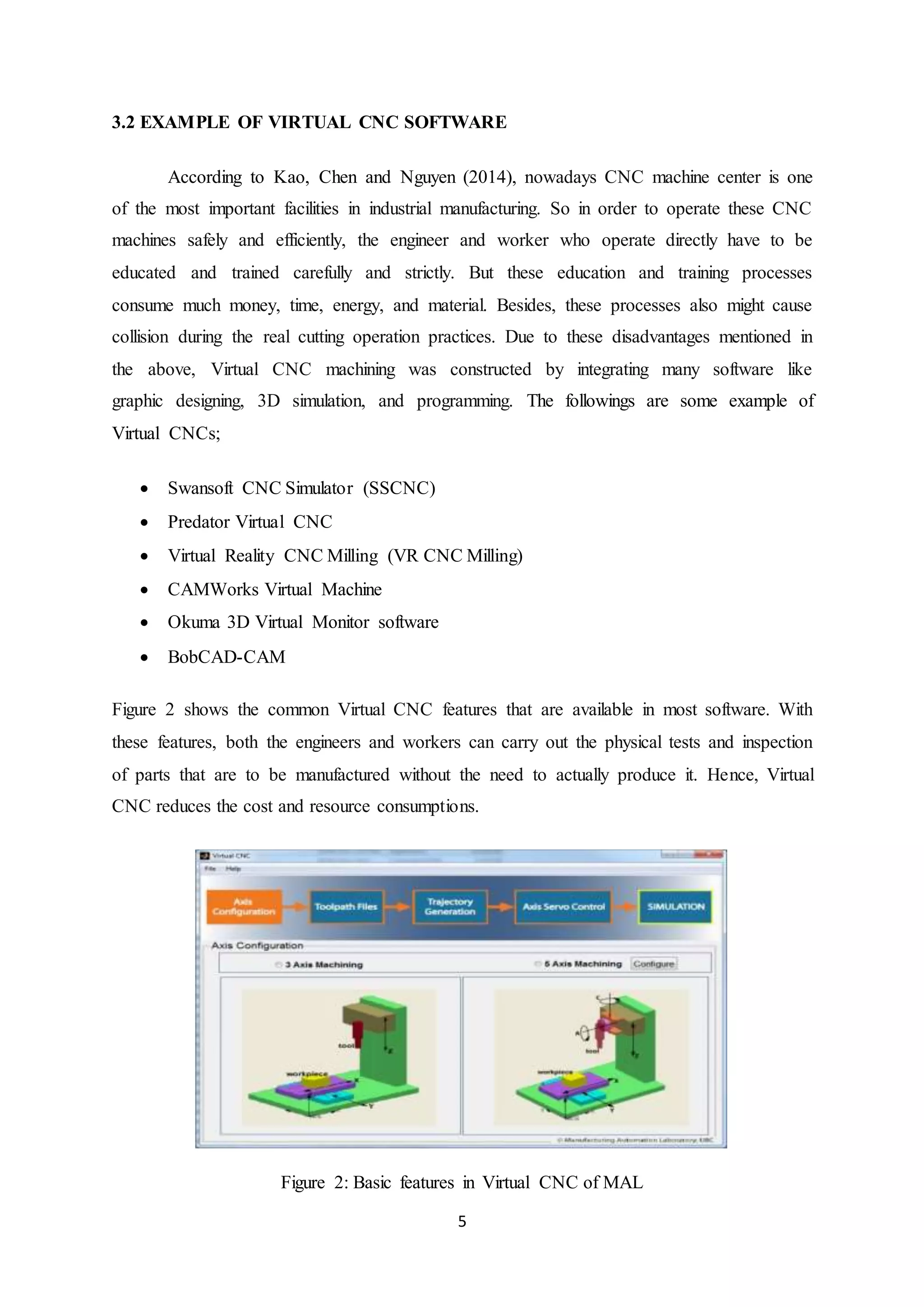
![4
3.0 SOFTWARE
3.1 EXAMPLE OF 2.5D AXIS SOFTWARE
The following is a list of major 2.5D axis software used in industry:
3.1.1 Solidcam
SolidCAM puts the most capable 2.5D programming arrangement at user fingertips, right
inside their CAD system. SolidCAM looks, feels and performs like user existing CAD
system. In addition to its powerful 2.5D milling Profiling, Pocketing and Drilling operations,
SolidCAM's 2.5D module includes Thread Milling operation for machining of standard
internal and external threads and many more [3]
3.1.2 Cambam
CamBam is an application to make CAM files (gcode) from CAD source documents or its
own internal geometry editor. CamBam has many users around the world, from CNC
specialists to professional machinists and engineers.
CamBam currently supports the following:
Reading from and writing to 2D DXF files.
2.5D profiling machine operations with auto-tab support
2.5D pocketing operations with auto island detection
Drilling (Normal,Peck,Spiral Milling and Custom Scripts)
Engraving
3.1.3 Hypermill
According to their official web homepage, HyperMILL is a modular and flexible CAM
solution for 2.5D, 3D and 5-axis milling as well as mill turning and machining operations
such as high-speed cutting (HSC) and high-performance cutting (HPC), with everything
integrated in a single interface. The special applications for milling impellers, blisks, turbine
blades, tubes and tire moulds round off the range of functions available in hyperMILL](https://image.slidesharecdn.com/full-180508133828/75/CNC-2-5D-AXIS-vs-VIRTUAL-CNC-4-2048.jpg)
![8
5.0 SOFTWARE DESCRIPTION
5.1 GIBBSCAM
Figure 3: GibbsCam logo
GibbsCAM is a state-of-the-art, PC-based computer-aided manufacturing (CAM)
system for programming computer numerically controlled (CNC) machine tools. The
company was founded in 1982 by Bill Gibbs. The first release of the program was launched
in 1984 for the Macintosh platform. Since 1996, the software is being developed exclusively
for the Windows platform. The Gibbs CAM program is translated into 20 languages and is
represented in most countries in the world.
GibbsCAM comprises of various basic packages and countless modules. This
enables the user to begin with a simpler CAM program, and then build on more modules as
required. GibbsCAM’s graphical user interface was designed for engineers by engineers,
bringing a user environment that is both familiar and proficient. This manufacturing
orientation guarantees that GibbsCAM’s powerful capabilities is also extremely easy to learn
and use. GibbsCAM’s free-form interaction style enables user to move effectively between
geometry creation, toolpath creation, process visualization/verification and post processing.
GibbsCAM’s ease-of-use, programming productivity, speed and short training time make
GibbsCAM the CAM industry’s ease-of-use leader and the best software for programming
parts [2].](https://image.slidesharecdn.com/full-180508133828/75/CNC-2-5D-AXIS-vs-VIRTUAL-CNC-8-2048.jpg)
![10
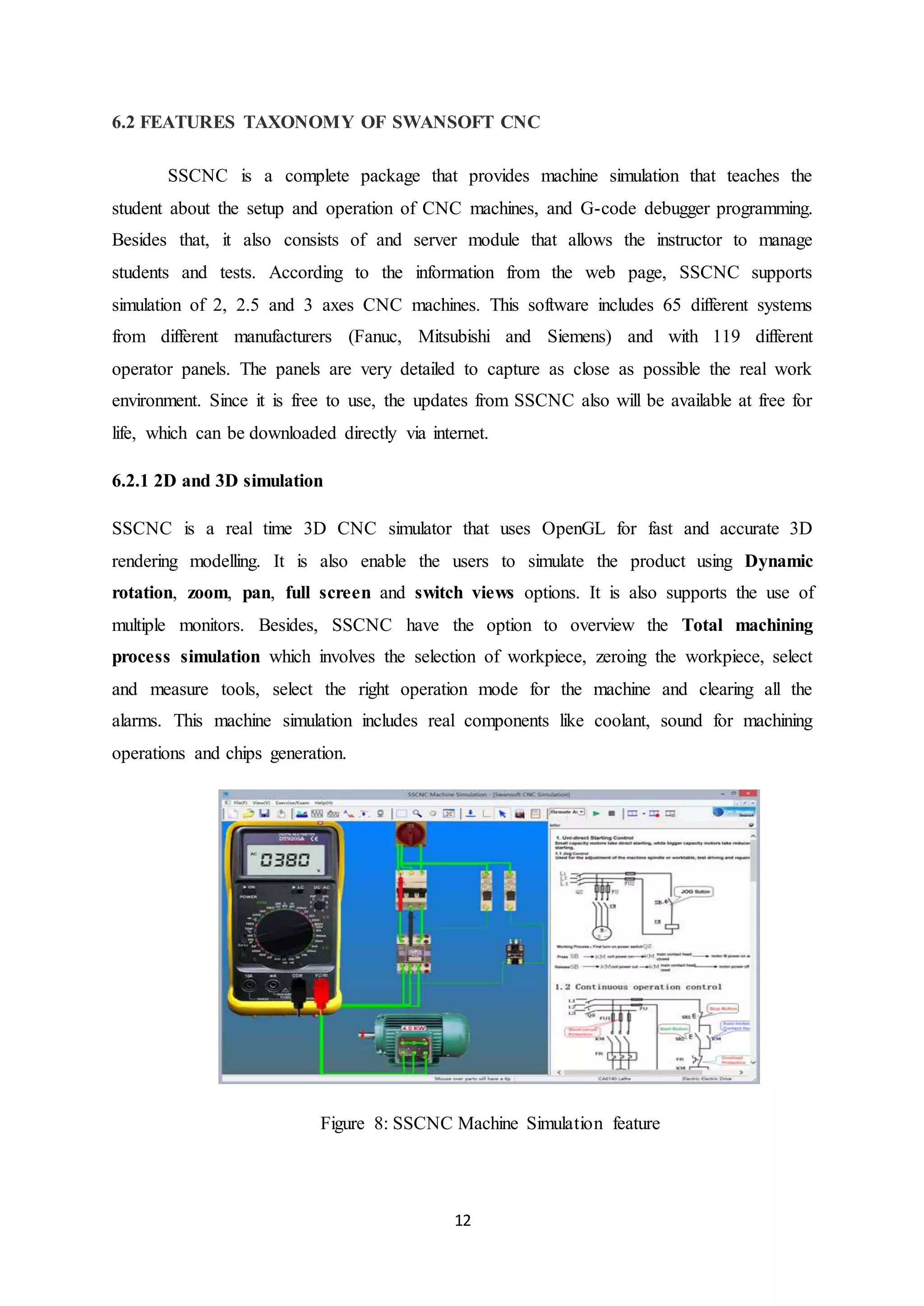
6.0 FEATURES TAXONOMY
6.1 FEATURES TAXONOMY OF GIBBSCAM
The following are the most important features in this software that related to manufacturing
industry:
6.1.1 Production Milling
Supports 2-axis through simple 3-axis wireframe machining with full functionality for face
milling, pocketing with unlimited bosses/islands, contouring, thread milling, 2D/3D spiral
creation, drilling with support for many drill cycles, boring, and tapping. Simple fourth axis
positioning is also supported. Automatic cycles for face milling, for example, zig-zag, spiral,
one direction and back and forth, enable material to be cleaned off the highest point of a
section. GibbsCAM Production Milling provides simple to-utilize, powerful programming
capability for user machine devices.
Figure 5: Production milling using GibbsCam
6.1.2 Production Turning
Supports full 2-axis wireframe machining with full usefulness for tedious shape roughing,
drilling, contouring, automatic roughing, plunge roughing, multiple hills and valleys,
threading, boring and tapping [4]. Advanced functionalities, for example, keeping up an
attention of the current stock condition, make programming lathes easy as well as effective.
GibbsCAM Production Turning provides easy to use software, powerful capability for
programming user turning centers.](https://image.slidesharecdn.com/full-180508133828/75/CNC-2-5D-AXIS-vs-VIRTUAL-CNC-10-2048.jpg)
![11
Figure 6: Production turning using GibbsCam
6.1.3 MTM (Multi-Task Machining)
Specifically designed to address the CNC programming requirements of multi-task machine
devices, giving powerful programming software that are easy to use and learn with the
ultimate in adaptability and configurability. Machining processes are easily defined with
GibbsCAM's intuitive graphical user interface that provides seamless access to both turning
and milling capabilities [4]. GibbsCAM's associativity enables operations to be updated
effectively when changes are made.
Figure 7: Multi-task machine tools](https://image.slidesharecdn.com/full-180508133828/75/CNC-2-5D-AXIS-vs-VIRTUAL-CNC-11-2048.jpg)

![16
8.0 REFERENCES
[1] Engineering 360. (n.d.). Retrieved 10, 10, 2017, from
http://www.globalspec.com/learnmore/industrial_engineering_software/industrial_con
trols_software/computer_numerical_control_software_cnc.
[2] SolidCam. (n.d.). Retrieved 11, 10, 2017, from https://www.solidcam.com/en-us/cam-
solutions/cam-modules/25d-milling/.
[3] Cimatron. (n.d.). Retrieved 14, 10, 2017, from
http://www.cimatron.com/SIP_STORAGE/FILES/7/2647.pdf.
[4] 3Dsystem. (n.d.). Retrieved 18, 10, 2017, from
https://www.3dsystems.com/software/gibbscam/features.
W. Lin & J. Fu. (2006). Modeling and application of virtual machine tool. Proceedings of the
16th international conference on artificial reality and telexistence workshops, ICAT,
9-16.
A.A. Kadir, X. Xu & E. Hämmerle. (2011). Virtual machine tools and virtual machining. A
technological review. Robot Computer Integrated Manufacturing, 27, 494-508.
Y. Yao, H. Zhao, J. Li & Z. Yuan. (2006). Modeling of virtual workpiece with machining
errors representation in turning. Journal of Material Process Technology, 172,
437-444.
Y.C. Kao, M.S. Chen & N.T. Nguyen. (2014). Construction and application of a virtual CNC
milling simulation system In Education and Training. The 2nd international
Conference on Green Technology & Sustainable Development 2014 (GTSD14),
Ho Chi Minh City University of Technical Education, Vietnam, 182, 504-510.](https://image.slidesharecdn.com/full-180508133828/75/CNC-2-5D-AXIS-vs-VIRTUAL-CNC-16-2048.jpg)


![WinRAR Crack 7.13 Final Mac Keygen 2026 Download [Latest] Software.pptx](https://cdn.slidesharecdn.com/ss_thumbnails/software-251207185858-eb450678-thumbnail.jpg?width=640&height=640&fit=bounds)
![AnyTrans for iOS 8.9.14.20251127 With Crack for MacOS [Latest] pptx](https://cdn.slidesharecdn.com/ss_thumbnails/softwareoverview-251207190907-2316965f-thumbnail.jpg?width=640&height=640&fit=bounds)


![Moho Pro 14.4 Crack for MacOS Works Until 2050 [Latest] pptx](https://cdn.slidesharecdn.com/ss_thumbnails/softwareoverview-251207192639-797289c4-thumbnail.jpg?width=640&height=640&fit=bounds)


![CleanMyMac X v5.2.8 Crack for MacOS Full Version [Latest] pptx](https://cdn.slidesharecdn.com/ss_thumbnails/softwareoverview-251207194121-a81f0142-thumbnail.jpg?width=640&height=640&fit=bounds)

