Downloaded 366 times


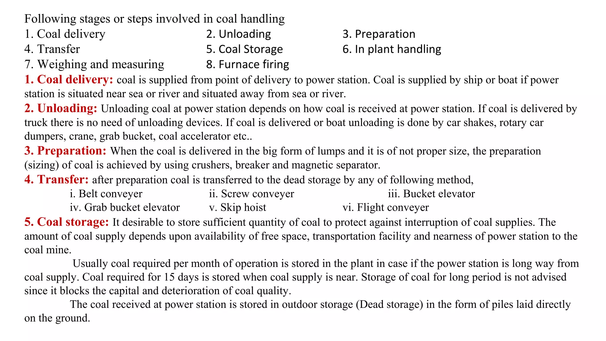
![Peat
•First stage of transformation.
•Contains less than 40 to 55 per cent carbon == more impurities.
•Contains sufficient volatile matter and lot of moisture [more smoke and more pollution].
•Left to itself, it burns like wood, gives less heat, emits more smoke and leaves a lot of ash.](https://image.slidesharecdn.com/ppeunit-1-171218101414/75/power-plant-engineering-Unit-1-15-2048.jpg)
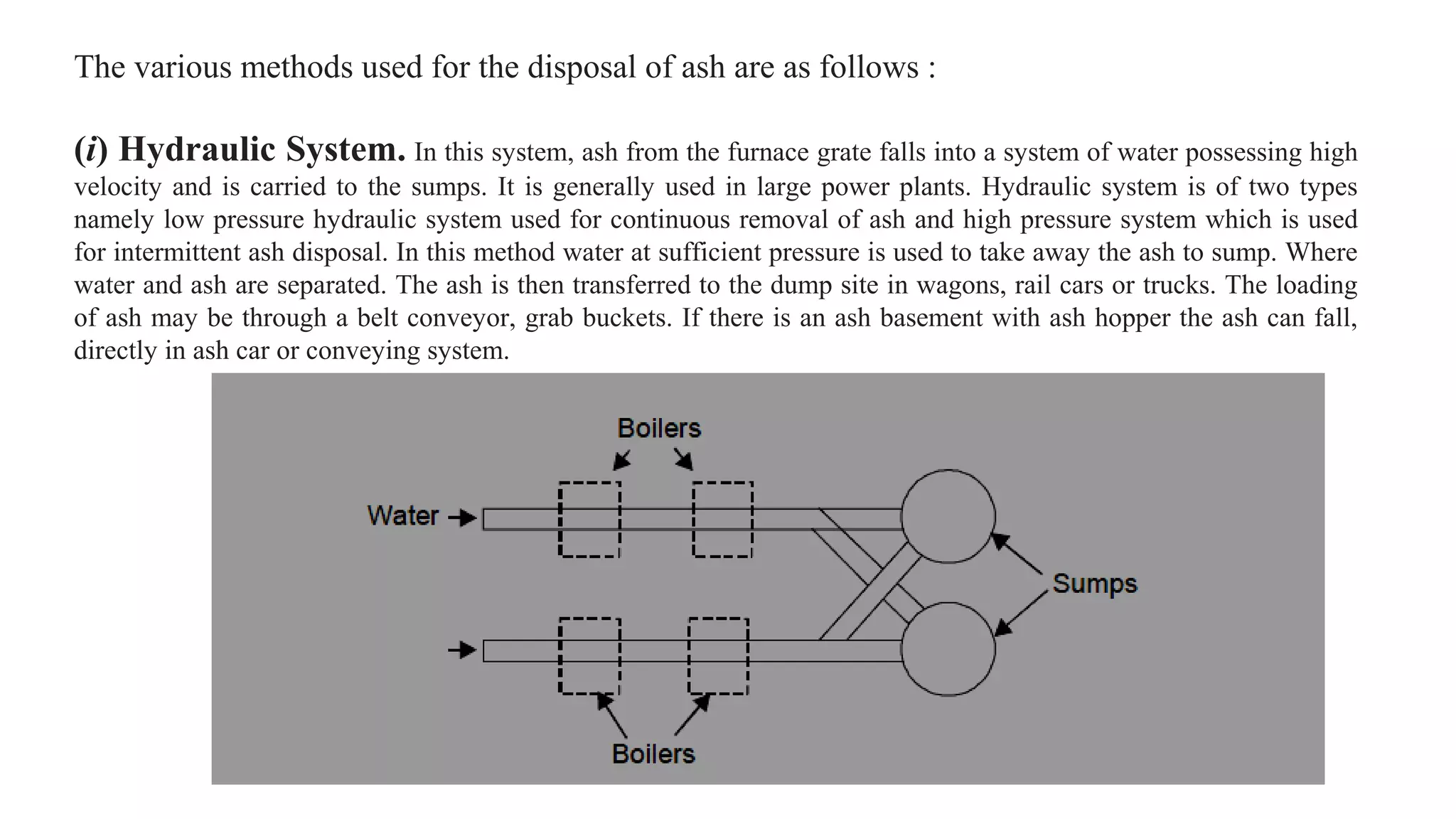
![Lignite
•Brown coal.
•Lower grade coal.
•40 to 55 per cent carbon.
•Intermediate stage.
•Dark to black brown.
•Moisture content is high (over 35 per cent).
•It undergoes SPONTANEOUS COMBUSTION [Bad. Creates fire accidents in mines]](https://image.slidesharecdn.com/ppeunit-1-171218101414/75/power-plant-engineering-Unit-1-16-2048.jpg)

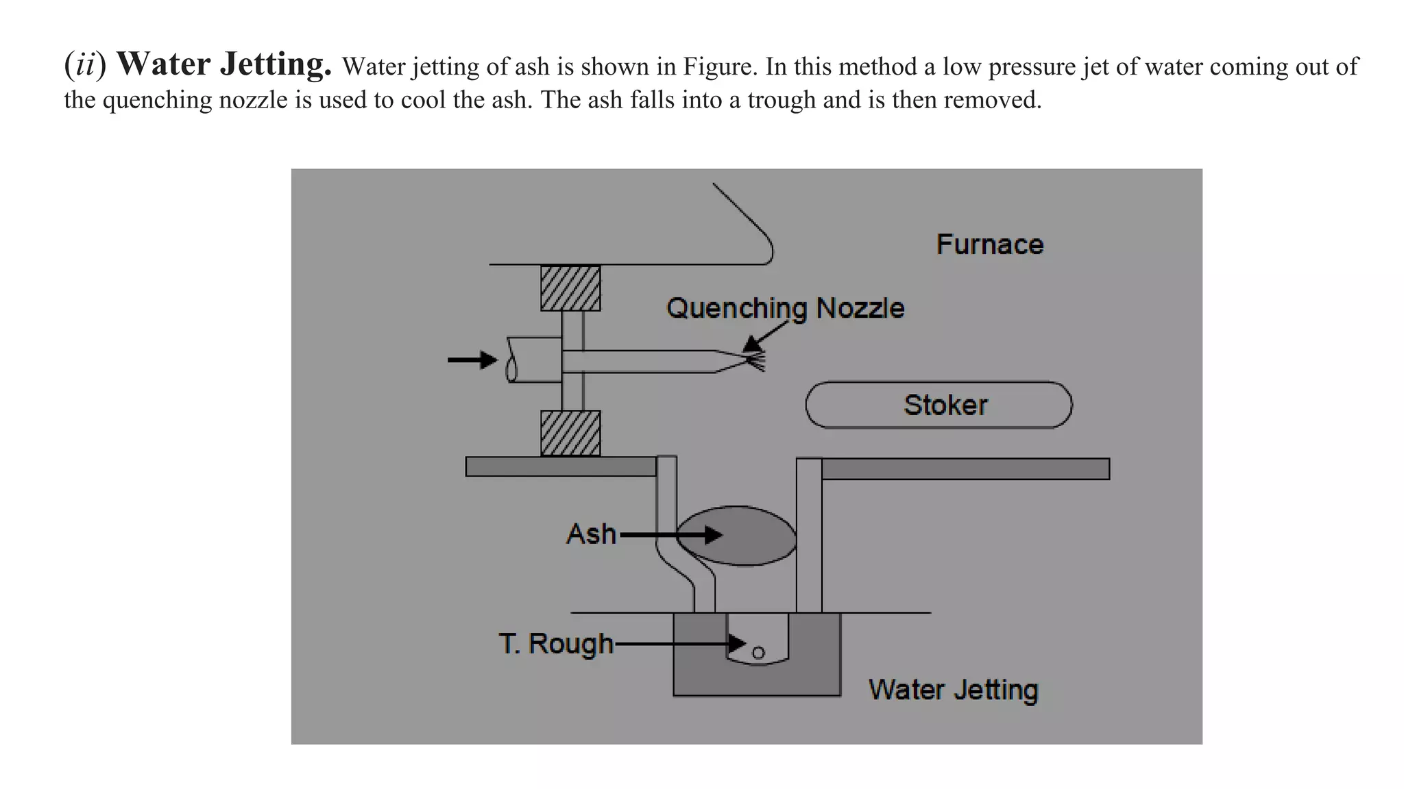
![Anthracite Coal
•Best quality; hard coal.
•80 to 95 per cent carbon.
•Very little volatile matter.
•Negligibly small proportion of moisture.
•Semi-metallic lustre.
•Ignites slowly == less loss of heat == highly efficient.
•Ignites slowly and burns with a nice short blue flame. [Complete combustion == Flame is BLUE ==
little or no pollutants. Example: LPG]
•In India, it is found only in Jammu and Kashmir and that too in small quantity.](https://image.slidesharecdn.com/ppeunit-1-171218101414/75/power-plant-engineering-Unit-1-18-2048.jpg)
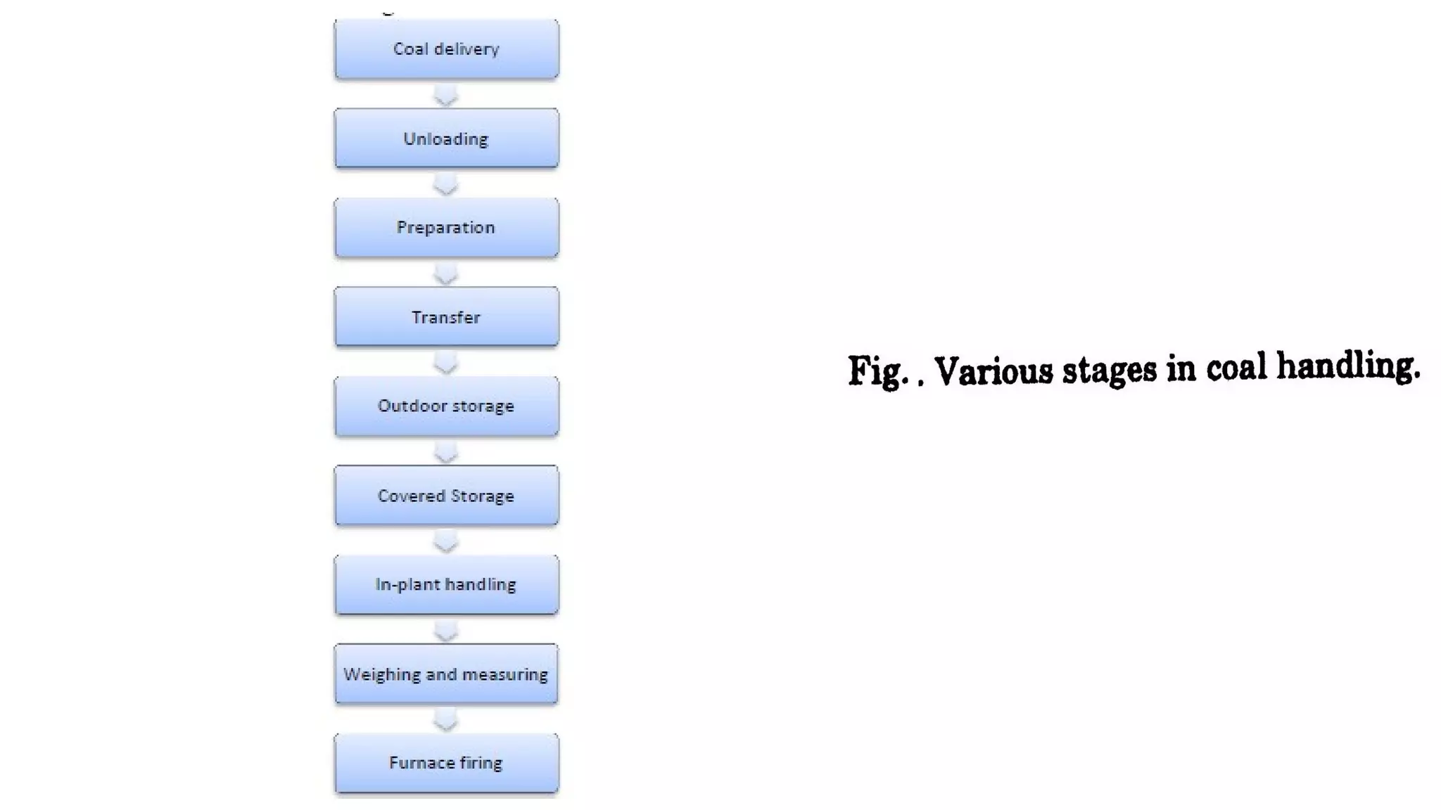
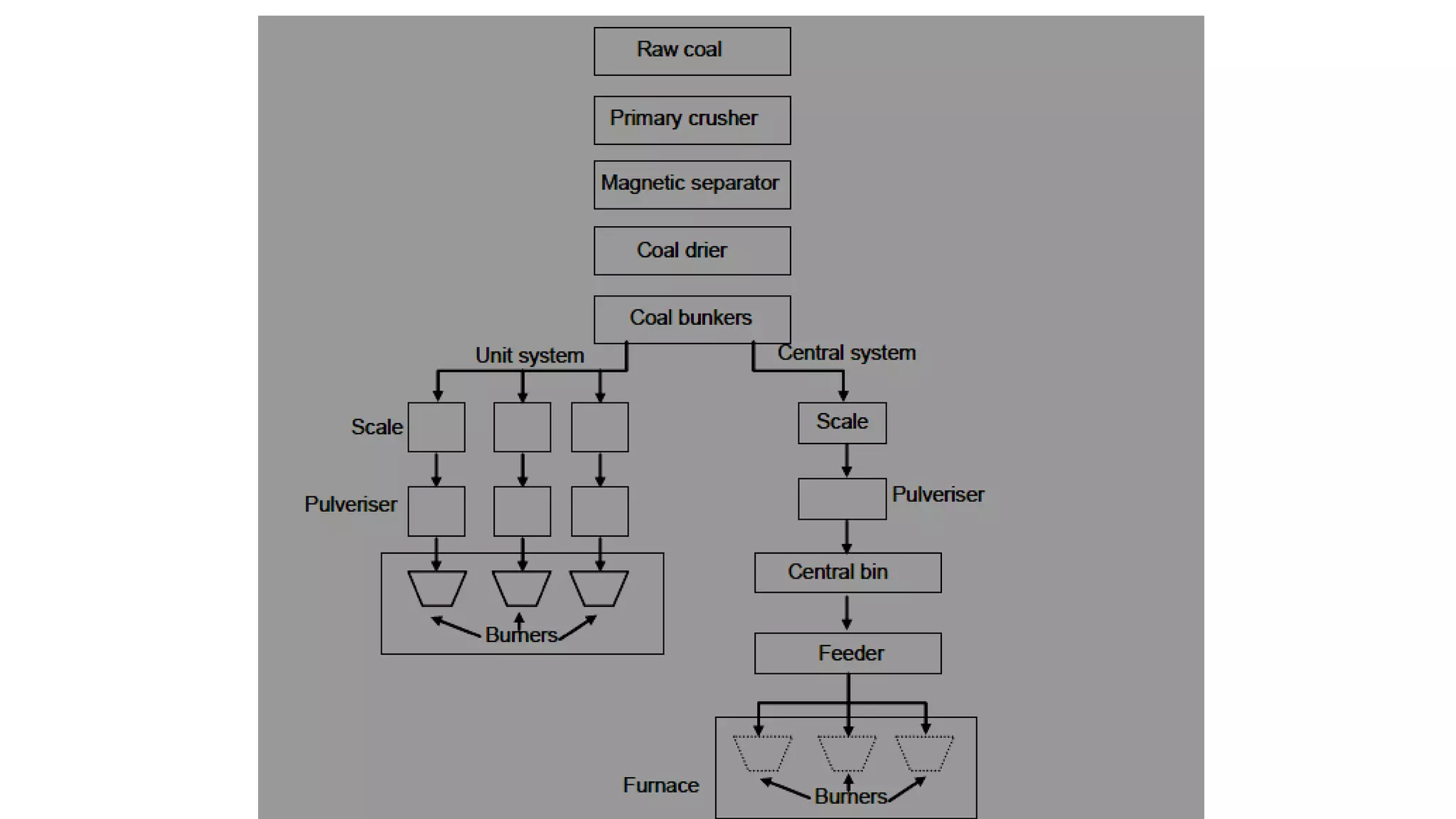


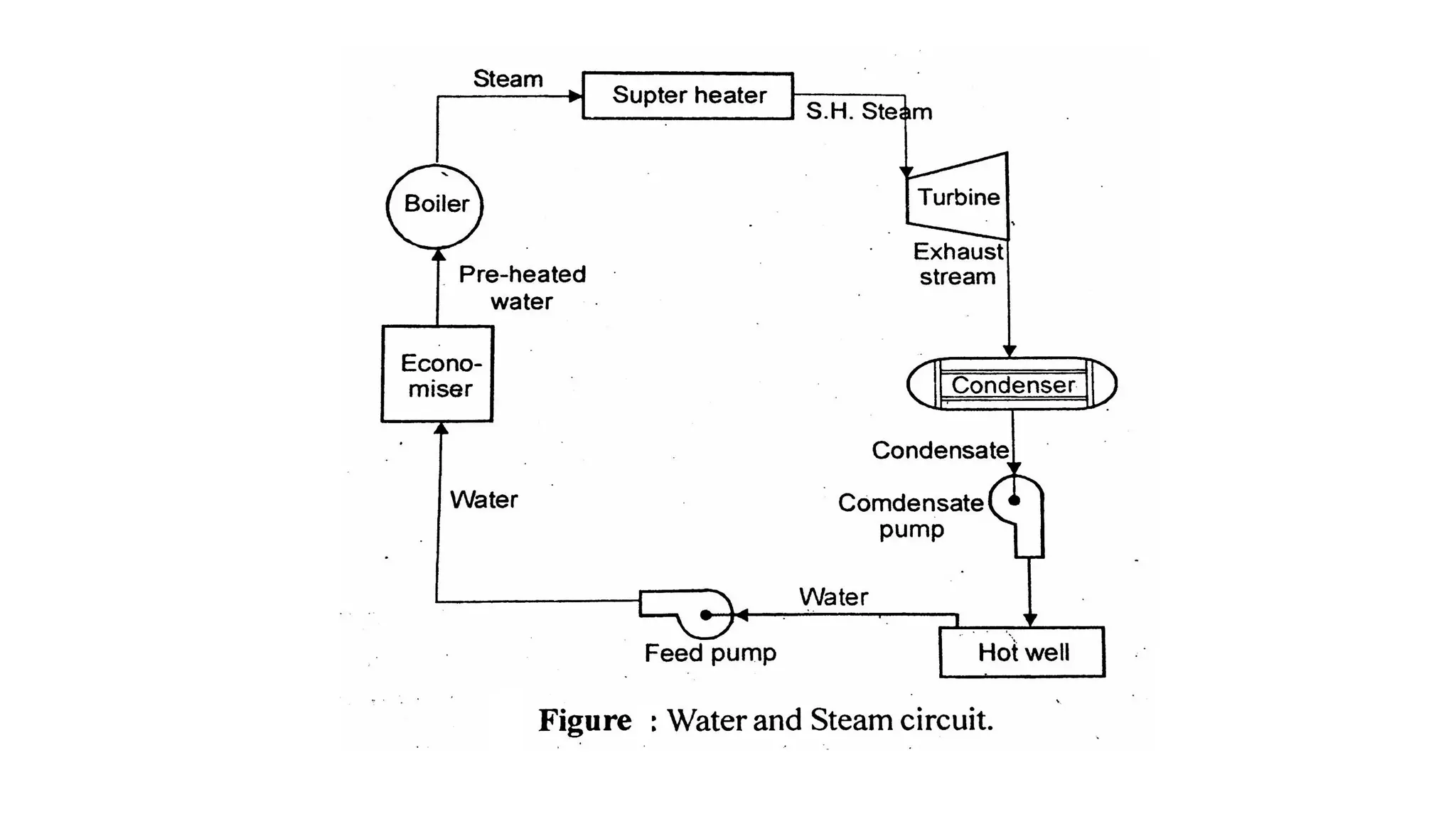
The document provides an overview of energy sources and power plants, emphasizing the current energy crisis and the need for non-polluting energy systems. It classifies various types of power plants and discusses the components and operations of steam power plants, alongside coal handling and ash disposal processes. Additionally, it outlines the importance of sustainable energy management and the efficient use of coal as a primary fuel in energy production.


![[PPT] on Steam Turbine](https://cdn.slidesharecdn.com/ss_thumbnails/spsharmafinalppt-140608082156-phpapp01-thumbnail.jpg?width=640&height=640&fit=bounds)


