The document provides a comprehensive overview of the GE Jenbacher JGS620 gas engine, detailing its specifications, working principles, and technical data for power generation using natural and various alternative gases. It describes the engine's components, efficiencies, and performance metrics, highlighting the manufacturer's expertise in gas engine technology, coupled with stringent emission standards adherence. Additionally, it includes key information on the generator's dimensions, weights, outputs, and thermal and combustion data.

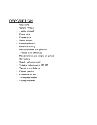
![Cylinder.
6. Ignition coil:
Ignition coil use to converts 24v to 18kv which we take from batteries.
7. Exhaust valve:
Exhaust valve use to exhaust the gas which created during engine working.
8. Piston:
A piston is a component of reciprocating engines, reciprocating pumps, gas compressors
And pneumatic cylinders, among other similar mechanisms. It is the moving component
That is contained by a cylinder and is made gas-tight by piston rings.
9. cylinder
There are 20 cylinders in this gas engine. In this there is spark plugs use to sparkblast for
Ignition.
10. Connecting Rod.
A connecting rod is an engine component that transfers motion from the piston to the
Crankshaft and functions as a lever arm.
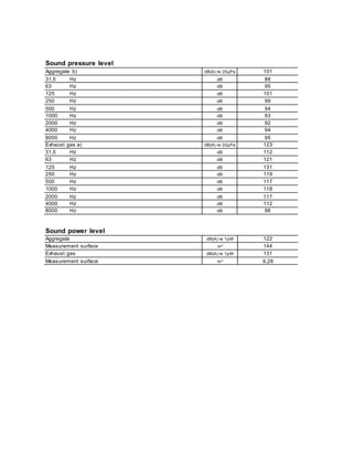
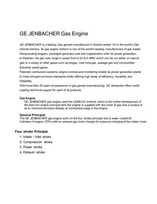
Technical Data (atGenset)
Data:
Fuel gas LHV kWh/Nm³ 9,5
100%
Energy input kW [2] 6.433
Gas volume Nm³/h *) 677
Mechanical output kW [1] 2.807
Electrical output kW el. [4] 2.739
Heat to be dissipated [5]
~ Intercooler 1st stage (Engine jacket water cooling circuit) kW 413
~ Intercooler 2nd stage (Low temperature circuit) kW 162
~ Lube oil (Engine jacket water cooling circuit) kW 315
~ Jacket water kW 515
~ Surface heat ca. kW [7] 239
~ Balance heat kW 64
Spec. fuel consumption of engine kWh/kWh [2] 2,29
Lube oil consumption ca. kg/h [3] 0,84
Electrical efficiency % 42,6%](https://image.slidesharecdn.com/gejbjgs620technicalspecifications-191226160823/85/GE-Jebachers-Gas-Engine-JGS620-technical-specifications-5-320.jpg)
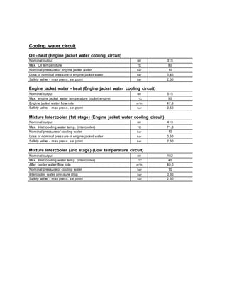
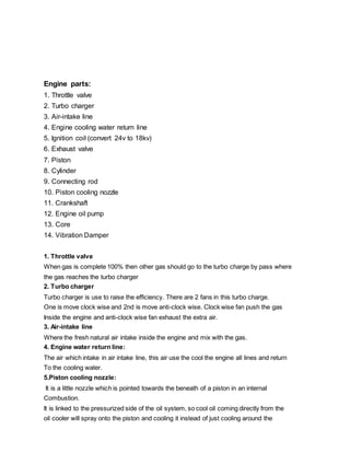
![Technical data ofengine JGS 620
Manufacturer GE Jenbacher
Engine type J 620 GS-E01
Working principle 4-Stroke
Configuration V 60°
No. of cylinders 20
Bore mm 190
Stroke mm 220
Piston displacement lit 124,75
Nominal speed rpm 1.500
Mean piston speed m/s 11,00
Length mm 5.542
Width mm 1.900
Height mm 2.540
Weight dry kg 12.000
Weight filled kg 13.000
Moment of inertia kgm² 69,21
Direction of rotation (from flywheel view) left
Flywheel connection SAE 24''
Radio interference level to VDE 0875 N
Starter motor output kW 20
Starter motor voltage V 24
Thermal energy balance
Energy input kW 6.433
Intercooler kW 575
Lube oil kW 315
Jacket water kW 515
Exhaust gas total kW 1.990
Exhaust gas cooled to 180 °C kW 1.268
Exhaust gas cooled to 100 °C kW 1.643
Surface heat kW 171
Balance heat kW 64
Exhaust gas data
Exhaust gas temperature at full load °C [8] 440
Exhaust gas mass flow rate, wet kg/h 15.635
Exhaust gas mass flow rate, dry kg/h 14.596
Exhaust gas volume, wet Nm³/h 12.335
Exhaust gas volume, dry Nm³/h 11.087
Max.admissible exhaust back pressure after engine mbar 60
Combustion air data
Combustion air mass flow rate kg/h 15.172
Combustion air volume Nm³/h 11.737
Max. admissible pressure drop in front of intake-air filter mbar 10](https://image.slidesharecdn.com/gejbjgs620technicalspecifications-191226160823/85/GE-Jebachers-Gas-Engine-JGS620-technical-specifications-7-320.jpg)