Downloaded 137 times

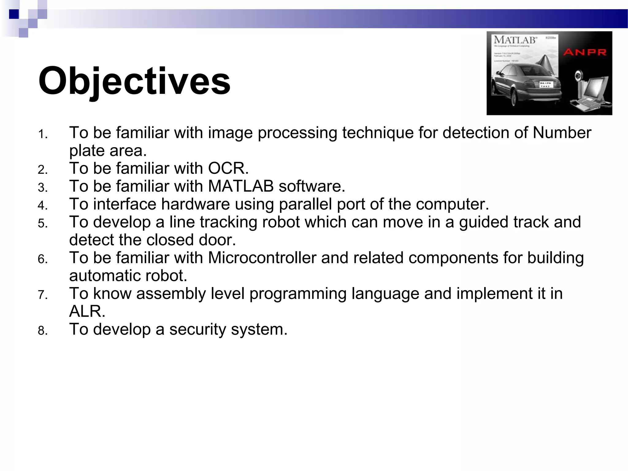
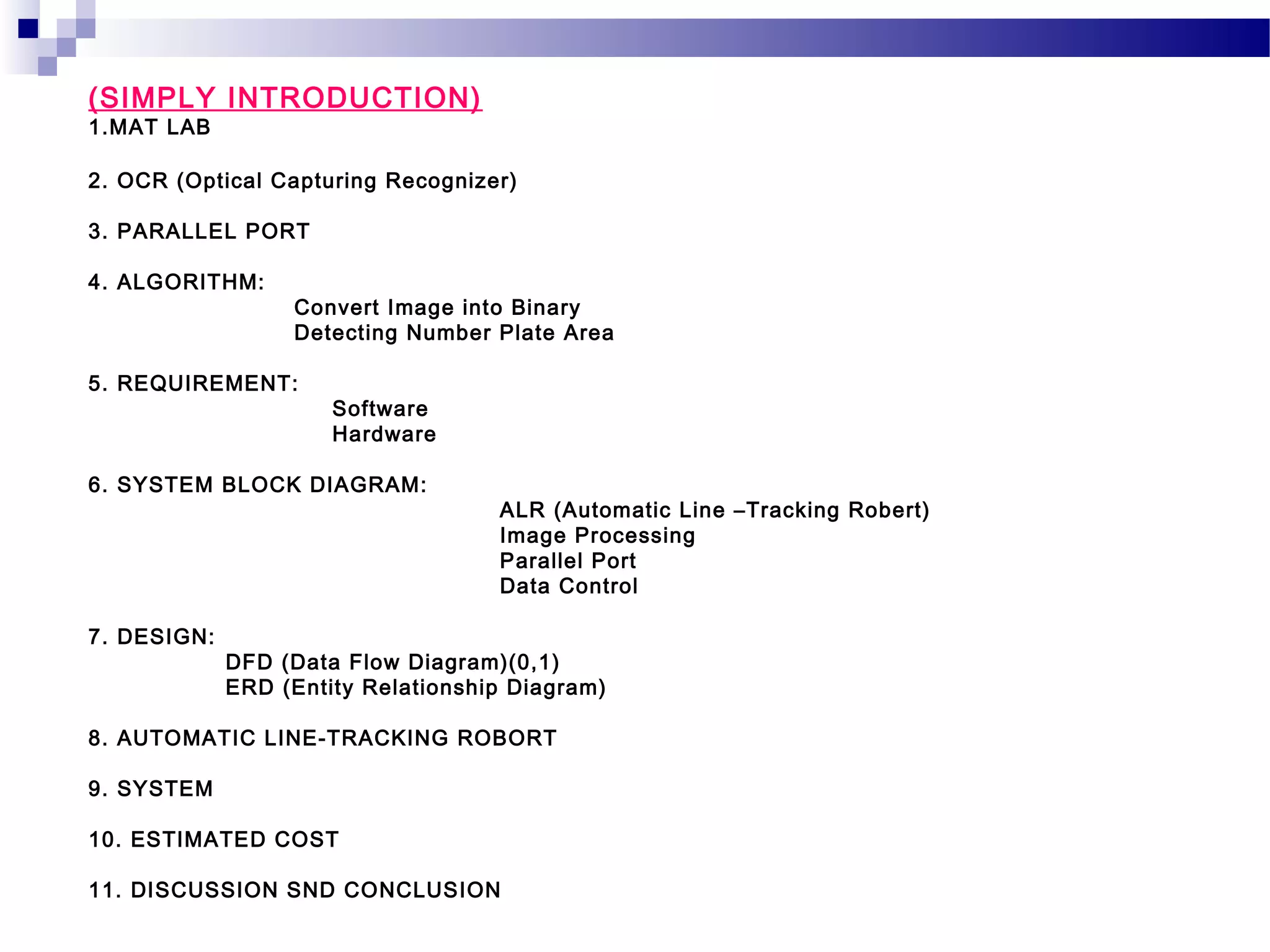
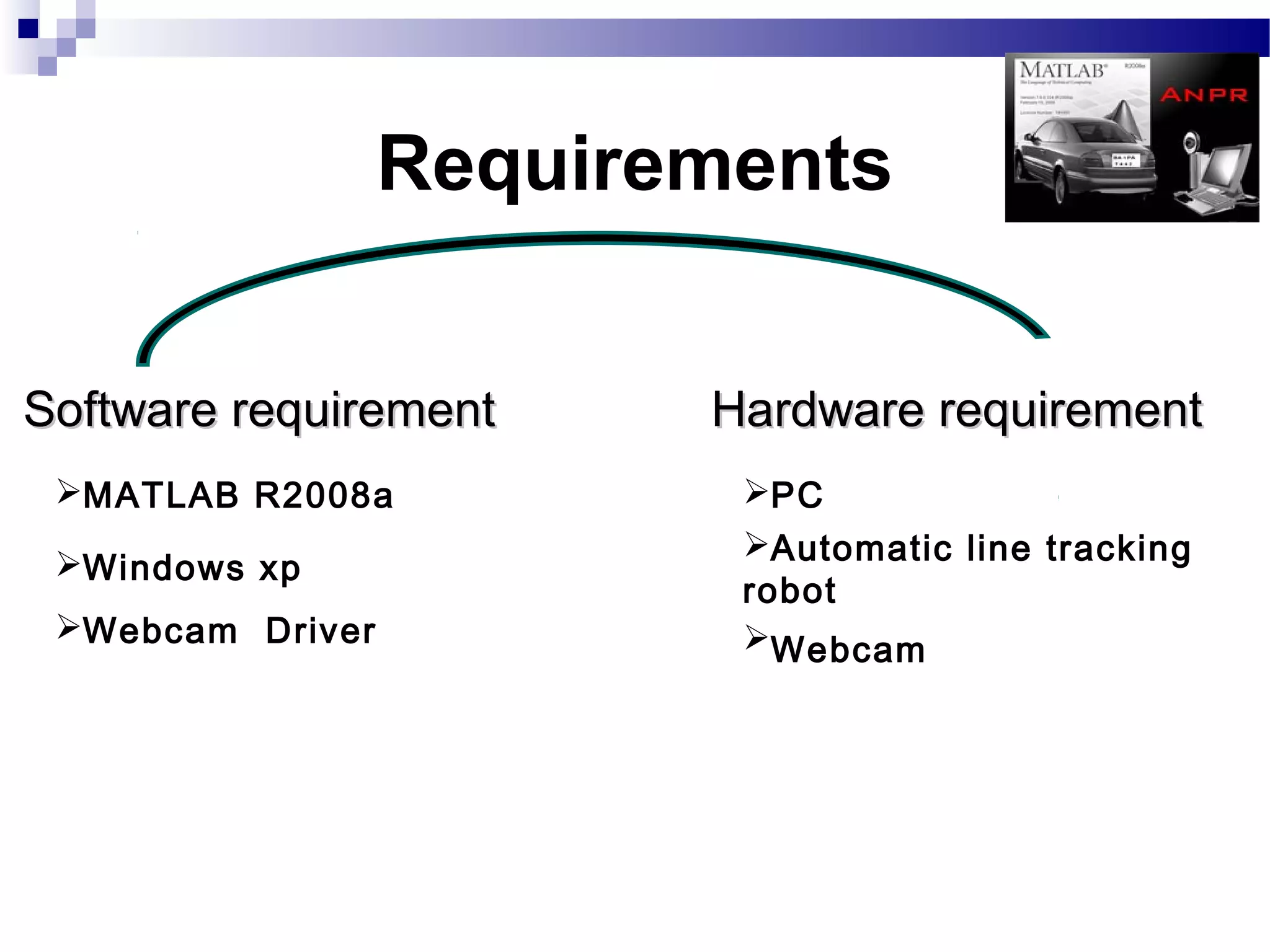


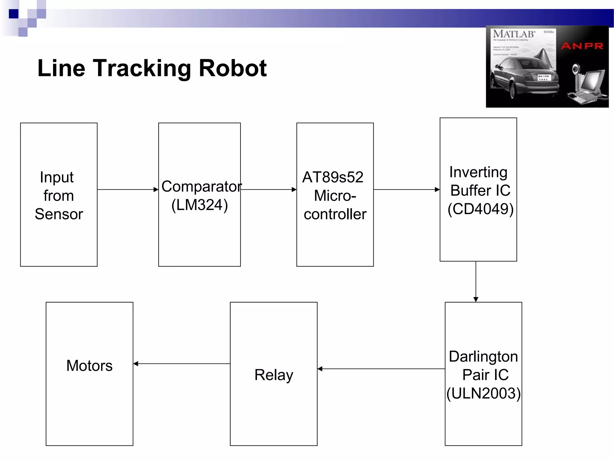

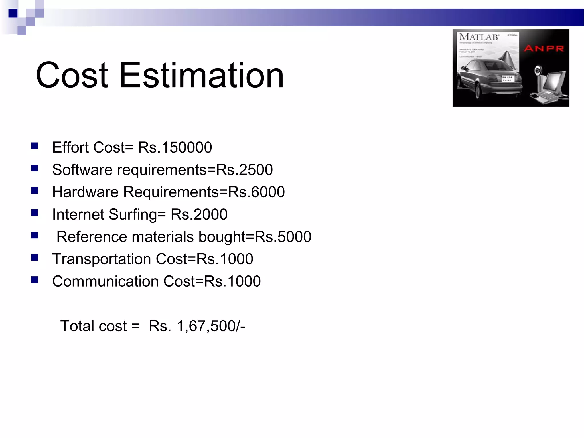


The document outlines a project aimed at developing an automatic number plate recognition system and an automatic line tracking robot (ALR) using image processing techniques, MATLAB, and hardware interfacing. It discusses the objectives, requirements, algorithms, and limitations of the system, detailing the processes involved in capturing and processing vehicle number plates for various applications, including security and traffic control. Additionally, it provides cost estimations for the project and concludes with acknowledgments to the project supervisor and supporting faculty.