Download as PDF, PPTX

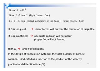
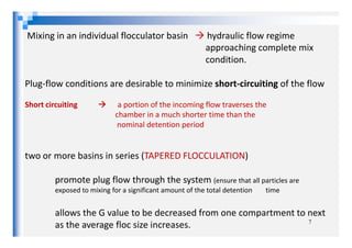
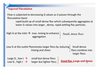
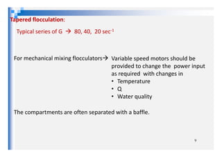
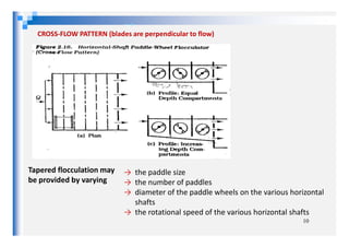
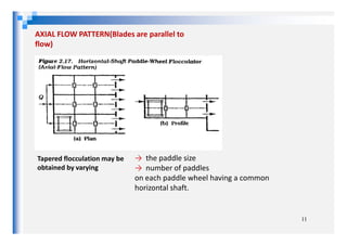
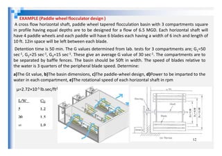
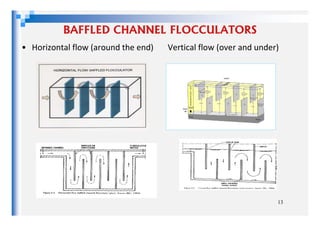


This document provides information on the design of rapid mixing (coagulation) and slow mixing (flocculation) units in water treatment. It discusses the objectives and design criteria for rapid mixing units, which is to provide complete mixing of coagulant and raw water over 20-60 seconds at 700-1000 sec-1. Slow mixing units called flocculators are used to promote particle aggregation over longer detention times of 15-30 minutes at lower velocity gradients of 10-100 sec-1. Tapered flocculation is described as a method to vary velocity gradients from higher to lower values through a basin to form dense, rapidly settling flocs. Examples are provided for designing paddle wheel and baffled channel flocculators


![Geotechnical Engineering-I [Lec #27: Flow Nets]](https://cdn.slidesharecdn.com/ss_thumbnails/27-180924141458-thumbnail.jpg?width=640&height=640&fit=bounds)


![Lecture 9 -_centralized_water_treatment_(treatment_and_disinfection)[1]](https://cdn.slidesharecdn.com/ss_thumbnails/lecture9-centralizedwatertreatmenttreatmentanddisinfection1-150122150953-conversion-gate02-thumbnail.jpg?width=640&height=640&fit=bounds)


